EP0961097A2 - Mittels einem Druckknopf kontrollierter, verlängerbarer Polizeischlagstab, der mit Kugellagern verriegelt wird - Google Patents
Mittels einem Druckknopf kontrollierter, verlängerbarer Polizeischlagstab, der mit Kugellagern verriegelt wird Download PDFInfo
- Publication number
- EP0961097A2 EP0961097A2 EP99304135A EP99304135A EP0961097A2 EP 0961097 A2 EP0961097 A2 EP 0961097A2 EP 99304135 A EP99304135 A EP 99304135A EP 99304135 A EP99304135 A EP 99304135A EP 0961097 A2 EP0961097 A2 EP 0961097A2
- Authority
- EP
- European Patent Office
- Prior art keywords
- baton
- tubular
- section
- locking
- ball bearings
- Prior art date
- Legal status (The legal status is an assumption and is not a legal conclusion. Google has not performed a legal analysis and makes no representation as to the accuracy of the status listed.)
- Withdrawn
Links
- 230000007246 mechanism Effects 0.000 title abstract description 11
- 229910000831 Steel Inorganic materials 0.000 claims description 6
- 239000010959 steel Substances 0.000 claims description 6
- 229910052782 aluminium Inorganic materials 0.000 claims description 3
- XAGFODPZIPBFFR-UHFFFAOYSA-N aluminium Chemical compound [Al] XAGFODPZIPBFFR-UHFFFAOYSA-N 0.000 claims description 3
- 239000006223 plastic coating Substances 0.000 claims 2
- 230000000994 depressogenic effect Effects 0.000 description 3
- 229910052751 metal Inorganic materials 0.000 description 3
- 239000002184 metal Substances 0.000 description 3
- 230000000694 effects Effects 0.000 description 2
- 239000000463 material Substances 0.000 description 2
- 229910000851 Alloy steel Inorganic materials 0.000 description 1
- 229920001944 Plastisol Polymers 0.000 description 1
- 208000027418 Wounds and injury Diseases 0.000 description 1
- 238000007792 addition Methods 0.000 description 1
- 229910001563 bainite Inorganic materials 0.000 description 1
- 230000006835 compression Effects 0.000 description 1
- 238000007906 compression Methods 0.000 description 1
- 238000002788 crimping Methods 0.000 description 1
- 230000006378 damage Effects 0.000 description 1
- 208000014674 injury Diseases 0.000 description 1
- 229910000734 martensite Inorganic materials 0.000 description 1
- 238000000034 method Methods 0.000 description 1
- 239000004999 plastisol Substances 0.000 description 1
- 230000000717 retained effect Effects 0.000 description 1
- 238000005096 rolling process Methods 0.000 description 1
- 238000003466 welding Methods 0.000 description 1
- 210000000707 wrist Anatomy 0.000 description 1
Images


Classifications
-
- F—MECHANICAL ENGINEERING; LIGHTING; HEATING; WEAPONS; BLASTING
- F41—WEAPONS
- F41B—WEAPONS FOR PROJECTING MISSILES WITHOUT USE OF EXPLOSIVE OR COMBUSTIBLE PROPELLANT CHARGE; WEAPONS NOT OTHERWISE PROVIDED FOR
- F41B15/00—Weapons not otherwise provided for, e.g. nunchakus, throwing knives
- F41B15/02—Batons; Truncheons; Sticks; Shillelaghs
- F41B15/022—Batons; Truncheons; Sticks; Shillelaghs of telescopic type
- F41B15/027—Batons; Truncheons; Sticks; Shillelaghs of telescopic type the telescoping sections being locked by an additional mechanical locking element
-
- Y—GENERAL TAGGING OF NEW TECHNOLOGICAL DEVELOPMENTS; GENERAL TAGGING OF CROSS-SECTIONAL TECHNOLOGIES SPANNING OVER SEVERAL SECTIONS OF THE IPC; TECHNICAL SUBJECTS COVERED BY FORMER USPC CROSS-REFERENCE ART COLLECTIONS [XRACs] AND DIGESTS
- Y10—TECHNICAL SUBJECTS COVERED BY FORMER USPC
- Y10T—TECHNICAL SUBJECTS COVERED BY FORMER US CLASSIFICATION
- Y10T403/00—Joints and connections
- Y10T403/70—Interfitted members
- Y10T403/7047—Radially interposed shim or bushing
- Y10T403/7051—Wedging or camming
- Y10T403/7052—Engaged by axial movement
Definitions
- This invention relates to a new and improved multi-stage positive lock tubular expandable police baton.
- police batons are used by police for crowd control and other police duties in place of the conventional wooden billy clubs.
- Expandable police batons are shown for example in U.S. Patents 5,320,348 and 5,160,140.
- the present invention provides a new and improved positive lock quick release police baton.
- the collapse of the extended sections into the larger tubular section is accomplished by the use of a single axially positioned push button mechanism which releases ball bearing locking mechanisms in the sections.
- This invention discloses a positive lock button release police baton, preferably having three sections. Each section successively gets smaller in diameter with the smaller sections telescoping into and out of larger section in which they are slidably positioned.
- the middle section and the smaller inner section are moved outwardly until they are locked in place by locking means when each of the sections are fully extended.
- a push button is depressed to cause an axially positioned release rod to disengage a first ball bearing locking means holding the middle section to permit it to telescope into the larger end section.
- a second ball bearing locking means holding the smaller section in place relative to said middle section is caused to disengage by the tip of the release rod so that the smaller end section may telescope into said middle section.
- the baton may be made out of any metal such as steel, aluminum or any combination thereof.
- the preferred steel is an alloy steel such as 4130.
- the steel may be hardened if desired, for example to 38 to 44 as measured on the Rockwell C Scale, using conventional heat treating process which produce martensite or bainite steel.
- the preferred aluminum is 6061 or 7075.
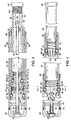
- Fig. 1 shows the baton in a collapsed condition
- Fig. 2 shows the baton in a fully extended (telescoping) condition
- the baton 20 has a first (outer) tubular handle section 22, a second (middle) tubular section 24 and a third (inner) tubular section 26.
- a rear cap is provided at 28, which is preferably threaded to handle section 22.
- a tip is provided at 30 which has a threaded shaft 30a (Fig. 3) for screwing into threads of the third tubular section 26.
- the tip 30 may be coated in an elastic or plastic material, such as rubber, Plastisol, or other similar materials well known in the art, in order to protect against unintended injury.
- a button 32 is provided at the base of the cap which is depressed by the user to permit the baton to collapse from the extended position as shown in Fig. 2 to the collapsed condition shown in Fig. 1.
- Fig. 3 illustrates the first, second and third tubular sections in the collapsed position as shown in Fig. 1.
- the releasing rod 34 has a camming surface 36 and a notch 38.
- the notch 38 permits the camming surface to resiliently collapse radially.
- the release rod 34 is fixedly coupled to the button 32 for movement therewith and a spring 40 and a platform 42 fixedly supported by the rear cap 28 (e.g., by welding, threading, press fit or bonding etc.) causes the spring to be in compression to force the button 32 to project outwardly from the rear cap 28.
- An O-ring 44 is provided between the threaded rear cap 28 and the first tubular section 22 as shown.
- the first locking cam is shaped with a large diameter portion 47, a reduced diameter portion 48, and a camming surface 49.
- the locking cam is provided with a center bore with a camming surface 56.
- the locking cam 46 bears against ball bearings 50 that are supported in a retainer holes 50".
- a spring 60 is used to urge the locking cam 46 toward the button end 32 of the baton.
- the middle tubular section 24 is fitted with a collar 62 that may be press fit, threaded, welded, bonding, peaned or swaged onto the end of the tubular middle section 24.
- a washer 61 may optionally be provided on a shoulder formed on the inside surface of the tubular middle section 24 to support the spring 60.
- the locking cam member 46 is further provided with a shoulder or flange 63 for retaining the cam against the ball bearings 50 when the locking cam 46 is fully extended.
- a second locking cam member 64 Slidably disposed inside the third inner section 26 is a second locking cam member 64, which closely resemble the first locking cam member 46, except that it is smaller.
- the second locking cam is shaped with a large diameter portion 65, a reduced diameter portion 66, and a camming surface 67.
- the locking cam is provided with a center bore -with a camming surface 58.
- the locking cam 64 bears against ball bearings 68, which are supported in retaining holes 68".
- a spring 70 is used to urge the locking cam 64 toward the button end 32 of the baton.
- the inner tubular section 26 is fitted with a collar 72 that may be press fit, threaded, welded, bonding, peaned or swaged onto the end of the tubular inner section 26.
- a washer 71 may optionally be provided on a shoulder formed on the inside surface of the tubular middle section 26 to support the spring 70.
- the locking cam member 64 is further provided with a shoulder or flange 74 for retaining the cam against the ball bearings 50 when the locking cam 64 is fully extended.
- the threaded portion 30a of the tip 30 is adjacent to an insert 76 provided with a receiving space for the camming portion 36 of the release rod 34.
- a reduced diameter portion 76a of the insert 76 engages the rod 34 adjacent to the camming portion 36 maintains the baton in a collapsed configuration.
- a quick throw out (or wrist "flick") of the baton overcomes the hold back effect of this resistance, and also will allow the rod tip 36 to pass through the first and second locking cams 46, 64. If desired, a slow passive draw of the baton elements may also be employed.
- the notch 38 permits radial resilient collapsing of the camming portion 36 when passing through the locking cams and the threaded portion 30a.
- Fig. 4 there is shown the baton in the fully telescoped (extended) position.
- the locking mechanism ball bearings 50 and 68 are shown positioned in place to positively lock the baton for use.
- the ball bearings 50 and 68 snap in place into grooves 50', 68' formed in the interiors of tubular members 22 and 24, respectively.
- the locking cam members 46, 64 are biased toward the button end 32 of the baton, such that the large diameter portions 47, 65 of the locking cam members 46, 64 maintain the ball bearings 50, 68 in their respective grooves 50', 68'.
- the third tubular section 26 moves against a metal bushing 78 e.g., of metal e.g., 4130 or 1020 steel which can be either threaded in as with bushing 80 or force fit and then having the end of the tubular member 24 peaned over to hold it in place as shown.
- This bushing may be threaded, bonded or welded.
- the bushings can also have a slip fit outside diameter retained by rolling, swaging or crimping of the edge of the tubular members.
- Fig. 5 illustrates the collapsing of the baton and in particular, the button 32 being depressed in the direction of arrow A, which causes the camming surface 36 of the release rod 34 to engage the chamfered cam surface 56 of locking cam member 46 to force the cam member 46 forward in the direction of arrow B. This in turn moves the locking cam member 46 such that the reduced diameter portion 48 underlies the ball bearings 50, allowing them to disengage from the groove 50' formed in tubular member 22. In this way, the baton section 24 can collapse into the section 22 by being pushed by the user to the left as depicted in Fig. 5.
- Fig. 6 illustrates the camming surface 36 engaging chamfered camming surface 58 of the second locking cam member 64, which results in the cam member 64 moving in the direction of arrow C. This in turn moves the locking cam member 64 such that the reduced diameter portion 66 underlies the ball bearings 68, allowing them to disengage from the groove 68' formed in tubular member 24. After the disengagement of ball bearings 68, the third tubular section 26 can collapse into the middle tubular section 24 in the direction of arrow D, resulting in the collapsed configuration shown in Fig. 3.
- Fig. 7 is a cross-sectional view of the first locking arrangement for maintaining the second tubular section 24 in an extended configuration vis-à-vis the first handle section 22, as shown in Fig. 4.
- the large diameter portion 47 of the locking cam member 46 abuts the ball bearings 50, the locking cam member 46 being biased by a spring 60 in the locking position as shown in the figure.
- a central bore 54 of the locking cam member 46 is also shown.
- the ball bearings 50 are urged against the interior surface of the tubular handle section 22, and into locking groove 50' formed on the interior wall of tubular section 22.
- the camming portion 36 of the release rod 34 resides outside the locking cam member 46, as seen in Fig. 4.
- Fig. 8 is a cross-sectional view of the first locking arrangement in a released state, as depicted in Fig. 5.
- the locking cam member 46 is shown positioned such that the reduced diameter portion 48 is underlying the ball bearings 50, under the influence of the camming portion 38 of the release rod 34 passing into the bore 54.
- the locking cam member 46 comprises a camming surface 56 to aid in the passing of the camming surface 36 of the release rod 34 into the bore 54.
- the ball bearings 50 are shown disengaged from the groove 50', allowing the sections of the baton to be collapsed. As the sections are moved into a collapsed configuration, the camming portion 36 of the release rod 34 radially collapses resiliently because of the notch 38, allowing the camming portion 36 of the release rod 34 to penetrate the first locking cam 46.
- the depiction of the first locking mechanism of Figs. 7 and 8 applies to the operation of the second locking mechanism.
- the initial release that is the release of the first section 22 vis-à-vis the middle section, requires the operation of the button 32 to advance the release rod 34.
- the present invention provides a new and improved positive lock mechanism which uses an axial cam push baton positive lock mechanism which makes for easy use by the police officer by merely pushing a single button to effect the collapse of the three section baton. It is also clear from the above that the mechanism herein is also applicable to two section batons.
Landscapes
- Engineering & Computer Science (AREA)
- General Engineering & Computer Science (AREA)
- Mutual Connection Of Rods And Tubes (AREA)
- Refuge Islands, Traffic Blockers, Or Guard Fence (AREA)
Applications Claiming Priority (2)
| Application Number | Priority Date | Filing Date | Title |
|---|---|---|---|
| US85699 | 1998-05-27 | ||
| US09/085,699 US6238292B1 (en) | 1998-05-27 | 1998-05-27 | Push button controlled police baton with ball bearing locking mechanism |
Publications (2)
| Publication Number | Publication Date |
|---|---|
| EP0961097A2 true EP0961097A2 (de) | 1999-12-01 |
| EP0961097A3 EP0961097A3 (de) | 1999-12-22 |
Family
ID=22193377
Family Applications (1)
| Application Number | Title | Priority Date | Filing Date |
|---|---|---|---|
| EP99304135A Withdrawn EP0961097A3 (de) | 1998-05-27 | 1999-05-27 | Mittels einem Druckknopf kontrollierter, verlängerbarer Polizeischlagstab, der mit Kugellagern verriegelt wird |
Country Status (2)
| Country | Link |
|---|---|
| US (1) | US6238292B1 (de) |
| EP (1) | EP0961097A3 (de) |
Cited By (6)
| Publication number | Priority date | Publication date | Assignee | Title |
|---|---|---|---|---|
| FR2821927A1 (fr) * | 2001-03-08 | 2002-09-13 | Gk Productions | Baton de defense et d'attaque |
| WO2004097328A1 (de) | 2003-04-29 | 2004-11-11 | Bopp, Wolfgang | Schlagstock |
| EP2604966A3 (de) * | 2011-12-13 | 2014-12-31 | Starkey Industries, LLC | Mehrstufiger Schlagstock mit Drucktaster-Freigabe |
| CN107560497A (zh) * | 2017-06-02 | 2018-01-09 | 广东纳丽德移动照明有限责任公司 | 伸缩警棍 |
| US10533908B1 (en) | 2018-01-31 | 2020-01-14 | Honeywell Federal Manufacturing & Technologies, Llc | Activation component testing apparatus |
| US11067359B1 (en) * | 2021-01-21 | 2021-07-20 | Kuei-Chih Chiang | Expandable baton |
Families Citing this family (36)
| Publication number | Priority date | Publication date | Assignee | Title |
|---|---|---|---|---|
| US6481142B1 (en) * | 2000-11-03 | 2002-11-19 | Mccarthy Patrick M. | Lock for a gun stock recoil reduction device |
| GB0506363D0 (en) | 2005-03-30 | 2005-05-04 | Wyko Equip | Tyre building drum |
| KR200400373Y1 (ko) * | 2005-08-17 | 2005-11-03 | 정재설 | 다단 절첩식 호신용 봉 |
| US20070072684A1 (en) * | 2005-09-23 | 2007-03-29 | Parsons Kevin L | Expandable baton with low profile tip |
| US7611398B2 (en) * | 2006-05-16 | 2009-11-03 | Hasbro, Inc. | Toy sword |
| US7416490B2 (en) * | 2006-11-06 | 2008-08-26 | Armanent Systems And Procedures, Inc. | Expandable/baton with twist release for retraction |
| US8127454B1 (en) * | 2008-04-28 | 2012-03-06 | Bradshaw Medical, Inc. | Rod cutter |
| JP2010002149A (ja) * | 2008-06-23 | 2010-01-07 | Hogi Kenkyusho:Kk | 伸縮棒 |
| US20110053694A1 (en) * | 2009-08-27 | 2011-03-03 | Wood Robert P | Hand-held anti-assault weapon |
| WO2012012697A1 (en) * | 2010-07-22 | 2012-01-26 | Wyko Tire Technology, Inc. | Bearing expansion lock |
| US8771085B1 (en) | 2010-08-06 | 2014-07-08 | Arthur C. Clyde | Modular law enforcement baton |
| US8601923B1 (en) | 2010-10-29 | 2013-12-10 | Bradshaw Medical, Inc. | Rod cutter with exchangeable cutters |
| US8794782B2 (en) * | 2010-11-12 | 2014-08-05 | Glenn Bushee | Baton light |
| US8640563B2 (en) * | 2011-05-25 | 2014-02-04 | Hamilton Sundstrand Corporation | Ram air turbine deployment actuator |
| US10189221B2 (en) | 2012-08-10 | 2019-01-29 | Davian Enterprises, LLC | Transfer ring shoe and transfer ring having varied shoe profile |
| WO2014110271A1 (en) | 2013-01-09 | 2014-07-17 | Safariland, Llc | Expandable baton with locking mechanism |
| TWI502163B (zh) * | 2013-03-06 | 2015-10-01 | Kantas Products Co Ltd | The telescopic control mechanism of the batons |
| US9677844B2 (en) | 2013-03-06 | 2017-06-13 | Starkey Industries, Llc | Telescoping baton with improved stopping and shock absorbing assembly |
| KR102205188B1 (ko) | 2013-06-07 | 2021-01-20 | 다비안 엔터프라이즈, 엘엘씨 | 이동 범위가 증가된 타이어 구축 드럼 |
| US9677843B2 (en) * | 2013-07-31 | 2017-06-13 | Armament Systems And Procedures, Inc. | Baton with recessed control button |
| US9719753B2 (en) * | 2013-07-31 | 2017-08-01 | Armament Systems And Procedures, Inc. | Baton with external control button |
| RU2684094C2 (ru) | 2014-02-07 | 2019-04-03 | Дейвиан Энтерпрайзиз, Ллк | Расширяемый брекерно-протекторный барабан с сегментами переменной кривизны |
| US9399522B2 (en) | 2014-02-20 | 2016-07-26 | Hamilton Sundstrand Corporation | Ram air turbine actuator |
| CN204140574U (zh) * | 2014-08-22 | 2015-02-04 | 奇立科技有限公司 | 伸缩管体及具有该伸缩管体的手杖及晒衣竿 |
| AT516948B1 (de) * | 2015-09-14 | 2016-10-15 | Damian Schönborn | Rückstoßdämpfende Vorrichtung |
| IL251324A0 (en) * | 2017-03-21 | 2017-06-29 | Moran Aviad | Weapons |
| CN108871054B (zh) * | 2018-04-24 | 2024-05-28 | 广州慈宇安防科技有限公司 | 一种带辅件的伸缩式反拉解锁警棍 |
| CN108827068B (zh) * | 2018-04-24 | 2024-05-28 | 广州慈宇安防科技有限公司 | 一种警棍用伸缩反拉内藏式解锁杆 |
| US11358356B2 (en) | 2018-09-27 | 2022-06-14 | Davian Enterprises, LLC | Transfer ring with block and rail system |
| CZ2018640A3 (cs) * | 2018-11-21 | 2020-01-08 | Břetislav Košťál | Teleskopický skládací obušek |
| WO2020160012A1 (en) | 2019-01-28 | 2020-08-06 | Davian Enterprises, LLC | Expandable belt and tread drum with reverse offset fingers |
| KR20230003534A (ko) | 2020-04-22 | 2023-01-06 | 윌리엄 에이. 존스 | 타이어 성형기용 숄더 어셈블리 |
| US12162234B2 (en) | 2020-05-29 | 2024-12-10 | Davian Enterprises, LLC | Transfer ring shoe and transfer ring with reduced air entrapment features |
| BR212022018349U2 (pt) * | 2020-09-04 | 2023-03-14 | Alberto Fernandes Carlos | Bastão retrátil flexível |
| WO2022120117A2 (en) | 2020-12-03 | 2022-06-09 | Davian Enterprises, Llc (Dba Wyko Tire Technologies) | Expandable belt and tread drum with magnetic deck fixing |
| US12345501B2 (en) * | 2021-01-21 | 2025-07-01 | Kuei-Chih Chiang | Expandable baton |
Citations (2)
| Publication number | Priority date | Publication date | Assignee | Title |
|---|---|---|---|---|
| US5160140A (en) | 1989-09-28 | 1992-11-03 | Monadnock Lifetime Products, Inc. | Expandable baton with spring biased latch means |
| US5320348A (en) | 1993-02-11 | 1994-06-14 | Monadnock Lifetime Products, Inc. | Telescopic baton with shock absorbing means |
Family Cites Families (13)
| Publication number | Priority date | Publication date | Assignee | Title |
|---|---|---|---|---|
| US3302960A (en) * | 1964-03-20 | 1967-02-07 | Adolf L Herrmann | Locking device with rolling detents |
| US3507528A (en) * | 1965-02-16 | 1970-04-21 | Westinghouse Electric Corp | Locking device |
| US3469871A (en) * | 1967-08-14 | 1969-09-30 | Norco Inc | Releasable locking device |
| US4037839A (en) | 1975-12-31 | 1977-07-26 | Nelson Norman C | Collapsible baton |
| US5348297A (en) | 1988-10-07 | 1994-09-20 | Parsons Kevin L | Expandable baton with locking joints |
| US5110375A (en) | 1990-09-20 | 1992-05-05 | Parsons Kevin L | Baton method of heat treating expandable |
| USD333693S (en) | 1990-09-28 | 1993-03-02 | Armament Systems And Procedures, Inc. | Police side handle training baton |
| USD333692S (en) | 1990-09-28 | 1993-03-02 | Armament Systems And Procedures, Inc. | Police side handle baton |
| US5161800A (en) | 1991-08-16 | 1992-11-10 | Armament Systems And Procedures, Inc. | Retainer clip for expanding baton |
| US5149092A (en) | 1991-08-16 | 1992-09-22 | Kevin Parsons | Locking means for extendable baton |
| US5356139A (en) | 1993-01-08 | 1994-10-18 | Armament Systems And Procedures, Inc. | Expandable baton with sections made of dissimilar materials |
| US5407197A (en) | 1993-09-30 | 1995-04-18 | Armament Systems And Procedures | Expandable baton with coupler |
| GB2303432A (en) | 1995-07-21 | 1997-02-19 | Monadnock Lifetime Prod | Push button controlled police baton |
-
1998
- 1998-05-27 US US09/085,699 patent/US6238292B1/en not_active Expired - Lifetime
-
1999
- 1999-05-27 EP EP99304135A patent/EP0961097A3/de not_active Withdrawn
Patent Citations (2)
| Publication number | Priority date | Publication date | Assignee | Title |
|---|---|---|---|---|
| US5160140A (en) | 1989-09-28 | 1992-11-03 | Monadnock Lifetime Products, Inc. | Expandable baton with spring biased latch means |
| US5320348A (en) | 1993-02-11 | 1994-06-14 | Monadnock Lifetime Products, Inc. | Telescopic baton with shock absorbing means |
Cited By (7)
| Publication number | Priority date | Publication date | Assignee | Title |
|---|---|---|---|---|
| FR2821927A1 (fr) * | 2001-03-08 | 2002-09-13 | Gk Productions | Baton de defense et d'attaque |
| WO2004097328A1 (de) | 2003-04-29 | 2004-11-11 | Bopp, Wolfgang | Schlagstock |
| US7488255B2 (en) | 2003-04-29 | 2009-02-10 | Wolfgang Bopp | Interlockable telescopic baton |
| EP2604966A3 (de) * | 2011-12-13 | 2014-12-31 | Starkey Industries, LLC | Mehrstufiger Schlagstock mit Drucktaster-Freigabe |
| CN107560497A (zh) * | 2017-06-02 | 2018-01-09 | 广东纳丽德移动照明有限责任公司 | 伸缩警棍 |
| US10533908B1 (en) | 2018-01-31 | 2020-01-14 | Honeywell Federal Manufacturing & Technologies, Llc | Activation component testing apparatus |
| US11067359B1 (en) * | 2021-01-21 | 2021-07-20 | Kuei-Chih Chiang | Expandable baton |
Also Published As
| Publication number | Publication date |
|---|---|
| US6238292B1 (en) | 2001-05-29 |
| EP0961097A3 (de) | 1999-12-22 |
Similar Documents
| Publication | Publication Date | Title |
|---|---|---|
| EP0961097A2 (de) | Mittels einem Druckknopf kontrollierter, verlängerbarer Polizeischlagstab, der mit Kugellagern verriegelt wird | |
| US8721459B2 (en) | Multi-stage push button release baton | |
| US6231447B1 (en) | Push button controlled police baton | |
| US5372363A (en) | Composite expandable baton with magnetic retaining means | |
| US6619078B1 (en) | Barrel lock | |
| US20060277811A1 (en) | Gun barrel cleaning device with quick-detachable cleaning implement | |
| US5685102A (en) | Snap-on firearm adapter | |
| US7488255B2 (en) | Interlockable telescopic baton | |
| US4037839A (en) | Collapsible baton | |
| US12305955B2 (en) | Extendable baton with damage resistant locking mechanism | |
| US6331091B2 (en) | Control-rod actuated axle assembly | |
| US5348297A (en) | Expandable baton with locking joints | |
| US20140194212A1 (en) | Expandable Baton With Locking Mechanism | |
| US9719753B2 (en) | Baton with external control button | |
| US20080247814A1 (en) | Release pin | |
| US5110375A (en) | Baton method of heat treating expandable | |
| US9677843B2 (en) | Baton with recessed control button | |
| US5595386A (en) | Elongated button lock for expandable batons | |
| US20020072436A1 (en) | Baseball bat with a ball-serving device | |
| CA2167844A1 (en) | Axially Swaged Fitting | |
| EP0780657A1 (de) | Verlängerbarer Schlagstab mit aus unterschiedlichen Materialien gefertigten Teilen | |
| US10030681B2 (en) | Telescopic tube assembly | |
| US6439797B1 (en) | Fastener and fastener-rod assembly | |
| US6056643A (en) | Expandable baton | |
| US5667441A (en) | Concealable expandable baton with key ring |
Legal Events
| Date | Code | Title | Description |
|---|---|---|---|
| PUAI | Public reference made under article 153(3) epc to a published international application that has entered the european phase |
Free format text: ORIGINAL CODE: 0009012 |
|
| PUAL | Search report despatched |
Free format text: ORIGINAL CODE: 0009013 |
|
| AK | Designated contracting states |
Kind code of ref document: A2 Designated state(s): CH DE DK ES FR GB IE LI NL SE |
|
| AX | Request for extension of the european patent |
Free format text: AL;LT;LV;MK;RO;SI |
|
| AK | Designated contracting states |
Kind code of ref document: A3 Designated state(s): AT BE CH CY DE DK ES FI FR GB GR IE IT LI LU MC NL PT SE |
|
| AX | Request for extension of the european patent |
Free format text: AL;LT;LV;MK;RO;SI |
|
| AKX | Designation fees paid |
Free format text: CH DE DK ES FR GB IE LI NL SE |
|
| STAA | Information on the status of an ep patent application or granted ep patent |
Free format text: STATUS: THE APPLICATION IS DEEMED TO BE WITHDRAWN |
|
| 18D | Application deemed to be withdrawn |
Effective date: 20000624 |