EP0961118A2 - Pipettierautomat - Google Patents
Pipettierautomat Download PDFInfo
- Publication number
- EP0961118A2 EP0961118A2 EP99109205A EP99109205A EP0961118A2 EP 0961118 A2 EP0961118 A2 EP 0961118A2 EP 99109205 A EP99109205 A EP 99109205A EP 99109205 A EP99109205 A EP 99109205A EP 0961118 A2 EP0961118 A2 EP 0961118A2
- Authority
- EP
- European Patent Office
- Prior art keywords
- end stops
- pipetting
- destination
- drive
- source
- Prior art date
- Legal status (The legal status is an assumption and is not a legal conclusion. Google has not performed a legal analysis and makes no representation as to the accuracy of the status listed.)
- Granted
Links
Images
Classifications
-
- G—PHYSICS
- G01—MEASURING; TESTING
- G01N—INVESTIGATING OR ANALYSING MATERIALS BY DETERMINING THEIR CHEMICAL OR PHYSICAL PROPERTIES
- G01N35/00—Automatic analysis not limited to methods or materials provided for in any single one of groups G01N1/00 - G01N33/00; Handling materials therefor
- G01N35/10—Devices for transferring samples or any liquids to, in, or from, the analysis apparatus, e.g. suction devices, injection devices
- G01N35/1009—Characterised by arrangements for controlling the aspiration or dispense of liquids
- G01N35/1011—Control of the position or alignment of the transfer device
-
- B—PERFORMING OPERATIONS; TRANSPORTING
- B01—PHYSICAL OR CHEMICAL PROCESSES OR APPARATUS IN GENERAL
- B01J—CHEMICAL OR PHYSICAL PROCESSES, e.g. CATALYSIS OR COLLOID CHEMISTRY; THEIR RELEVANT APPARATUS
- B01J2219/00—Chemical, physical or physico-chemical processes in general; Their relevant apparatus
- B01J2219/00274—Sequential or parallel reactions; Apparatus and devices for combinatorial chemistry or for making arrays; Chemical library technology
- B01J2219/00277—Apparatus
- B01J2219/00279—Features relating to reactor vessels
- B01J2219/00306—Reactor vessels in a multiple arrangement
- B01J2219/00313—Reactor vessels in a multiple arrangement the reactor vessels being formed by arrays of wells in blocks
- B01J2219/00315—Microtiter plates
-
- B—PERFORMING OPERATIONS; TRANSPORTING
- B01—PHYSICAL OR CHEMICAL PROCESSES OR APPARATUS IN GENERAL
- B01J—CHEMICAL OR PHYSICAL PROCESSES, e.g. CATALYSIS OR COLLOID CHEMISTRY; THEIR RELEVANT APPARATUS
- B01J2219/00—Chemical, physical or physico-chemical processes in general; Their relevant apparatus
- B01J2219/00274—Sequential or parallel reactions; Apparatus and devices for combinatorial chemistry or for making arrays; Chemical library technology
- B01J2219/00277—Apparatus
- B01J2219/00279—Features relating to reactor vessels
- B01J2219/00306—Reactor vessels in a multiple arrangement
- B01J2219/00313—Reactor vessels in a multiple arrangement the reactor vessels being formed by arrays of wells in blocks
- B01J2219/00315—Microtiter plates
- B01J2219/00317—Microwell devices, i.e. having large numbers of wells
-
- B—PERFORMING OPERATIONS; TRANSPORTING
- B01—PHYSICAL OR CHEMICAL PROCESSES OR APPARATUS IN GENERAL
- B01J—CHEMICAL OR PHYSICAL PROCESSES, e.g. CATALYSIS OR COLLOID CHEMISTRY; THEIR RELEVANT APPARATUS
- B01J2219/00—Chemical, physical or physico-chemical processes in general; Their relevant apparatus
- B01J2219/00274—Sequential or parallel reactions; Apparatus and devices for combinatorial chemistry or for making arrays; Chemical library technology
- B01J2219/00277—Apparatus
- B01J2219/00351—Means for dispensing and evacuation of reagents
- B01J2219/00364—Pipettes
-
- B—PERFORMING OPERATIONS; TRANSPORTING
- B01—PHYSICAL OR CHEMICAL PROCESSES OR APPARATUS IN GENERAL
- B01J—CHEMICAL OR PHYSICAL PROCESSES, e.g. CATALYSIS OR COLLOID CHEMISTRY; THEIR RELEVANT APPARATUS
- B01J2219/00—Chemical, physical or physico-chemical processes in general; Their relevant apparatus
- B01J2219/00274—Sequential or parallel reactions; Apparatus and devices for combinatorial chemistry or for making arrays; Chemical library technology
- B01J2219/0068—Means for controlling the apparatus of the process
- B01J2219/00686—Automatic
- B01J2219/00691—Automatic using robots
-
- C—CHEMISTRY; METALLURGY
- C40—COMBINATORIAL TECHNOLOGY
- C40B—COMBINATORIAL CHEMISTRY; LIBRARIES, e.g. CHEMICAL LIBRARIES
- C40B60/00—Apparatus specially adapted for use in combinatorial chemistry or with libraries
- C40B60/14—Apparatus specially adapted for use in combinatorial chemistry or with libraries for creating libraries
-
- G—PHYSICS
- G01—MEASURING; TESTING
- G01N—INVESTIGATING OR ANALYSING MATERIALS BY DETERMINING THEIR CHEMICAL OR PHYSICAL PROPERTIES
- G01N35/00—Automatic analysis not limited to methods or materials provided for in any single one of groups G01N1/00 - G01N33/00; Handling materials therefor
- G01N35/02—Automatic analysis not limited to methods or materials provided for in any single one of groups G01N1/00 - G01N33/00; Handling materials therefor using a plurality of sample containers moved by a conveyor system past one or more treatment or analysis stations
- G01N35/04—Details of the conveyor system
- G01N2035/0474—Details of actuating means for conveyors or pipettes
- G01N2035/0491—Position sensing, encoding; closed-loop control
-
- G—PHYSICS
- G01—MEASURING; TESTING
- G01N—INVESTIGATING OR ANALYSING MATERIALS BY DETERMINING THEIR CHEMICAL OR PHYSICAL PROPERTIES
- G01N35/00—Automatic analysis not limited to methods or materials provided for in any single one of groups G01N1/00 - G01N33/00; Handling materials therefor
- G01N35/10—Devices for transferring samples or any liquids to, in, or from, the analysis apparatus, e.g. suction devices, injection devices
- G01N35/1081—Devices for transferring samples or any liquids to, in, or from, the analysis apparatus, e.g. suction devices, injection devices characterised by the means for relatively moving the transfer device and the containers in an horizontal plane
- G01N35/109—Devices for transferring samples or any liquids to, in, or from, the analysis apparatus, e.g. suction devices, injection devices characterised by the means for relatively moving the transfer device and the containers in an horizontal plane with two horizontal degrees of freedom
Definitions
- the invention relates to an automatic pipetting device with a drive for Movement of a pipetting tool from a source to a destination, the For example, for mass screening to discover new lead structures is used especially for pharmacology and crop protection.
- the pipetting machines common today transfer the pipetting tool a work surface with one drive each for the x-, the y- and usually also for the z axis.
- the pipetting machines common today transfer the pipetting tool a work surface with one drive each for the x-, the y- and usually also for the z axis.
- the advantage here is the very high accuracy at relatively low Costs.
- the main disadvantage is that the linear movement is very slow runs even if there is a speed ramp during the actual adjustment process is driven through at different speeds.
- DC motor drives come with resistive, inductive or capacitive sensor or with optical ruler for position feedback for use. These drives are much faster than stepper motors, yet complex and therefore expensive.
- the invention relates to an automatic pipetting device which operates at high pipetting speeds avoids the disadvantages of the previously usual arrangements.
- the division of the linear movement into one rapid movement over a relatively long distance between source and Destination whereby automatically fine adjustable at the source and at the destination End stops with high accuracy are possible.
- the adjustable end stops which are normally only a few millimeters or A few hundred micrometers have to be adjusted in combination with the fast movement an enormous increase in transfer speed.
- damping means on the end stops rapid movement braked before reaching the stop. Hereby beating can be avoided.
- the drive is preferably a hydraulic or pneumatic linear drive trained and therefore inexpensive with fast movement.
- Sensors can be used to report the arrival at the end stops be attached to the position detection, the arrival of the pipetting tool at the end stops and possibly a tax or Feed storage unit. Towards waiting for the end of the mechanical Swinging in at the stop will speed up again increased.
- the invention also relates to a method with which the Pipetting speeds are significantly increased, which is due to the different from each other independent adjustment within small distances of the end stop or the relatively long distances.
- the fast movement becomes apparent Braked when the end stop is reached, but after reaching the End position the position of the pipetting tool can be measured and if necessary, a correction can be made in the event of position deviations.
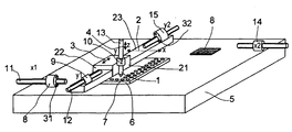
- the automatic pipetting device has a pipetting tool 1 which is divided into three Axes 2, 3, 4 in the x, y and z directions can be moved over a work surface 5 is.
- a substance bank plate 6 is arranged on the work surface 5 has several vessels 7 for substances. There is also a slide 8 arranged on the work surface 5, on which those contained in the plate 6 Substances should be applied.
- the pipetting tool is at the destination, a point on the slide 8 1 in turn for contact with adjustable end stops 14, 15 (x2, y2) brought, the drive for the actual movement of the pipetting tool is not shown.
- the pipetting tool 1 is attached to a holder 21 which is in the direction the z-axis is displaceable.
- This holder 21 is in turn on one Carriage 22 arranged, which in the y-axis direction 3 on a bar 23 is slidably mounted.
- the bar 23 in turn is not shown in FIG Way movably mounted and driven in the direction of the x-axis 2.
- the drive elements can be simple cylinders with pistons.
- Advantageous here is the low mass and the robustness of the drive elements, whereby the movements can be carried out particularly quickly. Because of the adjustable end stops can basically be based on a position feedback to be dispensed with, however, in the end stops 8, 15 Sensors 31, 32 for confirming the installation of the carriage 22 or the Bar 23 is provided at the end stops in order to recordings of a pipetting tool that is not yet in the end position to avoid.
- a hydraulic or pneumatic can be at the end stops Damping cylinders can be attached that allow the fast movement to be precise brakes to reach the respective preset stop and Prevents blows. This is not shown in the drawing.
- the main application is "reformatting" from parallel Analyzes to be carried out from microtiter plate format to a nano format with a few thousand analysis points e.g. on one for microscopy usual slides.
- the stepper motor-driven end stops x1 and y1 for example, set the Locations of the vessels 7 of the microtiter plate 6, which serve as the source for the pipetting substances is considered.
- the finely resolved end stops x2 and y2 determine the target locations on the slide.
- the Accuracy of resolution of the respective end stops depending on the required position accuracy. For example, for the Approach to the relatively roughly resolved (rasterized) vessels at the source less accuracy than at the high-resolution analysis points the slide at the destination. That possibility is compared to the previously known systems particularly advantageous.
Landscapes
- Immunology (AREA)
- Life Sciences & Earth Sciences (AREA)
- Pathology (AREA)
- Analytical Chemistry (AREA)
- Biochemistry (AREA)
- General Health & Medical Sciences (AREA)
- General Physics & Mathematics (AREA)
- Health & Medical Sciences (AREA)
- Physics & Mathematics (AREA)
- Chemical & Material Sciences (AREA)
- Sampling And Sample Adjustment (AREA)
- Automatic Analysis And Handling Materials Therefor (AREA)
- Feeding, Discharge, Calcimining, Fusing, And Gas-Generation Devices (AREA)
- Control Of Position Or Direction (AREA)
- Devices For Use In Laboratory Experiments (AREA)
- Supports For Pipes And Cables (AREA)
- Branch Pipes, Bends, And The Like (AREA)
- Blow-Moulding Or Thermoforming Of Plastics Or The Like (AREA)
- Cleaning In General (AREA)
Abstract
Description
Claims (9)
- Pipettierautomat mit einem Antrieb zur Bewegung eines Pipettierwerkzeuges (1) von einem Quellort an einen Zielort, dadurch gekennzeichnet, daß am Quell- und/oder Zielort automatisch feinjustierbare Endanschläge (8-10, 14, 15) für die vom Antrieb erzeugten Bewegungen des Pipettierwerkzeuges (1) vorgesehen sind.
- Pipettierautomat nach Anspruch 1, dadurch gekennzeichnet, daß an den Endanschlägen (8-10, 14, 15) Dämpfungsmittel angeordnet sind.
- Pipettierautomat nach einem der Ansprüche 1 oder 2, dadurch gekennzeichnet, daß der Antrieb als hydraulischer oder pneumatischer Linearantrieb ausgebildet ist.
- Pipettierautomat nach einem der Ansprüche 1 bis 3, dadurch gekennzeichnet, daß die Endanschläge (8-10, 14, 15) durch Schrittmotoren gesteuerte Anschlagsflächen aufweisen.
- Pipettierautomat nach einem der Ansprüche 1 bis 4, dadurch gekennzeichnet, daß an den Endanschlägen (8-10, 14, 15) Sensoren (31, 32) zur Lageerfassung angebracht sind.
- Pipettierautomat nach einem der Ansprüche 1 bis 5, dadurch gekennzeichnet, daß die Endanschläge (8, 9) des Quellortes gegenüber den Endanschlägen (14, 15) des Zielortes eine unterschiedliche Einstellgenauigkeit aufweisen.
- Verfahren zum automatischen Pipettieren, umfassend eine Aufnahme einer Substanz an einem Quellort und die Abgabe der Substanz an einem Zielort sowie die Bewegung des Pipettierwerkzeugs vom Quellzum Zielort, dadurch gekennzeichnet, daß vom Quellort ausgehend eine schnelle Bewegung des Pipetierwerkzeugs erfolgt und daß am Zielort lageveränderliche Endanschläge zwischenzeitlich in eine genaue Position gebracht werden, wobei die Bewegungen örtlich voneinander unabhängig sind.
- Verfahren nach Anspruch 7, dadurch gekennzeichnet, daß die schnelle Bewegung vor Erreichen des Endanschlags abgebremst wird.
- Verfahren nach Anspruch 7 oder 8, dadurch gekennzeichnet, daß nach Erreichen des Endanschlages die Lage des Pipettierwerkzeugs gemessen wird.
Applications Claiming Priority (2)
| Application Number | Priority Date | Filing Date | Title |
|---|---|---|---|
| DE19823283 | 1998-05-25 | ||
| DE19823283A DE19823283A1 (de) | 1998-05-25 | 1998-05-25 | Pipettierautomat |
Publications (3)
| Publication Number | Publication Date |
|---|---|
| EP0961118A2 true EP0961118A2 (de) | 1999-12-01 |
| EP0961118A3 EP0961118A3 (de) | 2003-05-21 |
| EP0961118B1 EP0961118B1 (de) | 2006-06-14 |
Family
ID=7868833
Family Applications (1)
| Application Number | Title | Priority Date | Filing Date |
|---|---|---|---|
| EP99109205A Expired - Lifetime EP0961118B1 (de) | 1998-05-25 | 1999-05-20 | Pipettierautomat |
Country Status (6)
| Country | Link |
|---|---|
| US (1) | US6234033B1 (de) |
| EP (1) | EP0961118B1 (de) |
| JP (1) | JP2000000477A (de) |
| AT (1) | ATE330228T1 (de) |
| CA (1) | CA2272183A1 (de) |
| DE (2) | DE19823283A1 (de) |
Cited By (3)
| Publication number | Priority date | Publication date | Assignee | Title |
|---|---|---|---|---|
| DE102008010267A1 (de) * | 2008-02-19 | 2009-08-20 | Nyársik, Lajos, Dr. | Pipettiervorrichtung für manuelle Flüssigkeitshandhabung |
| CN106799266A (zh) * | 2016-11-23 | 2017-06-06 | 中国计量大学 | 一种手持式移液器容量校准装置及校准方法 |
| CN108295914A (zh) * | 2017-01-11 | 2018-07-20 | 广州康昕瑞基因健康科技有限公司 | 移液针定位装置 |
Families Citing this family (13)
| Publication number | Priority date | Publication date | Assignee | Title |
|---|---|---|---|---|
| WO2001068259A1 (en) * | 2000-03-16 | 2001-09-20 | Biogenex Laboratories | Automated specimen processing apparatus with fluid detection |
| JP2004532983A (ja) * | 2001-05-03 | 2004-10-28 | アフィメトリックス インコーポレイテッド | 高スループットマイクロアレイスポッティングシステムおよび方法 |
| NZ533664A (en) * | 2001-12-24 | 2005-01-28 | Synthes Ag | Device for performing osteosynthesis |
| US20030213906A1 (en) * | 2002-05-20 | 2003-11-20 | Large Scale Proteomics Corporation | Method and apparatus for minimizing evaporation of a volatile substance |
| JP4351875B2 (ja) | 2003-07-15 | 2009-10-28 | シスメックス株式会社 | 液体吸引装置とそれを備えた分析装置 |
| US7396512B2 (en) | 2003-11-04 | 2008-07-08 | Drummond Scientific Company | Automatic precision non-contact open-loop fluid dispensing |
| US6988518B2 (en) * | 2004-06-02 | 2006-01-24 | Automation Techniques, Inc. | Robotic system and method for transport of materials with minimization of footprint size |
| US7284453B2 (en) * | 2005-07-15 | 2007-10-23 | Beckman Coulter, Inc. | Method and apparatus for maximizing liquid aspiration from small vessels |
| US20080003667A1 (en) * | 2006-05-19 | 2008-01-03 | Affymetrix, Inc. | Consumable elements for use with fluid processing and detection systems |
| US20100248981A1 (en) * | 2009-03-27 | 2010-09-30 | Affymetrix, Inc. | System and methods for processing microarrays |
| CN107076770B (zh) * | 2014-07-28 | 2019-07-12 | 道格拉斯科学有限责任公司 | 用于分析生物样本和试剂的仪器 |
| CN108406756A (zh) * | 2018-01-11 | 2018-08-17 | 佛山市南海区广工大数控装备协同创新研究院 | 一种柔性机器人及其控制方法 |
| CN113559949B (zh) * | 2021-08-02 | 2022-08-30 | 井冈山大学 | 一种生物制药用小分子新药研发装置 |
Family Cites Families (16)
| Publication number | Priority date | Publication date | Assignee | Title |
|---|---|---|---|---|
| US3228270A (en) * | 1963-05-21 | 1966-01-11 | New Britain Machine Co | Automatic feed mechanism for a machine tool |
| US3853008A (en) * | 1972-02-24 | 1974-12-10 | Beckman Instruments Inc | Liquid sample supply apparatus |
| US3870164A (en) * | 1972-07-12 | 1975-03-11 | Harold A Haase | Work transfer device |
| FR2459111A1 (fr) * | 1979-06-15 | 1981-01-09 | Sormel Sa | Automate de manipulation precise a cadence elevee |
| EP0189599B1 (de) * | 1984-12-27 | 1989-03-22 | Sumitomo Electric Industries Limited | Verfahren und Anlage zur Inkubation von Zellen |
| FR2612639B1 (fr) * | 1987-03-19 | 1990-05-11 | Ysebaert | Doseur de quantites liquides variables |
| FR2597607B1 (fr) * | 1987-04-10 | 1992-11-20 | Helena Lab Corp | Appareil applicateur automatique a pipettes |
| US5306510A (en) * | 1988-01-14 | 1994-04-26 | Cyberlab, Inc. | Automated pipetting system |
| DE3920476A1 (de) * | 1989-06-22 | 1991-01-03 | Hoechst Ag | Dosier- und fuellgeraet |
| WO1991016675A1 (en) * | 1990-04-06 | 1991-10-31 | Applied Biosystems, Inc. | Automated molecular biology laboratory |
| AU2266892A (en) * | 1991-06-13 | 1993-01-12 | Abbott Laboratories | Optical imaging for positioning and cell counting |
| US5906795A (en) * | 1996-04-08 | 1999-05-25 | Sanyo Electric Co., Ltd. | Pipetting apparatus |
| US6112905A (en) * | 1996-07-31 | 2000-09-05 | Aseco Corporation | Automatic semiconductor part handler |
| US5897837A (en) * | 1997-02-06 | 1999-04-27 | Toa Medical Electronics Co., Ltd. | Dispensing device and Immunoassay apparatus using the same |
| US5985214A (en) * | 1997-05-16 | 1999-11-16 | Aurora Biosciences Corporation | Systems and methods for rapidly identifying useful chemicals in liquid samples |
| US6132582A (en) * | 1998-09-14 | 2000-10-17 | The Perkin-Elmer Corporation | Sample handling system for a multi-channel capillary electrophoresis device |
-
1998
- 1998-05-25 DE DE19823283A patent/DE19823283A1/de not_active Withdrawn
-
1999
- 1999-04-29 US US09/301,578 patent/US6234033B1/en not_active Expired - Lifetime
- 1999-05-18 CA CA002272183A patent/CA2272183A1/en not_active Abandoned
- 1999-05-20 AT AT99109205T patent/ATE330228T1/de not_active IP Right Cessation
- 1999-05-20 EP EP99109205A patent/EP0961118B1/de not_active Expired - Lifetime
- 1999-05-20 DE DE59913542T patent/DE59913542D1/de not_active Expired - Lifetime
- 1999-05-21 JP JP11141896A patent/JP2000000477A/ja active Pending
Cited By (4)
| Publication number | Priority date | Publication date | Assignee | Title |
|---|---|---|---|---|
| DE102008010267A1 (de) * | 2008-02-19 | 2009-08-20 | Nyársik, Lajos, Dr. | Pipettiervorrichtung für manuelle Flüssigkeitshandhabung |
| CN106799266A (zh) * | 2016-11-23 | 2017-06-06 | 中国计量大学 | 一种手持式移液器容量校准装置及校准方法 |
| CN106799266B (zh) * | 2016-11-23 | 2018-12-25 | 中国计量大学 | 一种手持式移液器容量校准装置及校准方法 |
| CN108295914A (zh) * | 2017-01-11 | 2018-07-20 | 广州康昕瑞基因健康科技有限公司 | 移液针定位装置 |
Also Published As
| Publication number | Publication date |
|---|---|
| US6234033B1 (en) | 2001-05-22 |
| EP0961118A3 (de) | 2003-05-21 |
| EP0961118B1 (de) | 2006-06-14 |
| DE59913542D1 (de) | 2006-07-27 |
| DE19823283A1 (de) | 1999-12-02 |
| JP2000000477A (ja) | 2000-01-07 |
| ATE330228T1 (de) | 2006-07-15 |
| CA2272183A1 (en) | 1999-11-25 |
Similar Documents
| Publication | Publication Date | Title |
|---|---|---|
| EP0961118B1 (de) | Pipettierautomat | |
| DE4023311C2 (de) | ||
| DE212018000110U1 (de) | Schweißnagelabnahmevorrichtung für eine Vibrationsplatte | |
| EP0377187A2 (de) | Verfahren und Vorrichtung zum Vermessen der Form von Zylinderbohrungen in Werkstücken | |
| EP0789221B1 (de) | Verfahren und Vorrichtung zur koordinatenmässigen Vermessung von Werkstücken auf Bearbeitungsmaschinen | |
| DE102016203590A1 (de) | Messvorrichtung und Trägermechanismus eines säulenartigen Werkstücks | |
| DE102007019453B4 (de) | Koordinatenmessgerät mit zwei Schlitten auf gemeinsamer Führung | |
| EP0214500B1 (de) | Oberflächenprüfeinrichtung | |
| DE68906669T2 (de) | Messsystem fuer eine werkzeugeinstellung in einer werkzeugmaschine. | |
| EP1322909A1 (de) | Koordinatenmessgerät | |
| DE102018115745B4 (de) | Dreh-Schwenk-Mechanismus für ein Koordinatenmessgerät | |
| DE19623601A1 (de) | Tastkopf für Koordinatenmeßgeräte mit einer Klemmvorrichtung zur Klemmung des auslenkbaren Teils des Tastkopfes | |
| EP3405770B1 (de) | Messvorrichtung, messanordnung und verfahren zur ermittlung von messsignalen während einer eindringbewegung eines eindringkörpers in eine oberfläche eines prüfkörpers | |
| DE19929648A1 (de) | Antriebsanordnung für Meßinstrumente und Meßinstrument mit einer derartigen Antriebsanordnung | |
| DE10319711A1 (de) | Verfahren zur hochgenauen dimensionalen Messung an Messobjekten | |
| EP0603526A1 (de) | Verfahren und Vorrichtung zum elektroerosiven Bearbeiten | |
| DE2707960C2 (de) | ||
| EP1814700B1 (de) | Vorrichtung zum ankoppeln einer zusatzeinrichtung | |
| DD288872A5 (de) | Einkoordinatenmessgeraet | |
| DE19861469B4 (de) | Verfahren zur Kalibrierung eines Tasters eines Koordinatenmessgerätes | |
| DD222105A1 (de) | Anordnung zur positionierung von messobjekten bei waagerecht antastenden einkoordinatenmessgeraeten | |
| EP0744592B1 (de) | Verfahren und Vorrichtung zur Messung von Biegewinkeln von Blechteilen | |
| DE10124365A1 (de) | Vorrichtung und Verfahren zum Positionieren und/oder Fixieren eines Objektes | |
| CH659026A5 (de) | Profiliereinrichtung fuer eine schleifscheibe an einer zahnflankenschleifmaschine. | |
| DE102024124494A1 (de) | Messstand zum Bestimmen eines Messparameters eines optischen Prüflings |
Legal Events
| Date | Code | Title | Description |
|---|---|---|---|
| PUAI | Public reference made under article 153(3) epc to a published international application that has entered the european phase |
Free format text: ORIGINAL CODE: 0009012 |
|
| AK | Designated contracting states |
Kind code of ref document: A2 Designated state(s): AT BE CH CY DE DK ES FI FR GB GR IE IT LI LU MC NL PT SE |
|
| AX | Request for extension of the european patent |
Free format text: AL;LT;LV;MK;RO;SI |
|
| PUAL | Search report despatched |
Free format text: ORIGINAL CODE: 0009013 |
|
| RAP1 | Party data changed (applicant data changed or rights of an application transferred) |
Owner name: ABBOTT GMBH & CO. KG |
|
| AK | Designated contracting states |
Designated state(s): AT BE CH CY DE DK ES FI FR GB GR IE IT LI LU MC NL PT SE |
|
| AX | Request for extension of the european patent |
Extension state: AL LT LV MK RO SI |
|
| RIC1 | Information provided on ipc code assigned before grant |
Ipc: 7B 25J 9/02 B Ipc: 7B 25J 9/10 B Ipc: 7G 01N 35/10 A |
|
| 17P | Request for examination filed |
Effective date: 20031120 |
|
| AKX | Designation fees paid |
Designated state(s): AT BE CH DE DK ES FI FR GB GR IE IT LI NL PT SE |
|
| AXX | Extension fees paid |
Extension state: SI Payment date: 20031120 Extension state: RO Payment date: 20031120 |
|
| GRAP | Despatch of communication of intention to grant a patent |
Free format text: ORIGINAL CODE: EPIDOSNIGR1 |
|
| GRAS | Grant fee paid |
Free format text: ORIGINAL CODE: EPIDOSNIGR3 |
|
| GRAA | (expected) grant |
Free format text: ORIGINAL CODE: 0009210 |
|
| AK | Designated contracting states |
Kind code of ref document: B1 Designated state(s): AT BE CH DE DK ES FI FR GB GR IE IT LI NL PT SE |
|
| AX | Request for extension of the european patent |
Extension state: RO SI |
|
| PG25 | Lapsed in a contracting state [announced via postgrant information from national office to epo] |
Ref country code: NL Free format text: LAPSE BECAUSE OF FAILURE TO SUBMIT A TRANSLATION OF THE DESCRIPTION OR TO PAY THE FEE WITHIN THE PRESCRIBED TIME-LIMIT Effective date: 20060614 Ref country code: IT Free format text: LAPSE BECAUSE OF FAILURE TO SUBMIT A TRANSLATION OF THE DESCRIPTION OR TO PAY THE FEE WITHIN THE PRESCRIBED TIME-LIMIT;WARNING: LAPSES OF ITALIAN PATENTS WITH EFFECTIVE DATE BEFORE 2007 MAY HAVE OCCURRED AT ANY TIME BEFORE 2007. THE CORRECT EFFECTIVE DATE MAY BE DIFFERENT FROM THE ONE RECORDED. Effective date: 20060614 Ref country code: IE Free format text: LAPSE BECAUSE OF FAILURE TO SUBMIT A TRANSLATION OF THE DESCRIPTION OR TO PAY THE FEE WITHIN THE PRESCRIBED TIME-LIMIT Effective date: 20060614 Ref country code: FI Free format text: LAPSE BECAUSE OF FAILURE TO SUBMIT A TRANSLATION OF THE DESCRIPTION OR TO PAY THE FEE WITHIN THE PRESCRIBED TIME-LIMIT Effective date: 20060614 |
|
| REG | Reference to a national code |
Ref country code: GB Ref legal event code: FG4D Free format text: NOT ENGLISH |
|
| REG | Reference to a national code |
Ref country code: CH Ref legal event code: EP |
|
| REG | Reference to a national code |
Ref country code: IE Ref legal event code: FG4D Free format text: LANGUAGE OF EP DOCUMENT: GERMAN |
|
| REF | Corresponds to: |
Ref document number: 59913542 Country of ref document: DE Date of ref document: 20060727 Kind code of ref document: P |
|
| PG25 | Lapsed in a contracting state [announced via postgrant information from national office to epo] |
Ref country code: SE Free format text: LAPSE BECAUSE OF FAILURE TO SUBMIT A TRANSLATION OF THE DESCRIPTION OR TO PAY THE FEE WITHIN THE PRESCRIBED TIME-LIMIT Effective date: 20060914 Ref country code: DK Free format text: LAPSE BECAUSE OF FAILURE TO SUBMIT A TRANSLATION OF THE DESCRIPTION OR TO PAY THE FEE WITHIN THE PRESCRIBED TIME-LIMIT Effective date: 20060914 |
|
| PG25 | Lapsed in a contracting state [announced via postgrant information from national office to epo] |
Ref country code: ES Free format text: LAPSE BECAUSE OF FAILURE TO SUBMIT A TRANSLATION OF THE DESCRIPTION OR TO PAY THE FEE WITHIN THE PRESCRIBED TIME-LIMIT Effective date: 20060925 |
|
| GBT | Gb: translation of ep patent filed (gb section 77(6)(a)/1977) |
Effective date: 20060927 |
|
| PG25 | Lapsed in a contracting state [announced via postgrant information from national office to epo] |
Ref country code: PT Free format text: LAPSE BECAUSE OF FAILURE TO SUBMIT A TRANSLATION OF THE DESCRIPTION OR TO PAY THE FEE WITHIN THE PRESCRIBED TIME-LIMIT Effective date: 20061114 |
|
| NLV1 | Nl: lapsed or annulled due to failure to fulfill the requirements of art. 29p and 29m of the patents act | ||
| PLBE | No opposition filed within time limit |
Free format text: ORIGINAL CODE: 0009261 |
|
| STAA | Information on the status of an ep patent application or granted ep patent |
Free format text: STATUS: NO OPPOSITION FILED WITHIN TIME LIMIT |
|
| EN | Fr: translation not filed | ||
| 26N | No opposition filed |
Effective date: 20070315 |
|
| BERE | Be: lapsed |
Owner name: ABBOTT G.M.B.H. & CO. KG Effective date: 20070531 |
|
| REG | Reference to a national code |
Ref country code: CH Ref legal event code: PL |
|
| PG25 | Lapsed in a contracting state [announced via postgrant information from national office to epo] |
Ref country code: LI Free format text: LAPSE BECAUSE OF NON-PAYMENT OF DUE FEES Effective date: 20070531 Ref country code: CH Free format text: LAPSE BECAUSE OF NON-PAYMENT OF DUE FEES Effective date: 20070531 |
|
| PG25 | Lapsed in a contracting state [announced via postgrant information from national office to epo] |
Ref country code: BE Free format text: LAPSE BECAUSE OF NON-PAYMENT OF DUE FEES Effective date: 20070531 |
|
| PG25 | Lapsed in a contracting state [announced via postgrant information from national office to epo] |
Ref country code: GR Free format text: LAPSE BECAUSE OF FAILURE TO SUBMIT A TRANSLATION OF THE DESCRIPTION OR TO PAY THE FEE WITHIN THE PRESCRIBED TIME-LIMIT Effective date: 20060915 Ref country code: FR Free format text: LAPSE BECAUSE OF FAILURE TO SUBMIT A TRANSLATION OF THE DESCRIPTION OR TO PAY THE FEE WITHIN THE PRESCRIBED TIME-LIMIT Effective date: 20070309 |
|
| PG25 | Lapsed in a contracting state [announced via postgrant information from national office to epo] |
Ref country code: AT Free format text: LAPSE BECAUSE OF NON-PAYMENT OF DUE FEES Effective date: 20070520 |
|
| PG25 | Lapsed in a contracting state [announced via postgrant information from national office to epo] |
Ref country code: FR Free format text: LAPSE BECAUSE OF FAILURE TO SUBMIT A TRANSLATION OF THE DESCRIPTION OR TO PAY THE FEE WITHIN THE PRESCRIBED TIME-LIMIT Effective date: 20060614 |
|
| PGFP | Annual fee paid to national office [announced via postgrant information from national office to epo] |
Ref country code: GB Payment date: 20130425 Year of fee payment: 15 Ref country code: DE Payment date: 20130531 Year of fee payment: 15 |
|
| REG | Reference to a national code |
Ref country code: DE Ref legal event code: R082 Ref document number: 59913542 Country of ref document: DE Representative=s name: PATENTANWAELTE ISENBRUCK BOESL HOERSCHLER LLP, DE |
|
| REG | Reference to a national code |
Ref country code: DE Ref legal event code: R082 Ref document number: 59913542 Country of ref document: DE Representative=s name: PATENTANWAELTE ISENBRUCK BOESL HOERSCHLER LLP, DE Effective date: 20130827 Ref country code: DE Ref legal event code: R081 Ref document number: 59913542 Country of ref document: DE Owner name: ABBVIE DEUTSCHLAND GMBH & CO. KG, DE Free format text: FORMER OWNER: ABBOTT GMBH & CO. KG, 65205 WIESBADEN, DE Effective date: 20130827 |
|
| REG | Reference to a national code |
Ref country code: GB Ref legal event code: 732E Free format text: REGISTERED BETWEEN 20131003 AND 20131009 |
|
| REG | Reference to a national code |
Ref country code: DE Ref legal event code: R119 Ref document number: 59913542 Country of ref document: DE |
|
| GBPC | Gb: european patent ceased through non-payment of renewal fee |
Effective date: 20140520 |
|
| REG | Reference to a national code |
Ref country code: DE Ref legal event code: R119 Ref document number: 59913542 Country of ref document: DE Effective date: 20141202 |
|
| PG25 | Lapsed in a contracting state [announced via postgrant information from national office to epo] |
Ref country code: DE Free format text: LAPSE BECAUSE OF NON-PAYMENT OF DUE FEES Effective date: 20141202 |
|
| PG25 | Lapsed in a contracting state [announced via postgrant information from national office to epo] |
Ref country code: GB Free format text: LAPSE BECAUSE OF NON-PAYMENT OF DUE FEES Effective date: 20140520 |