EP0961192A2 - Dispositif de commande - Google Patents
Dispositif de commande Download PDFInfo
- Publication number
- EP0961192A2 EP0961192A2 EP99110209A EP99110209A EP0961192A2 EP 0961192 A2 EP0961192 A2 EP 0961192A2 EP 99110209 A EP99110209 A EP 99110209A EP 99110209 A EP99110209 A EP 99110209A EP 0961192 A2 EP0961192 A2 EP 0961192A2
- Authority
- EP
- European Patent Office
- Prior art keywords
- control
- valve
- shaft
- line
- pump
- Prior art date
- Legal status (The legal status is an assumption and is not a legal conclusion. Google has not performed a legal analysis and makes no representation as to the accuracy of the status listed.)
- Withdrawn
Links
Images


Classifications
-
- F—MECHANICAL ENGINEERING; LIGHTING; HEATING; WEAPONS; BLASTING
- F15—FLUID-PRESSURE ACTUATORS; HYDRAULICS OR PNEUMATICS IN GENERAL
- F15B—SYSTEMS ACTING BY MEANS OF FLUIDS IN GENERAL; FLUID-PRESSURE ACTUATORS, e.g. SERVOMOTORS; DETAILS OF FLUID-PRESSURE SYSTEMS, NOT OTHERWISE PROVIDED FOR
- F15B13/00—Details of servomotor systems ; Valves for servomotor systems
- F15B13/02—Fluid distribution or supply devices characterised by their adaptation to the control of servomotors
- F15B13/04—Fluid distribution or supply devices characterised by their adaptation to the control of servomotors for use with a single servomotor
- F15B13/0401—Valve members; Fluid interconnections therefor
- F15B13/0405—Valve members; Fluid interconnections therefor for seat valves, i.e. poppet valves
-
- F—MECHANICAL ENGINEERING; LIGHTING; HEATING; WEAPONS; BLASTING
- F15—FLUID-PRESSURE ACTUATORS; HYDRAULICS OR PNEUMATICS IN GENERAL
- F15B—SYSTEMS ACTING BY MEANS OF FLUIDS IN GENERAL; FLUID-PRESSURE ACTUATORS, e.g. SERVOMOTORS; DETAILS OF FLUID-PRESSURE SYSTEMS, NOT OTHERWISE PROVIDED FOR
- F15B13/00—Details of servomotor systems ; Valves for servomotor systems
- F15B13/02—Fluid distribution or supply devices characterised by their adaptation to the control of servomotors
- F15B13/04—Fluid distribution or supply devices characterised by their adaptation to the control of servomotors for use with a single servomotor
- F15B13/044—Fluid distribution or supply devices characterised by their adaptation to the control of servomotors for use with a single servomotor operated by electrically-controlled means, e.g. solenoids, torque-motors
- F15B13/0444—Fluid distribution or supply devices characterised by their adaptation to the control of servomotors for use with a single servomotor operated by electrically-controlled means, e.g. solenoids, torque-motors with rotary electric motor
-
- F—MECHANICAL ENGINEERING; LIGHTING; HEATING; WEAPONS; BLASTING
- F15—FLUID-PRESSURE ACTUATORS; HYDRAULICS OR PNEUMATICS IN GENERAL
- F15B—SYSTEMS ACTING BY MEANS OF FLUIDS IN GENERAL; FLUID-PRESSURE ACTUATORS, e.g. SERVOMOTORS; DETAILS OF FLUID-PRESSURE SYSTEMS, NOT OTHERWISE PROVIDED FOR
- F15B15/00—Fluid-actuated devices for displacing a member from one position to another; Gearing associated therewith
- F15B15/18—Combined units comprising both motor and pump
Definitions
- the invention is based on the object Generic control device according to the Form the generic term so that it is dependent is automatically controlled by the direction of rotation.
- a control for the invention alternating switching of two valves provided that simple, practical and insensitive to faults is, at the same time a minimum of space necessary is.
- the first and second controlled valve of the valve device each as 3/2 valve and both valves to form the Overall valve device as a 4/2 valve educated.
- the axial displacement movement of the Control axis on a acting as a valve spool Valve sealing element that is transferred from the pump incoming line in one switch position only with the one, e.g. leading to the one cylinder space Line and in the other switch position only with the others, e.g. leading to the other cylinder space Line connects, but not to the Pump connected line connected to the tank is.
- the valve sealing element only moves with very little force of a spring on the Control area (mouths of the three lines) pressed.
- This pressure force is further increased by a hydraulic force acting in the same direction amplified, which is caused by the two hydraulically effective surfaces, namely the front Pressure area of the valve sealing element is smaller than that rear, hydraulically effective cross-sectional area is, this front and back through the in the recess provided bore are connected.
- a linear guide arranged in the hollow body in turn on the back of a housing-fixed, supports plane abutments.
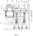
- FIG 1 is a schematic cross section Hydraulic piston-cylinder unit 10 side with an eye hole 11 for mechanical connection shown, in addition to a combined drive and Control unit 12 is provided.
- This has one reversible, designated 13 in total Electric motor, the motor shaft 14 as Actuating shaft 15 ( Figures 2 and 4) one Actuator with one in the axial direction Control rod movable between 2 switch positions 16 is formed.
- the actuating shaft 15 and the Control rod 16 are in a thread-like Active connection, the first embodiment in the Figures 2 and 3 and their alternative embodiment this is shown in Figure 4.
- FIG. 4 there is one axial blind bore 17 in the control rod 16 with an internal thread 18 is provided, one to this adapted external thread 19 of the actuating shaft 15 is provided. After that in the blind bore 17th external thread screwed in via the internal thread 18 19 only a certain stroke (few threads) can perform during the first rotary motion the actuating shaft 15, first the control rod 16 shifted in the axial direction. If the Actuating shaft 15 reached the end of the thread or has come into contact at the end of the blind hole, she takes the control rod 16 in one or the other direction of rotation with.
- the control lever 39 is as a tilt bearing 41st movable, two-armed lever formed, the an actuating arm 42 a control connection of a formed as the first valve 44 valve device acts while the other operating arm 43 the another control connection of a second valve 45 the Valve device releases and vice versa.
- Both that first valve 44 of the valve device as well second valve 45 are 3/2 and both are together be designed as a 4/2 valve. In any case it is a seat-sealed directional valve.
- the valve 44 is an example below described, which has the same structure as that valve 45.
- the first valve 44 with two on one seat overlying balls 441 and 442 provided, which over a control rod 443 alternately from the seat can be lifted off, the control rod 443 with radial play in a bore 444 and where this is connected to the first connection 445, the over the one of the two balls either with the Pump pressure leading line 46 or over the other of the two balls with the line leading to the tank 446 is connectable.
- the same design applies to the second valve 45. The same parts are therefore obtained the last of the three-digit reference number Digit.
Landscapes
- Engineering & Computer Science (AREA)
- Physics & Mathematics (AREA)
- Fluid Mechanics (AREA)
- Mechanical Engineering (AREA)
- General Engineering & Computer Science (AREA)
- Mechanically-Actuated Valves (AREA)
- Mechanical Control Devices (AREA)
Priority Applications (1)
| Application Number | Priority Date | Filing Date | Title |
|---|---|---|---|
| EP04024698A EP1505468B1 (fr) | 1998-05-28 | 1999-05-26 | Dispositif de commande |
Applications Claiming Priority (6)
| Application Number | Priority Date | Filing Date | Title |
|---|---|---|---|
| DE19823949 | 1998-05-28 | ||
| DE19823949 | 1998-05-28 | ||
| DE19827441 | 1998-06-19 | ||
| DE19827441 | 1998-06-19 | ||
| DE19832306A DE19832306C2 (de) | 1998-06-19 | 1998-07-17 | Vorrichtung mit einer Steuerstange und mit einem von dieser betätigten Steuerhebel |
| DE19832306 | 1998-07-17 |
Related Child Applications (1)
| Application Number | Title | Priority Date | Filing Date |
|---|---|---|---|
| EP04024698A Division EP1505468B1 (fr) | 1998-05-28 | 1999-05-26 | Dispositif de commande |
Publications (2)
| Publication Number | Publication Date |
|---|---|
| EP0961192A2 true EP0961192A2 (fr) | 1999-12-01 |
| EP0961192A3 EP0961192A3 (fr) | 2004-04-21 |
Family
ID=27218404
Family Applications (1)
| Application Number | Title | Priority Date | Filing Date |
|---|---|---|---|
| EP99110209A Withdrawn EP0961192A3 (fr) | 1998-05-28 | 1999-05-26 | Dispositif de commande |
Country Status (3)
| Country | Link |
|---|---|
| EP (1) | EP0961192A3 (fr) |
| DE (1) | DE59913690D1 (fr) |
| TR (1) | TR199901210A2 (fr) |
Cited By (1)
| Publication number | Priority date | Publication date | Assignee | Title |
|---|---|---|---|---|
| CN103267162A (zh) * | 2013-05-09 | 2013-08-28 | 浙江精嘉阀门有限公司 | 超超临界快关蝶阀液控装置 |
Family Cites Families (13)
| Publication number | Priority date | Publication date | Assignee | Title |
|---|---|---|---|---|
| DE687918C (de) * | 1936-07-22 | 1940-02-08 | Theodor Wedde | Getriebe zur Umwandlung einer hin und her gehenden Bewegung in eine Drehbewegung |
| US2679727A (en) * | 1951-04-16 | 1954-06-01 | Detroit Harvester Co | Hydraulic power unit |
| FR1249404A (fr) * | 1959-11-14 | 1960-12-30 | Rech Etudes Production Sarl | Vérin hydraulique autonome à alimentation électrique et à commande électrique |
| US3277736A (en) * | 1964-07-27 | 1966-10-11 | Goodman Robert | Device for translating rotary motion into linear motion |
| JPS5129440Y1 (fr) * | 1970-12-26 | 1976-07-24 | ||
| CH657433A5 (de) * | 1981-09-14 | 1986-08-29 | Sig Schweiz Industrieges | Vorrichtung zur begrenzung des drehwinkels bei schraubengetrieben und fluidische regeleinrichtung. |
| US4509379A (en) * | 1982-05-03 | 1985-04-09 | Westmoreland Julius C | Rotary to reciprocating motion converter |
| FR2567979B1 (fr) * | 1984-07-18 | 1986-12-19 | Somfy | Actionneur lineaire a systeme vis-ecrou |
| US4765370A (en) * | 1985-11-29 | 1988-08-23 | Fujikura Rubber Ltd. | Directional control valve |
| WO1987005368A1 (fr) * | 1986-03-06 | 1987-09-11 | Koeppen Detlef | Ensemble cylindre/pompe actionne par un milieu pressurise |
| FR2599780B1 (fr) * | 1986-06-04 | 1988-09-09 | Somfy | Dispositif d'actionnement electromecanique pour porte a deplacement coulissant |
| JPH04317537A (ja) * | 1991-04-17 | 1992-11-09 | Fuji Electric Co Ltd | 電動機を備えるねじ伝動装置 |
| JP2547230Y2 (ja) * | 1991-05-15 | 1997-09-10 | 日東工器株式会社 | 油圧作動機 |
-
1999
- 1999-05-26 DE DE59913690T patent/DE59913690D1/de not_active Expired - Fee Related
- 1999-05-26 EP EP99110209A patent/EP0961192A3/fr not_active Withdrawn
- 1999-05-28 TR TR1999/01210A patent/TR199901210A2/xx unknown
Non-Patent Citations (1)
| Title |
|---|
| None |
Cited By (2)
| Publication number | Priority date | Publication date | Assignee | Title |
|---|---|---|---|---|
| CN103267162A (zh) * | 2013-05-09 | 2013-08-28 | 浙江精嘉阀门有限公司 | 超超临界快关蝶阀液控装置 |
| CN103267162B (zh) * | 2013-05-09 | 2015-05-20 | 浙江精嘉阀门有限公司 | 超超临界快关蝶阀液控装置 |
Also Published As
| Publication number | Publication date |
|---|---|
| EP0961192A3 (fr) | 2004-04-21 |
| TR199901210A2 (xx) | 2001-09-21 |
| DE59913690D1 (de) | 2006-08-31 |
Similar Documents
| Publication | Publication Date | Title |
|---|---|---|
| DE2340663A1 (de) | Servogesteuerte, hydraulische kraftuebertragungsvorrichtung | |
| DE2729404C2 (fr) | ||
| DE3939488C2 (de) | Hydrostatische Axialkolbenmaschine | |
| DE19902107A1 (de) | Verdrängungssteuervorrichtung für eine verstellbare Hydraulikeinheit | |
| DE2832981C2 (de) | Vorschubzylinder | |
| EP0772412A1 (fr) | Dispositif d'arret a systeme de freinage progressif | |
| DE19822439A1 (de) | Vorrichtung zur Durchführung von Betätigungen in einer Druckmaschine | |
| EP1437519A1 (fr) | Maítre-cylindre pour système de debrayage | |
| EP2102524A2 (fr) | Frein à disque comportant un actionneur à moteur électrique de type auto-amplifié | |
| DE19832306C2 (de) | Vorrichtung mit einer Steuerstange und mit einem von dieser betätigten Steuerhebel | |
| WO2006117080A1 (fr) | Dispositif de reglage pour un moteur a combustion interne | |
| EP1130293A2 (fr) | Dispositif de commande pour boítes de vitesses automatisées de véhicules | |
| EP0961192A2 (fr) | Dispositif de commande | |
| EP1505468B1 (fr) | Dispositif de commande | |
| DE3711384C2 (de) | Hydraulische Antriebsvorrichtung | |
| DE19620654A1 (de) | Verstellbare Axialkolbenmaschine in Schrägscheibenbauweise | |
| EP1225343A1 (fr) | Dispositif d'entrainement par vérin à pression fluidique | |
| DE10139222B4 (de) | Schwingungsdäpfer mit verstellbarer Dämpfkraft | |
| EP0444500B1 (fr) | Outil de fermeture pour capuchons de scellage de fûts | |
| CH671354A5 (de) | Blechbearbeitungsmaschine, insbesondere zum scheren oder abkanten von blech. | |
| DE19905626A1 (de) | Stellzylinder sowie Verfahren zum Einstellen eines Stellzylinders | |
| DE19912906B4 (de) | Hydraulischer Stellantrieb | |
| DE69810397T2 (de) | Schliess- und oder Öffnungsanordnung für Türen | |
| DE102006006684A1 (de) | Antriebseinheit für Hydraulik-Kolbenpumpen mit Exzenter eines Fahrzeugbremssystems | |
| DE20209151U1 (de) | Bremsvorrichtung sowie damit ausgestatteter fluidbetätigter Arbeitszylinder |
Legal Events
| Date | Code | Title | Description |
|---|---|---|---|
| PUAI | Public reference made under article 153(3) epc to a published international application that has entered the european phase |
Free format text: ORIGINAL CODE: 0009012 |
|
| AK | Designated contracting states |
Kind code of ref document: A2 Designated state(s): AT BE CH CY DE DK ES FI FR GB GR IE IT LI LU MC NL PT SE |
|
| AX | Request for extension of the european patent |
Free format text: AL;LT;LV;MK;RO;SI |
|
| RIC1 | Information provided on ipc code assigned before grant |
Ipc: 7F 16H 25/20 B Ipc: 7F 15B 15/18 B Ipc: 7G 05G 9/10 A |
|
| PUAL | Search report despatched |
Free format text: ORIGINAL CODE: 0009013 |
|
| AK | Designated contracting states |
Kind code of ref document: A3 Designated state(s): AT BE CH CY DE DK ES FI FR GB GR IE IT LI LU MC NL PT SE |
|
| AX | Request for extension of the european patent |
Extension state: AL LT LV MK RO SI |
|
| AKX | Designation fees paid |
Designated state(s): DE FR IT NL SE |
|
| STAA | Information on the status of an ep patent application or granted ep patent |
Free format text: STATUS: THE APPLICATION IS DEEMED TO BE WITHDRAWN |
|
| 18D | Application deemed to be withdrawn |
Effective date: 20041022 |