EP0961235A2 - Bandpeicher- und Zuführmechanismus für Frankiermaschinen - Google Patents
Bandpeicher- und Zuführmechanismus für Frankiermaschinen Download PDFInfo
- Publication number
- EP0961235A2 EP0961235A2 EP99108574A EP99108574A EP0961235A2 EP 0961235 A2 EP0961235 A2 EP 0961235A2 EP 99108574 A EP99108574 A EP 99108574A EP 99108574 A EP99108574 A EP 99108574A EP 0961235 A2 EP0961235 A2 EP 0961235A2
- Authority
- EP
- European Patent Office
- Prior art keywords
- tape
- feeding
- storing
- feeding mechanism
- print head
- Prior art date
- Legal status (The legal status is an assumption and is not a legal conclusion. Google has not performed a legal analysis and makes no representation as to the accuracy of the status listed.)
- Withdrawn
Links
- 230000007246 mechanism Effects 0.000 title claims abstract description 67
- 238000007639 printing Methods 0.000 claims abstract description 69
- 238000011144 upstream manufacturing Methods 0.000 claims description 27
- 238000003860 storage Methods 0.000 claims description 12
- 238000000034 method Methods 0.000 claims description 10
- 230000002452 interceptive effect Effects 0.000 claims description 6
- 238000005520 cutting process Methods 0.000 claims description 3
- 241000269627 Amphiuma means Species 0.000 claims 1
- 238000005516 engineering process Methods 0.000 abstract description 15
- 230000001133 acceleration Effects 0.000 abstract description 3
- 230000035939 shock Effects 0.000 abstract description 3
- 239000000976 ink Substances 0.000 description 46
- 238000007641 inkjet printing Methods 0.000 description 6
- 238000010276 construction Methods 0.000 description 5
- 238000005303 weighing Methods 0.000 description 5
- 238000000465 moulding Methods 0.000 description 4
- 230000002441 reversible effect Effects 0.000 description 4
- 238000007789 sealing Methods 0.000 description 4
- 238000012546 transfer Methods 0.000 description 3
- 238000011161 development Methods 0.000 description 2
- 239000000463 material Substances 0.000 description 2
- 239000004033 plastic Substances 0.000 description 2
- 238000003825 pressing Methods 0.000 description 2
- 230000008569 process Effects 0.000 description 2
- 239000002699 waste material Substances 0.000 description 2
- OKTJSMMVPCPJKN-UHFFFAOYSA-N Carbon Chemical compound [C] OKTJSMMVPCPJKN-UHFFFAOYSA-N 0.000 description 1
- 239000004677 Nylon Substances 0.000 description 1
- 230000000712 assembly Effects 0.000 description 1
- 238000000429 assembly Methods 0.000 description 1
- 229910052799 carbon Inorganic materials 0.000 description 1
- 230000008859 change Effects 0.000 description 1
- 230000006835 compression Effects 0.000 description 1
- 238000007906 compression Methods 0.000 description 1
- 238000001816 cooling Methods 0.000 description 1
- 230000000994 depressogenic effect Effects 0.000 description 1
- 238000013461 design Methods 0.000 description 1
- 238000003708 edge detection Methods 0.000 description 1
- 230000000694 effects Effects 0.000 description 1
- 239000011521 glass Substances 0.000 description 1
- 230000005484 gravity Effects 0.000 description 1
- 238000012423 maintenance Methods 0.000 description 1
- 239000002184 metal Substances 0.000 description 1
- 239000000203 mixture Substances 0.000 description 1
- 239000002991 molded plastic Substances 0.000 description 1
- 238000012544 monitoring process Methods 0.000 description 1
- 229920001778 nylon Polymers 0.000 description 1
- 230000002035 prolonged effect Effects 0.000 description 1
- 238000010926 purge Methods 0.000 description 1
- 230000000717 retained effect Effects 0.000 description 1
- 238000000926 separation method Methods 0.000 description 1
- 239000007787 solid Substances 0.000 description 1
- 230000003068 static effect Effects 0.000 description 1
- 230000007704 transition Effects 0.000 description 1
Images




Classifications
-
- B—PERFORMING OPERATIONS; TRANSPORTING
- B41—PRINTING; LINING MACHINES; TYPEWRITERS; STAMPS
- B41J—TYPEWRITERS; SELECTIVE PRINTING MECHANISMS, i.e. MECHANISMS PRINTING OTHERWISE THAN FROM A FORME; CORRECTION OF TYPOGRAPHICAL ERRORS
- B41J11/00—Devices or arrangements of selective printing mechanisms, e.g. ink-jet printers or thermal printers, for supporting or handling copy material in sheet or web form
- B41J11/66—Applications of cutting devices
- B41J11/70—Applications of cutting devices cutting perpendicular to the direction of paper feed
- B41J11/703—Cutting of tape
-
- B—PERFORMING OPERATIONS; TRANSPORTING
- B41—PRINTING; LINING MACHINES; TYPEWRITERS; STAMPS
- B41J—TYPEWRITERS; SELECTIVE PRINTING MECHANISMS, i.e. MECHANISMS PRINTING OTHERWISE THAN FROM A FORME; CORRECTION OF TYPOGRAPHICAL ERRORS
- B41J15/00—Devices or arrangements of selective printing mechanisms, e.g. ink-jet printers or thermal printers, specially adapted for supporting or handling copy material in continuous form, e.g. webs
- B41J15/005—Forming loops or sags in webs, e.g. for slackening a web or for compensating variations of the amount of conveyed web material (by arranging a "dancing roller" in a sag of the web material)
-
- B—PERFORMING OPERATIONS; TRANSPORTING
- B41—PRINTING; LINING MACHINES; TYPEWRITERS; STAMPS
- B41J—TYPEWRITERS; SELECTIVE PRINTING MECHANISMS, i.e. MECHANISMS PRINTING OTHERWISE THAN FROM A FORME; CORRECTION OF TYPOGRAPHICAL ERRORS
- B41J15/00—Devices or arrangements of selective printing mechanisms, e.g. ink-jet printers or thermal printers, specially adapted for supporting or handling copy material in continuous form, e.g. webs
- B41J15/04—Supporting, feeding, or guiding devices; Mountings for web rolls or spindles
-
- G—PHYSICS
- G07—CHECKING-DEVICES
- G07B—TICKET-ISSUING APPARATUS; FARE-REGISTERING APPARATUS; FRANKING APPARATUS
- G07B17/00—Franking apparatus
- G07B17/00185—Details internally of apparatus in a franking system, e.g. franking machine at customer or apparatus at post office
- G07B17/00193—Constructional details of apparatus in a franking system
-
- G—PHYSICS
- G07—CHECKING-DEVICES
- G07B—TICKET-ISSUING APPARATUS; FARE-REGISTERING APPARATUS; FRANKING APPARATUS
- G07B17/00—Franking apparatus
- G07B17/00459—Details relating to mailpieces in a franking system
- G07B17/00508—Printing or attaching on mailpieces
-
- G—PHYSICS
- G07—CHECKING-DEVICES
- G07B—TICKET-ISSUING APPARATUS; FARE-REGISTERING APPARATUS; FRANKING APPARATUS
- G07B17/00—Franking apparatus
- G07B17/00185—Details internally of apparatus in a franking system, e.g. franking machine at customer or apparatus at post office
- G07B17/00193—Constructional details of apparatus in a franking system
- G07B2017/0025—Storage of, e.g. ribbon
-
- G—PHYSICS
- G07—CHECKING-DEVICES
- G07B—TICKET-ISSUING APPARATUS; FARE-REGISTERING APPARATUS; FRANKING APPARATUS
- G07B17/00—Franking apparatus
- G07B17/00459—Details relating to mailpieces in a franking system
- G07B17/00508—Printing or attaching on mailpieces
- G07B2017/00516—Details of printing apparatus
- G07B2017/00524—Printheads
- G07B2017/00532—Inkjet
-
- G—PHYSICS
- G07—CHECKING-DEVICES
- G07B—TICKET-ISSUING APPARATUS; FARE-REGISTERING APPARATUS; FRANKING APPARATUS
- G07B17/00—Franking apparatus
- G07B17/00459—Details relating to mailpieces in a franking system
- G07B17/00508—Printing or attaching on mailpieces
- G07B2017/00516—Details of printing apparatus
- G07B2017/00556—Ensuring quality of print
-
- G—PHYSICS
- G07—CHECKING-DEVICES
- G07B—TICKET-ISSUING APPARATUS; FARE-REGISTERING APPARATUS; FRANKING APPARATUS
- G07B17/00—Franking apparatus
- G07B17/00459—Details relating to mailpieces in a franking system
- G07B17/00508—Printing or attaching on mailpieces
- G07B2017/00612—Attaching item on mailpiece
- G07B2017/0062—Label
-
- Y—GENERAL TAGGING OF NEW TECHNOLOGICAL DEVELOPMENTS; GENERAL TAGGING OF CROSS-SECTIONAL TECHNOLOGIES SPANNING OVER SEVERAL SECTIONS OF THE IPC; TECHNICAL SUBJECTS COVERED BY FORMER USPC CROSS-REFERENCE ART COLLECTIONS [XRACs] AND DIGESTS
- Y10—TECHNICAL SUBJECTS COVERED BY FORMER USPC
- Y10T—TECHNICAL SUBJECTS COVERED BY FORMER US CLASSIFICATION
- Y10T83/00—Cutting
- Y10T83/081—With randomly actuated stopping means
- Y10T83/088—Responsive to tool detector or work-feed-means detector
-
- Y—GENERAL TAGGING OF NEW TECHNOLOGICAL DEVELOPMENTS; GENERAL TAGGING OF CROSS-SECTIONAL TECHNOLOGIES SPANNING OVER SEVERAL SECTIONS OF THE IPC; TECHNICAL SUBJECTS COVERED BY FORMER USPC CROSS-REFERENCE ART COLLECTIONS [XRACs] AND DIGESTS
- Y10—TECHNICAL SUBJECTS COVERED BY FORMER USPC
- Y10T—TECHNICAL SUBJECTS COVERED BY FORMER US CLASSIFICATION
- Y10T83/00—Cutting
- Y10T83/202—With product handling means
- Y10T83/2074—Including means to divert one portion of product from another
- Y10T83/2083—Deflecting guide
Definitions
- This invention relates generally to the field of ink jet printing, and more particularly to mailing machines which incorporate ink jet technology and have the capability of printing postage indicia either on envelopes fed successively through the mailing machine or on discrete lengths of tape that is stored in and dispensed from the mailing machine and then manually affixed to bulky mail pieces or packages.
- Mailing machines of this type typically include an elongated feed deck, an envelope conveyor mechanism extending along the feed deck, a hopper for holding a stack of envelopes with the flaps still open, a flap closing and sealing device located just downstream from the hopper, and a postage meter mounted over the feed deck just downstream from the flap closing and sealing device.
- the postage meter typically includes an accounting device for monitoring the amount of postage dispensed and a printing device for printing a postage indicia on the envelopes as they are fed along the feed deck.
- the postage meter further includes a postage amount setting mechanism by which the postage meter is manually set to print an appropriate amount of postage as required by the weight of the envelopes being fed through the mailing machine.
- a postage amount setting mechanism by which the postage meter is manually set to print an appropriate amount of postage as required by the weight of the envelopes being fed through the mailing machine.
- Some of the more sophisticated mailing machines include an envelope weighing device interposed between the flap closing and sealing device for weighing each envelope as it passes over the weighing device and the postage meter for automatically setting the postage to print an appropriate amount of postage in the postage indicia.
- the printing devices therein have utilized ink transfer technology, in which ink is transferred from a storage device to a rotary or flat bed printing die of the printing device, and the ink then being transferred from the printing die to the envelope, either by rotation of a curved printing die while the envelope is in motion, or by suitably pressing the envelope against the flat bed printing die.
- ink transfer technology in which ink is transferred from a storage device to a rotary or flat bed printing die of the printing device, and the ink then being transferred from the printing die to the envelope, either by rotation of a curved printing die while the envelope is in motion, or by suitably pressing the envelope against the flat bed printing die.
- the item being printed upon does not vary in thickness so that as long as the sheet remains flat on the supporting surface, there will be no variation in the gap between the printing surface and the plane of the ink jet nozzles.
- conventional printers utilize a motor to drive the roll and then feed the tape web across the print means.
- the orientation of the motor connected to the roll employs a larger motor such that the inertia of the roll can be overcome.
- these large motors are expensive and, due to the large force, may tear or inconsistently feed the tape web.
- the printed postage indicia is relatively small in relation to the surface area of an envelope, there is ample surface area available for engagement with the envelope of various types of feeding mechanisms to move the envelope through the mailing machine after printing occurs without running the risk of smearing the ink within the postage indicia area by contact with any part of the feeding mechanisms.
- the size of the postage indicia is such that it occupies a major portion of the height of the strip of tape, thereby leaving very little marginal portion of the tape for contact with any portion of a tape feeding mechanism for moving the tape forwardly for printing and severing and then backwards to realign the new leading edge of the tape with the beginning of a printing location.
- the present invention substantially obviates, if not entirely eliminates, the problems associated with the feeding of tape within a mailing machine, or other ink jet printer, for the purpose of printing a postage indicia, or other indicia, thereon utilizing ink jet technology.
- the present invention addresses each of the problems mentioned above in connection with the design of an effective tape storing and feeding mechanism for use in a mailing machine utilizing ink jet technology for printing a postage indicia on the tape.
- the present invention provides a tape storing and feeding device which effectively maintains the proper critical gap between the surface of the tape being printed upon and the plane of the ink jet nozzles in order to achieve the necessary degree of print quality, which provides a tape feeding mechanism that effectively moves the tape in both forward and reverse directions without contacting any portion of the printed postage indicia and smearing the ink thereon, and provides an effective solution to the problem of tearing the tape due to sudden acceleration of the tape in order to maintain a high speed of operation of the mailing machine.
- the present invention is a tape storing and feeding mechanism for an ink jet printer which has at least one ink jet print head for printing at least a portion of an indicia on a portion of a tape stored in the printer, where the storing and feeding mechanism includes a storage mechanism mounted in the printer for storing a roll of tape, and an elongated tape feeding and supporting structure having an essentially flat upper surface mounted in the printer in axial juxtaposition with the tape storing mechanism and in vertical juxtaposition with the print head for feeding the web along the upper surface so that the web is disposed beneath and moves past the print head, and also includes upstream and downstream tape feeding mechanisms mounted at opposite ends of the tape supporting structure for feeding discrete portions along the tape supporting structure, so that the tape supporting structure supports the tape with a uniform separation from the print head to assure good print quality.
- the tape supporting structure has a plurality of ribs projecting upwards and downwards from upper and lower surfaces of the supporting structure and extending substantially from one end of the supporting structure to the other, the upper edge portions of the upwardly projecting ribs defining the upper surface of the tape supporting structure.
- the ribs further provide a reservoir for collecting excess or waste ink which may result during printing.
- the tape storing and feeding mechanism includes a cover having an upper element spaced from and substantially parallel to the upper surface of the tape supporting structure, the cover engaging latches on the side of the tape supporting structure, and having an opening approximate to the print head for printing the indicia on the tape.
- the upwardly projecting ribs are cut away adjacent to the print head so that the upper surface is not contaminated by ink discharged from the print head in the absence of tape and such ink can accumulate in the space between the ribs without interfering with the operation of the printer.
- the tape storage mechanism includes a first well for storing the roll of tape, the tape being fed from a bottom portion of the roll, upwards along a front wall of the well to the tape supporting and feeding mechanism, where the front wall includes an extended, resilient portion for absorbing a portion of the force applied to the web by the tape feeding and supporting means to accelerate the tape.
- the tape storage mechanism includes a second well located downstream of the first well for receiving a loop of the tape formed when the tape is advanced after printing to a position where the printed portion can be severed, and the tape is then returned to a position upstream from the print head.
- the tape feeding means is driven by a motor operatively coupled to a first set of rollers, rather than at the tape roll, thus a smaller, less expensive motor can be used to drive the tape web.
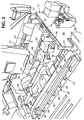
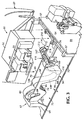
- the reference numeral 10 designates generally an automatic high speed mailing machine of the type in which the present invention is utilized, and comprises an elongate base, designated generally by the reference numeral 12, which supports a feed deck 14 that extends substantially the length of the base 12.
- a user interface having a control panel and a information display unit, designated generally by the reference numeral 20, is suitably mounted on the mailing machine base 12 in the vicinity of a cover 18 so as to be conveniently accessible to an operator.
- the cover 18 encloses a suitable separating mechanism for withdrawing the bottom envelope of a stack and feeding it into the feeding mechanism that conveys it past the ink jet printing device further described below and provides jam access.
- Another cover designated generally by the reference numeral 22, encloses most of the operating components of the mailing machine 10, including the tape storing and feeding mechanism described below, and can be raised to the dotted line position to afford an operator full access to the interior of the mailing machine 10.
- a weighing scale (not shown) is suitably integrated into the feed deck 14 for weighing mail pieces as they move along the feed deck so as to automatically set the postage meter to cause the printing device further described below to print an appropriate amount of postage.
- a postage meter (not shown) is detachably mounted to a meter pocket 15 located underneath the cover 22.
- the pocket 15 is suitable mounted to the base 12 to be repositionable so as to allow access to the meter.
- a plurality of nudger rollers 24 are mounted beneath the infeed end of the feed deck 14 and project upwardly trough suitable openings in the feed deck 14 for the purpose of separating the bottom envelope from a stack off envelopes placed on top of the nudger rollers 24, the stack being confined by suitable rear and end walls 26 and 28 respectively.
- the nudger rollers 24 feed the bottom most envelope to a separating device (not shown) located beneath the cover 18, which ensures that only one envelope at a time is fed into the mailing machine 10. From the separating device, the envelopes are fed through a flap closing and sealing device (not shown) which is also located beneath the cover 18 which closes and seals the flaps to the rear panels of the envelopes.
- the envelope conveyor 30 includes an endless belt 34 which extends around suitable drive rollers 36 suitably mounted on the mailing machine base 12, and a tensioning roller 38 to maintain proper tension on the belt 34.
- the belt 34 includes a lower run 40, and a plurality of back up pressure roller assemblies, designated generally by the reference numeral 42, are suitably mounted on the base unit 12 beneath the lower run 40 of the belt 34, each roller assembly 42 having a spring loaded arm 44 pivotally mounted on the base unit 12 and carrying a back up pressure roller 46 adjacent the free end of the arm 44.
- the plurality of back up rollers 46 maintain an envelope in firm driving engagement with the lower surface of the lower run 40 of the belt 34. Since the conveyor assembly 30 forms no part of the present invention, further description thereof is not deemed necessary for a full understanding of the present invention.
- the ink jet printing assembly 32 is mounted in the mailing machine base 12 generally in a location toward the downstream end of the envelope conveyor 30 and spaced therefrom toward the rear portion of the mailing machine 10.
- the printing assembly 32 includes at least one but preferably a pair of digital ink jet print heads 48 and 50, which are suitably mounted on a housing 52.
- the housing 52 is suitably mounted on a frame 54 which in turn is mounted for lateral movement within the mailing machine base 12 between an intermediate position and two extreme positions, the printing assembly 32 being shown in Fig. 2 in the intermediate position.
- the frame is moved between the three positions by a threaded rod 56 suitably mounted on a standing portion 57 of the mailing machine base 12.
- the rod 56 when rotated in the opposite direction, cause the frame 54, housing 52 and print heads 48 and 50 to move forwardly or rearwardly within the frame 12 from the intermediate position shown in Fig. 2.
- the intermediate position is a stand-by or maintenance position in which the print head(s) of any ink jet printer is maintained when the printer is not in operation.
- the print heads 48 and 50 are moved to a position overlying a guide plate 58 having a pair of apertures 60 through which the print heads 48 and 50 direct the ink from the nozzles on the lower end of the print heads 48 and 50 onto the surface of an envelope being conveyed past the location of the guide plate 58 by the conveyor assembly 30.
- the tape storing and feeding mechanism comprises an elongated tape storing means, designated generally by the reference numeral 62, which, as best seen in Fig. 2, is located generally rearwardly of the upstream end of the envelope conveyor 30.
- the tape storing means 62 is preferably formed as a one-piece, molded plastic receptacle having a rear supporting section 64, and a pair of upstanding side walls 66 and 68 which define an upper open trough 70 which extends the full length of the tape storing means 62.
- the storing means 62 is suitably removably secured to a plate 71 which is part of the base 12 of the mailing machine 10.
- the storing means 62 includes an upstream well, designated generally by the reference numeral 72, which is defined by an upstream end wall 74, upstream portions of the side walls 66 and 68, an upstream bottom wall 76 which slants downwardly at a shallow angle from left to right as viewed in Figs. 3 and 11, and a first intermediate wall 78 which slants sharply upwardly in the same direction.
- the upstream well 72 is adapted to hold a roll 80 of tape of indefinite length which is wound on a suitable spindle 82 which is easily manually accessible through the slots 84 in the upstream portions of the side walls 66 and 68 formed in the central portion of the upstream well 72.
- the first intermediate wall 78 is integrally connected to the bottom wall 76, but is free standing from that point on, in that the forward wall 78, as best seen in Fig. 12, is formed as a pair of wall portions 86 forming an elongate aperture 88 therebetween, and which join together adjacent the upper end of the first intermediate wall 78 in a solid portion 90 which has a curved upper edge 92. As best seen in Fig.
- the upper edge 92 of the first intermediate wall 78 is not connected to the side walls 66 and 68, as is the bottom portion, with the result that the upper edge 92 is free to move back and forth a limited distance due solely to the resilience of the plastic material from which the tape storing device 66 is formed.
- Wall 78 thus forms an elongated resilient element which absorbs the initial shock as the tape is accelerated, reducing the possibility that the tape might break.
- the tape storing device 62 further includes a downwstream well, designated generally by the reference numeral 94, which is defined by a second intermediate wall 96, a bottom wall 98 and a downstream end wall 100 which terminates upwardly in a forwardly curved lip 102, which constitutes a forward supporting means device 62, again, all for a purpose to be made clear hereinbelow.
- a downwstream well designated generally by the reference numeral 94, which is defined by a second intermediate wall 96, a bottom wall 98 and a downstream end wall 100 which terminates upwardly in a forwardly curved lip 102, which constitutes a forward supporting means device 62, again, all for a purpose to be made clear hereinbelow.
- the portion 108 then joins with a downwardly projecting reverse loop portion 110 which joins with an upwardly extending portion 112, the upper end of which is closely adjacent to the upper lip 102 of the downstream end wall 100 of the well 94.
- a further portion of the tape, as well as the functions of the previously described portions, will be further described hereinbelow.
- an elongated tape feeding and supporting means extends from the upper forwardly curved lip 102 of the tape storage device 62 to the forward wall 57 of the mailing machine base 12 for the purpose of feeding a discrete length of tape from the roll 80 thereof and supporting it beneath the print heads 48 and 50 of the printing device 32 in a manner now to be described.
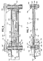
- the tape feeding and supporting means 114 comprises essentially three major parts, a tape supporting bridge, designated generally by the reference numeral 116, an upstream and downstream tape feeding mechanism, designated generally 118 and 120 respectively, and a cover device, designated generally by the reference numeral 122, for supporting the bridge 116.
- the supporting bridge 116 is the structure by which the tape is supported during the printing operation and therefore which must maintain the proper gap between the upper surface of the tape and the ink jet nozzles.
- the supporting bridge 116 is accomplished by molding the supporting bridge 116 from a plastic composition that is essentially a glass and carbon filled nylon material which provides a high degree of rigidity, dimensional control, static dissipation, resistance to warping and a smooth, virtually friction free surface on which the tape moves, and is also resistant to inks.
- the supporting bridge 116 has a lip 124 which is upwardly curved in the direction of feed of the tape and which is adapted to fit over the upper forwardly curved lip 102 of the downstream wall 100 of the tape storage means 62, the lip 124 also having a lateral dimension that is slightly less than that of the side walls 66 and 68 so as to fit therebetween and rest on the upper lip 102.
- the tape will slide very easily over the transition from the lip 102 on the wall 100 to the lip 124 on the bridge 116.
- the bridge 116 then has a relatively short infeed ramp portion 126 that is slightly inclined in the direction of feed, and a pair of side walls 128 and 130 which are spaced apart a distance substantially equal to the width of the tape, leaving just enough clearance so that the tape can pass freely between the walls 128 and 130.
- the walls 128 and 130 assist with aligning the tape when tape reloading is necessary
- the ramp portion 126 merges adjacent the upstream feeding mechanism 118 with a relatively long tape supporting portion 132 which extends from the location of merger to the upstanding wall 57 of the mailing machine base 12, to which the downstream end of the supporting portion 132 adjacent the downstream feeding mechanism 120, is suitably secured as by the locating pin 134.
- the bridge 116 is also provided with a pair of apertures 136 (Fig. 7) on a depending portion of the bridge 112 beneath the ramp 126 through which pins pass to connect the upstream end of the bridge 116 to a portion of the mailing machine base 112.
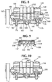
- the bridge 116 is formed as a continuous flat strip 136 which has integrally molded downwardly and upwardly projecting side edges 137 and 138 respectively (Fig. 9), thereby forming in cross section a laterally elongated "H" configuration.
- the bridge 116 also has a plurality of depending and upstanding ribs 140 and 142 respectively molded integrally with the upper and lower surfaces of the strip 136 (Figs. 7 and 9).
- the depending ribs 138 extend substantially the full length of the bridge 116, while the upstanding ribs 140 are discontinuous and have a unique configuration as further described below.
- One function of the ribs 138 and 140 is to prevent warping during the molding process, since it is known that when molding a flat piece with ribs formed on one side, the flat piece tends to warp slightly and bow due to unsymmetrical cooling which occurs during the molding process, which, in the case of the bridge 116, would cause the gap between the printing surface of the tape and the plane of the jet nozzles to vary across the printing area, resulting in an indicia of unacceptable print quality.
- the other function is to lend sufficient strength and rigidity to the bridge 116 to prevent any possibility that it can warp or otherwise change shape through prolonged use or damage from mishandling during the life of the mailing machine 10.
- the upstanding ribs 140 are of different lengths and are positioned in different locations on the upper surface of the flat strip 136.
- a first group of ribs, labeled 140a, 140b, 140c and 140d commence substantially at the juncture of the infeed ramp 126 and the flat strip 132, just on the downstream side of the feeding mechanism 118.
- the upstream ends of these ribs are depressed below the nip of the feed rollers 142 and 144 of the upstream feed mechanism 118 to ensure that the lead edge of the tape will feed smoothly onto the ribs.
- the rib 140a extends in the downstream direction of tape feed for a major portion of the length of the tape supporting portion 136
- the rib 140b extends in the same direction for only a minor portion of the length of the supporting portion 136
- the rib 140c extends for a slightly less distance than the rib 140b
- the rib 140d is a very short rib disposed adjacent the lower feed roller 162 and terminates at an aperture 232 formed in the bottom wall of the tape supporting portion, below which a suitable tape edge detection device, designated generally by the reference numeral 234 which detects the arrival of the leading edge of the tape at the location of the aperture 232 for a purpose to be fully explained below.
- the upstream tape feeding mechanism 118 is seen to comprise an upper roller assembly designated generally by the reference numeral 150 which comprises a roller having a plurality of large diameter segments 152 separated by smaller diameter segments 154, the roller being mounted on an upper shaft 156.
- the feeding mechanism 118 also includes a lower roller assembly designated generally by the reference numeral 160, which also comprises a roller having a plurality of large diameter segments 162 separated by smaller diameter segments 164 which are located in a complimentary manner to the large and small diameter segments 152 and 154 of the upper roller assembly 118.
- the lower roller is mounted on a lower shaft 166, on one end of which is mounted a pulley 167. As best seen in Fig.
- the upper shaft 156 is journaled for rotation in the upper ends of a pair of elongated bearing blocks 168 which are mounted for limited vertical movement in a pair of suitable bearing housings 170 formed integrally with the upstream end of the tape support bridge 116 on both sides thereof.
- the lower shaft 166 is journaled for rotation in a pair of bearing plates 172 (Fig. 5) which are suitably secured to the bearing housings 170 as by the screws 174.
- Each of the bearing blocks 168 project downwardly sufficiently far to terminate in bifurcated projections 176 which extend beyond the bottom surface 179 of a portion of the support bridge 116 which extends between the bearing housings 170, and an elongated plate 180 extends across the width of the bearing housings 170 and is mounted on the bifurcated projections 176 of the bearing blocks 168 by means of apertures 182 formed adjacent each end of the elongated plate 180 and which are of smaller diameter than the projections 176, but which engage with an annular slot 184 formed in each projection 176 by compressing the legs of the bifurcated projections when the plate 180 is pressed over the projections 176.
- a downwardly extending center stud 188 is formed integrally with the bottom surface 178 and is received in a center aperture 190 formed in the elongated plate 180.
- a compression spring 192 is captured around the stud 188 between the upper surface of the elongated plate 180 and the bottom surface 178 of the portion of the support bridge 116 that extends between the bearing housings 170 so as to exert a downward force on the upper shaft 156, thereby pressing the large diameter segments 152 of the upper roller into firm engagement with the corresponding segments 162 of the lower rollers so as to exert a firm driving engagement with the tape therebetween, as best seen in Fig. 8.
- the bearing blocks 168 are provided with elongated slots 194 to provide for the limited movement thereof.
- the downstream roller assembly 120 is identical to that of the upstream roller assembly with the exceptions now described.
- the upper roller assembly designated generally by the reference numeral 196 still comprises an upper shaft 198, but in this assembly the upper roller has only two large diameter segments 200 with an elongated smaller diameter segment 202 extending therebetween, with the result that the tape is engaged only between the large diameter segments 200 of the upper roller and the corresponding outermost larger diameter segments 204 of the lower roller.
- the lower shaft 206 for the lower roller has a pulley 208 mounted on the end thereof that corresponds to the end of the lower shaft 176 which carries the pulley 167, and a timing belt 210 extends between the pulleys 176 and 208 so that the shafts 166 and 206 are driven in synchronism at the same velocity.
- a second pulley 212 is mounted on the lower shaft 166 of the lower roller assembly 160, and a drive belt 214 is connected between this pulley and a suitable motor mounted in the base 12 of the mailing machine, with the result that the shaft 166 is the main drive shaft for both the upstream and downstream tape feeding mechanisms 118 and 120.
- a knife edge roller (not shown) having a narrow contact surface is positioned between rollers 200 so as to bear upon an unprinted portion of the tape in order to prevent the tape from bowing upwards and coming into contact with cover 220 after the indicia is printed and while the ink is still wet, as well as to guide entrance into downstream paths (not shown).
- the cover device 122 which extends over the top of the tape supporting bridge 116 is seen to comprise an elongated strip of sheet metal 220 which extends substantially from the nip of the rollers in the upstream and downstream tape feeding mechanisms 118 and 120, and is adapted to lie on the upper surface of the upwardly projecting side edges 138.
- a pair of side edges 222 extend downwardly and terminate in short laterally outwardly angled flanges 224.
- the cover device 122 is removably retained in place on the supporting bridge 116 by means of a plurality of projections (not shown) which are engaged by the detents 226 formed on the side edges 222 of the cover device 122.
- the cover device 122 is provided with an elongated aperture designated generally by the reference number 230 in Figs. 4 and 6.
- Figs. 13 through 17 show a schematic representation of the operation of the tape feeding and supporting mechanism of the subject invention.
- tape from roll 80 is held substantially tautly above well 94 by upstream feeding mechanism 118.
- Detector 252 and light source 254 detect the leading edge of the tape to synchronize operation of the tape storing end feeding mechanism of the invention with operation of print heads 48 and 50.
- feeding mechanism 118 advances the tape past print heads 48 and 50, which print an indicia, until the tape is engaged by downstream feeding mechanism 120 which continues to advance the tape until it is severed by conventional severing mechanism 250.
- the tape storing and feeding mechanism reverses and withdraws the tape to the initial position, forming a loop in well 94.
- the tape storing and feeding mechanism reverses and withdraws the tape to the initial position, forming a loop in well 94.
- feeder mechanism 118 again advances the tape for printing, and in Fig. 17 the indicia is printed and the tape advanced by feeder mechanism 120 and the cycle repeats.
Landscapes
- Physics & Mathematics (AREA)
- General Physics & Mathematics (AREA)
- Engineering & Computer Science (AREA)
- Computer Security & Cryptography (AREA)
- Handling Of Continuous Sheets Of Paper (AREA)
- Advancing Webs (AREA)
Applications Claiming Priority (2)
| Application Number | Priority Date | Filing Date | Title |
|---|---|---|---|
| US09/073,534 US6224280B1 (en) | 1998-05-06 | 1998-05-06 | Tape storing and feeding mechanism for mailing machines |
| US73534 | 1998-05-06 |
Publications (2)
| Publication Number | Publication Date |
|---|---|
| EP0961235A2 true EP0961235A2 (de) | 1999-12-01 |
| EP0961235A3 EP0961235A3 (de) | 2000-11-15 |
Family
ID=22114264
Family Applications (1)
| Application Number | Title | Priority Date | Filing Date |
|---|---|---|---|
| EP99108574A Withdrawn EP0961235A3 (de) | 1998-05-06 | 1999-05-06 | Bandpeicher- und Zuführmechanismus für Frankiermaschinen |
Country Status (3)
| Country | Link |
|---|---|
| US (2) | US6224280B1 (de) |
| EP (1) | EP0961235A3 (de) |
| CA (1) | CA2271081C (de) |
Cited By (5)
| Publication number | Priority date | Publication date | Assignee | Title |
|---|---|---|---|---|
| WO2001062506A1 (de) * | 2000-02-23 | 2001-08-30 | Frama Ag | Frankiermaschine |
| EP1193655A1 (de) * | 2000-09-29 | 2002-04-03 | Neopost Industrie | Mehrzweckfrankiermaschine |
| FR2817837A1 (fr) * | 2000-12-13 | 2002-06-14 | Neopost Ind | Distributeur d'etiquettes en bande |
| US6659579B2 (en) | 2000-12-13 | 2003-12-09 | Neopost Industrie | System for controlling the ink level in franking machine |
| EP1431924A3 (de) * | 2002-12-19 | 2006-06-07 | Pitney Bowes Inc. | Verfahren und System zur automatischen Generierung von Postwertzeichen in einem Postsendung verarbeitenden System |
Families Citing this family (9)
| Publication number | Priority date | Publication date | Assignee | Title |
|---|---|---|---|---|
| US6619305B1 (en) * | 2000-01-11 | 2003-09-16 | Seagate Technology Llc | Apparatus for single disc ultrasonic cleaning |
| USD464992S1 (en) | 2002-03-12 | 2002-10-29 | Pitney Bowes Inc. | Mailing machine |
| USD464991S1 (en) | 2002-03-12 | 2002-10-29 | Pitney Bowes Inc. | Mailing machine |
| USD488501S1 (en) | 2002-11-22 | 2004-04-13 | Pitney Bowes Inc. | Mailing machine |
| USD494615S1 (en) | 2003-09-30 | 2004-08-17 | Pitney Bowes Inc. | Mailing machine |
| USD520052S1 (en) | 2004-06-30 | 2006-05-02 | Pitney Bowes Inc. | Mailing machine |
| DE102007046855A1 (de) * | 2007-09-28 | 2009-04-02 | Böwe Bell & Howell GmbH | Briefbearbeitungsvorrichtung mit Drucker |
| US9079432B2 (en) * | 2012-09-28 | 2015-07-14 | Canon Kabushiki Kaisha | Sheet conveying device with sheet edge guide downstream of buffer unit |
| IT201900018722A1 (it) * | 2019-10-14 | 2021-04-14 | Ms Printing Solutions S R L | Dispositivo e procedimento di trattamento di materiale in foglio, impianto e procedimento di stampa di materiale in foglio |
Family Cites Families (33)
| Publication number | Priority date | Publication date | Assignee | Title |
|---|---|---|---|---|
| US2332152A (en) | 1943-10-19 | Web feeding device | ||
| US1958355A (en) | 1934-05-08 | Attachment for postage meter | ||
| US2533317A (en) | 1950-12-12 | Tape control device | ||
| US3401630A (en) | 1964-11-12 | 1968-09-17 | Pitney Bowes Inc | Record material feeding means |
| US3427968A (en) | 1966-06-10 | 1969-02-18 | Friden Inc | Postage meter tape feeding mechanism |
| US3664597A (en) | 1970-05-11 | 1972-05-23 | Singer Co | Braking device for a tape dispenser |
| US3712527A (en) | 1970-08-24 | 1973-01-23 | Pitney Bowes Inc | Method and apparatus for handling tape |
| US3749013A (en) | 1971-05-17 | 1973-07-31 | Better Packages Inc | Strip material dispenser feed-out control |
| DE2219270C3 (de) | 1972-04-20 | 1975-05-22 | Francotyp Gmbh, 1000 Berlin | Frankiermaschine mit einer Brief- und einer Streifenzuführungsvorrichtung |
| US4478143A (en) * | 1979-02-05 | 1984-10-23 | Mannesmann Aktiengesellschaft | Printer |
| JPS571150A (en) | 1980-05-30 | 1982-01-06 | Koyo Jidoki | High speed feeder |
| US4568950A (en) | 1984-06-19 | 1986-02-04 | Pitney Bowes Inc. | Postage meter-thermal tape pressure and drive control printer |
| US5041845A (en) * | 1987-10-13 | 1991-08-20 | Canon Kabushiki Kaisha | Heat transfer recording apparatus with a common drive source for selective plural functions |
| US4957179A (en) | 1987-12-17 | 1990-09-18 | Pitney Bowes Inc. | Tape module for a modular mailing machine |
| US4877197A (en) * | 1988-07-22 | 1989-10-31 | Invivo Research, Inc. | Instrument housing with improved paper feed |
| US4922085A (en) | 1988-12-28 | 1990-05-01 | Pitney Bowes Inc. | Mailing machine tape module and tape drive thereof |
| US5174824A (en) | 1990-10-31 | 1992-12-29 | Pitney Bowes Inc. | Tape take-away and moistening system |
| EP0531992B1 (de) * | 1991-09-13 | 1998-06-03 | Canon Kabushiki Kaisha | Aufzeichnungsblätterstapel mit darin verteilten Reinigungsblättern und ein Verfahren zur Wartung des Aufzeichnungsgerätes |
| US5175518A (en) * | 1991-10-15 | 1992-12-29 | Watkins-Johnson Company | Wide percentage bandwidth microwave filter network and method of manufacturing same |
| CH685693A5 (de) | 1992-03-10 | 1995-09-15 | Frama Ag | Vorrichtung zum Etikettentransport. |
| MY108892A (en) * | 1992-07-14 | 1996-11-30 | Nec Corp | Paper cutting device using a movable cutting wheel |
| US5378070A (en) | 1993-02-08 | 1995-01-03 | Pitney Bowes Inc. | Tape positioning apparatus for mailing machine |
| JP2570886Y2 (ja) * | 1993-04-05 | 1998-05-13 | キヤノンアプテックス株式会社 | タックラベルロール |
| JPH06340166A (ja) * | 1993-04-06 | 1994-12-13 | Canon Inc | インクジェット用被記録材、この製造方法及びこれに記録するインクジェット記録装置 |
| US5392703A (en) * | 1994-01-11 | 1995-02-28 | Pitney Bowes Inc. | Tape feeding, cutting and ejecting apparatus for a mailing machine |
| JPH07214835A (ja) * | 1994-01-31 | 1995-08-15 | New Oji Paper Co Ltd | プリンタ |
| US5415484A (en) * | 1994-02-28 | 1995-05-16 | Pitney Bowes Inc. | Method and apparatus for cutting mailing machine roll tape |
| JPH082754A (ja) * | 1994-06-22 | 1996-01-09 | Matsushita Graphic Commun Syst Inc | インクジェット記録装置 |
| JP3432052B2 (ja) * | 1994-09-02 | 2003-07-28 | キヤノン株式会社 | インクジェット記録装置 |
| US5467709A (en) * | 1994-12-22 | 1995-11-21 | Pitney Bowes Inc. | Mailing machine utilizing ink jet printer |
| JPH091883A (ja) * | 1995-06-16 | 1997-01-07 | Nec Eng Ltd | インクジェット式記録機構 |
| JP3841315B2 (ja) * | 1995-12-26 | 2006-11-01 | キヤノン株式会社 | プリント装置およびこの装置に用いられるプリント方法 |
| US6118462A (en) * | 1997-07-01 | 2000-09-12 | Memtrax Llc | Computer system controller having internal memory and external memory control |
-
1998
- 1998-05-06 US US09/073,534 patent/US6224280B1/en not_active Expired - Fee Related
-
1999
- 1999-05-05 CA CA002271081A patent/CA2271081C/en not_active Expired - Fee Related
- 1999-05-06 EP EP99108574A patent/EP0961235A3/de not_active Withdrawn
-
2000
- 2000-04-21 US US09/645,979 patent/US6309119B1/en not_active Expired - Lifetime
Cited By (10)
| Publication number | Priority date | Publication date | Assignee | Title |
|---|---|---|---|---|
| WO2001062506A1 (de) * | 2000-02-23 | 2001-08-30 | Frama Ag | Frankiermaschine |
| US7255422B2 (en) | 2000-02-23 | 2007-08-14 | Frama Ag | Franking machine |
| EP1193655A1 (de) * | 2000-09-29 | 2002-04-03 | Neopost Industrie | Mehrzweckfrankiermaschine |
| FR2814839A1 (fr) * | 2000-09-29 | 2002-04-05 | Neopost Ind | Machine a affranchir polyvalente |
| US6579021B2 (en) | 2000-09-29 | 2003-06-17 | Neopost Industrie | Polyvalent franking machine |
| FR2817837A1 (fr) * | 2000-12-13 | 2002-06-14 | Neopost Ind | Distributeur d'etiquettes en bande |
| EP1215631A1 (de) * | 2000-12-13 | 2002-06-19 | Neopost Industrie | Spender für bahnförmige Etiketten |
| US6659579B2 (en) | 2000-12-13 | 2003-12-09 | Neopost Industrie | System for controlling the ink level in franking machine |
| US6764235B2 (en) | 2000-12-13 | 2004-07-20 | Neopost Industrie | Label dispenser for franking machine |
| EP1431924A3 (de) * | 2002-12-19 | 2006-06-07 | Pitney Bowes Inc. | Verfahren und System zur automatischen Generierung von Postwertzeichen in einem Postsendung verarbeitenden System |
Also Published As
| Publication number | Publication date |
|---|---|
| EP0961235A3 (de) | 2000-11-15 |
| CA2271081A1 (en) | 1999-11-06 |
| CA2271081C (en) | 2008-01-29 |
| US6309119B1 (en) | 2001-10-30 |
| US6224280B1 (en) | 2001-05-01 |
Similar Documents
| Publication | Publication Date | Title |
|---|---|---|
| US6309119B1 (en) | Tape storing and feeding mechanism for mailing machines | |
| CA2341628C (en) | Ticket dispensing mechanism | |
| US5813326A (en) | Mailing machine utilizing ink jet printer | |
| US5467709A (en) | Mailing machine utilizing ink jet printer | |
| USRE38926E1 (en) | Printer including an ink cartridge | |
| USRE38092E1 (en) | Image forming apparatus | |
| US5959652A (en) | Thermal ink ribbon cassette for mailing machines | |
| US6652173B1 (en) | Ticket dispensing mechanism | |
| US5800076A (en) | Printer having guide plate extending to printhead | |
| US5988903A (en) | Printer for printing on single sheets and an endless paper strip | |
| US7810810B2 (en) | Apparatus for pressing flat materials onto a transport module | |
| US4668960A (en) | Recording apparatus with dual-purpose guide | |
| EP0662671B1 (de) | Frankiermaschine mit einer Einrichtung zum Zuführen und Schneiden eines Bandes | |
| US5415484A (en) | Method and apparatus for cutting mailing machine roll tape | |
| JP2004114363A (ja) | インクジェット画像形成装置 | |
| US5794223A (en) | Method for control of length of imprint for a mailing machine | |
| US6206500B1 (en) | Printer having a guide plate for transporting waste ink | |
| US5460362A (en) | Mailing machine including modifiable mailpiece drive | |
| JP3553980B2 (ja) | プリンタ | |
| JP2517763Y2 (ja) | プリンタ | |
| JPH05330532A (ja) | ラベル剥離装置 | |
| US5452214A (en) | Method for initializing a tape feeding, cutting and ejection apparatus for a mailing machine | |
| JPH0413177Y2 (de) | ||
| JP2551875Y2 (ja) | 排紙案内装置 | |
| JPH11139665A (ja) | 排紙仕分け装置 |
Legal Events
| Date | Code | Title | Description |
|---|---|---|---|
| PUAI | Public reference made under article 153(3) epc to a published international application that has entered the european phase |
Free format text: ORIGINAL CODE: 0009012 |
|
| AK | Designated contracting states |
Kind code of ref document: A2 Designated state(s): DE FR GB |
|
| AX | Request for extension of the european patent |
Free format text: AL;LT;LV;MK;RO;SI |
|
| PUAL | Search report despatched |
Free format text: ORIGINAL CODE: 0009013 |
|
| AK | Designated contracting states |
Kind code of ref document: A3 Designated state(s): AT BE CH CY DE DK ES FI FR GB GR IE IT LI LU MC NL PT SE |
|
| AX | Request for extension of the european patent |
Free format text: AL;LT;LV;MK;RO;SI |
|
| RIC1 | Information provided on ipc code assigned before grant |
Free format text: 7G 07B 17/00 A, 7B 41J 15/04 B, 7B 41J 11/06 B |
|
| 17P | Request for examination filed |
Effective date: 20010509 |
|
| AKX | Designation fees paid |
Free format text: DE FR GB |
|
| 17Q | First examination report despatched |
Effective date: 20061212 |
|
| STAA | Information on the status of an ep patent application or granted ep patent |
Free format text: STATUS: THE APPLICATION IS DEEMED TO BE WITHDRAWN |
|
| 18D | Application deemed to be withdrawn |
Effective date: 20101201 |