EP0961236A2 - Vorrichtung zum Bedrucken von Postgut - Google Patents
Vorrichtung zum Bedrucken von Postgut Download PDFInfo
- Publication number
- EP0961236A2 EP0961236A2 EP99250147A EP99250147A EP0961236A2 EP 0961236 A2 EP0961236 A2 EP 0961236A2 EP 99250147 A EP99250147 A EP 99250147A EP 99250147 A EP99250147 A EP 99250147A EP 0961236 A2 EP0961236 A2 EP 0961236A2
- Authority
- EP
- European Patent Office
- Prior art keywords
- guide wall
- printing
- wall
- opening
- contact area
- Prior art date
- Legal status (The legal status is an assumption and is not a legal conclusion. Google has not performed a legal analysis and makes no representation as to the accuracy of the status listed.)
- Granted
Links
- 238000012545 processing Methods 0.000 claims description 11
- 238000009434 installation Methods 0.000 claims 3
- 238000002508 contact lithography Methods 0.000 claims 1
- 238000000034 method Methods 0.000 description 3
- 230000033228 biological regulation Effects 0.000 description 2
- 230000007704 transition Effects 0.000 description 2
- 230000006835 compression Effects 0.000 description 1
- 238000007906 compression Methods 0.000 description 1
- 238000000151 deposition Methods 0.000 description 1
- 230000002349 favourable effect Effects 0.000 description 1
- 230000014759 maintenance of location Effects 0.000 description 1
- 238000012805 post-processing Methods 0.000 description 1
- 230000000452 restraining effect Effects 0.000 description 1
Images




Classifications
-
- G—PHYSICS
- G07—CHECKING-DEVICES
- G07B—TICKET-ISSUING APPARATUS; FARE-REGISTERING APPARATUS; FRANKING APPARATUS
- G07B17/00—Franking apparatus
- G07B17/00459—Details relating to mailpieces in a franking system
- G07B17/00508—Printing or attaching on mailpieces
-
- B—PERFORMING OPERATIONS; TRANSPORTING
- B41—PRINTING; LINING MACHINES; TYPEWRITERS; STAMPS
- B41J—TYPEWRITERS; SELECTIVE PRINTING MECHANISMS, i.e. MECHANISMS PRINTING OTHERWISE THAN FROM A FORME; CORRECTION OF TYPOGRAPHICAL ERRORS
- B41J13/00—Devices or arrangements of selective printing mechanisms, e.g. ink-jet printers or thermal printers, specially adapted for supporting or handling copy material in short lengths, e.g. sheets
- B41J13/10—Sheet holders, retainers, movable guides, or stationary guides
- B41J13/12—Sheet holders, retainers, movable guides, or stationary guides specially adapted for small cards, envelopes, or the like, e.g. credit cards, cut visiting cards
-
- B—PERFORMING OPERATIONS; TRANSPORTING
- B41—PRINTING; LINING MACHINES; TYPEWRITERS; STAMPS
- B41L—APPARATUS OR DEVICES FOR MANIFOLDING, DUPLICATING OR PRINTING FOR OFFICE OR OTHER COMMERCIAL PURPOSES; ADDRESSING MACHINES OR LIKE SERIES-PRINTING MACHINES
- B41L45/00—Kinds or types of addressing machines or of like series-printing machines
- B41L45/02—Kinds or types of addressing machines or of like series-printing machines using printing plates
- B41L45/06—Kinds or types of addressing machines or of like series-printing machines using printing plates for addressing combined with other operations, e.g. franking, collating documents
-
- G—PHYSICS
- G07—CHECKING-DEVICES
- G07B—TICKET-ISSUING APPARATUS; FARE-REGISTERING APPARATUS; FRANKING APPARATUS
- G07B17/00—Franking apparatus
- G07B17/00459—Details relating to mailpieces in a franking system
- G07B17/00467—Transporting mailpieces
-
- G—PHYSICS
- G07—CHECKING-DEVICES
- G07B—TICKET-ISSUING APPARATUS; FARE-REGISTERING APPARATUS; FRANKING APPARATUS
- G07B17/00—Franking apparatus
- G07B17/00185—Details internally of apparatus in a franking system, e.g. franking machine at customer or apparatus at post office
- G07B17/00193—Constructional details of apparatus in a franking system
- G07B2017/00233—Housing, e.g. lock or hardened casing
-
- G—PHYSICS
- G07—CHECKING-DEVICES
- G07B—TICKET-ISSUING APPARATUS; FARE-REGISTERING APPARATUS; FRANKING APPARATUS
- G07B17/00—Franking apparatus
- G07B17/00459—Details relating to mailpieces in a franking system
- G07B17/00508—Printing or attaching on mailpieces
- G07B2017/00516—Details of printing apparatus
- G07B2017/00524—Printheads
- G07B2017/00532—Inkjet
-
- G—PHYSICS
- G07—CHECKING-DEVICES
- G07B—TICKET-ISSUING APPARATUS; FARE-REGISTERING APPARATUS; FRANKING APPARATUS
- G07B17/00—Franking apparatus
- G07B17/00459—Details relating to mailpieces in a franking system
- G07B17/00508—Printing or attaching on mailpieces
- G07B2017/00572—Details of printed item
- G07B2017/00596—Printing of address
Definitions
- the invention relates to a device for printing mail, in particular a franking and / or addressing machine, which is provided with an ink printing device.
- Letter post processing systems usually consist of a letter separating device, a franking and / or addressing machine with optional scales and a storage device, see DE-M 96 09 167.3 in the design patent sheet of the German Patent Office dated May 24, 1997, part la, goods class 18/02.
- the letters are stacked, separated and, if necessary, sealed.
- the letters are either printed continuously and continuously with a rigidly arranged printing device, see DE 196 05 014 C1 and DE 196 45 303 C1, or intermittently with an adjustable printing device, see US Pat. No. 5,025,386.
- the latter also applies to slow-working franking machines in which the letters are created individually by hand, compare EP 0 782 096 A2 and WO 90/04824.
- All known franking machines see for example DE 40 20 578 A1, DE 195 08 180 A1, DE 196 05 015 C1 and US 5,025,386 common that the printing medium individually serial of the printing device be fed.
- the guide means - transport shaft, pressure rollers - In the area of the printing device are designed so that Print media up to a certain thickness can be processed. Most machines only allow letter thicknesses up to 5mm.
- the envelope flap of the envelope may be arranged upright.
- the purpose of the invention is to enlarge the area of application.
- the invention has for its object a device of the beginning mentioned type with which it is possible, on the one hand Letters of any thickness up to parcels and small packages Manual system to be printed immediately and on the other hand in stacks automatically create mixed mail of small thickness.
- the invention takes advantage of the previously completely neglected fact that the foremost letter of a stack, due to the flush contact with a lateral guide means and the parallel contact with another guide means, is already arranged as a single letter in relation to a printing device present in this so that this can be printed.
- the letters of a stack are first printed and then separated or transported away.
- the device can be used as a franking and / or addressing machine or as a label printer. The latter use applies if the mail is only provided with a label for the carrier.
- the franking machine is functionally divided into a system area I and a transport area II, both of which partially overlap in the transition area.
- the contact area is designed as an open corner, which is delimited by a rear, common guide wall 1, a lower guide wall 2 and a right, lateral guide wall 31.
- the mail item A is placed either in stacks or individually flush with the right guide wall 31 and with the front facing the rear guide wall 1, see also FIGS. 3 and 4.
- the lower guide wall 2 slopes slightly towards the rear guide wall 1, preferably by 18 degrees.
- the rear guide wall 1 is arranged orthogonally to the lower guide wall 2 and consequently inclined to the rear by the same angular amount. As a result of the inclination, letters assume a defined stable position without further support.
- the lower guide wall 2 has a groove 22 in which a pressure bracket 21 is slidably mounted on the rear guide wall 1 and away from it.
- the pressure bracket 21 is tensioned towards the rear guide wall 1 by means of a spring 23, see FIG. 2. In this way, a stack of letters is pressed against the rear guide wall 1 with approximately the same force.
- the raised pressure bracket 21 closes with the front wall 8 in its pulled-out end position. It is also conceivable to resiliently guide the pressure bracket 21 in two parallel grooves.
- spring design from a tension spring to a compression spring.
- the right guide wall 31 is - except for a negligible draft slope - essentially vertical and also orthogonal to the lower guide wall 2.
- the right guide wall 31 is also the left side wall of a housing part 3, which contains an operating keyboard 32 and a display 33.
- the operating mode "manual system” or “automatic letter processing” can also be set using the operating keyboard 32.
- the housing part 3 can be both firmly integrated into the overall device housing and also be a closed, attachable structural unit. The latter variant would offer favorable options for security measures for a meter section.
- a transport slot 7 is provided with a trigger device 6, which extends into the contact area I.
- the rear guide wall 1 has an opening 11 for a pressure device 4 and an opening 13 for a drive element 61 of the trigger device 6.
- the printing device 4 contains an ink print head 41 which is arranged adjustably within the opening 11.
- the opening 11 is such that the letters A standing on the edge of their envelope flap are provided with the franking imprint in the prescribed area. The same happens with parcels.
- the area is arranged in accordance with the applicable postal regulations. According to the currently applicable regulations of Deutsche Post, the lower edge of the franking imprint must maintain a predetermined distance of approximately 40 mm from the neighboring letter edge. With a permissible franking imprint width of one inch or 25.4 mm, the upper edge of the franking imprint therefore has a distance of around 14 mm from the adjacent letter edge. Accordingly, the lower edge of the opening 11 is a maximum of 14 mm above the level of the lower guide wall 2.
- Postage A is first created accordingly, then by the adjustable ink print head 41 printed and after the printing process either automatically by means of the trigger device 6 transported to the right and ejected or taken away by hand.
- the adjustable ink print head 41 printed and after the printing process either automatically by means of the trigger device 6 transported to the right and ejected or taken away by hand.
- the resulting nozzle row length of the ink printhead used 41 becomes the same during printing along the length the opening 11 only once or several times with different heights adjusted.
- FIG. 2 shows a franking and addressing machine with the pressure bracket 21 folded down and locked in this position.
- the pressure bracket 21 By folding down the pressure bracket 21 into the plane of the lower guide wall 2, the contact area for larger mail items A, such as parcels or small parcels, is released and the storage area is enlarged beyond the front wall 8, see also FIG. 4.
- a further opening 12 and a second adjustable ink print head 42 are provided in the rear guide wall for address printing.
- the processing speed would then be correspondingly lower. The execution is possible according to the wishes of the user.
- a single mail item A is created in the form of a package, this corresponds to the "manual system" mode. In this mode the trigger device 6 is switched off.
- mail item A is inserted in the form of a stack of letters between the pressure bracket 21 and the rear guide wall 1.
- This corresponds to the "automatic letter processing" operating mode, in which the withdrawal device 6 is activated.
- the franking machine can expediently be followed by a suitable depositing device.
- the desired operating mode is set using the control keyboard 32.
- FIG. 5 shows a franking machine for the optional processing of individual mail items A in the form of flat packages or small packages, see also FIG. 6, or in the form of letters stacked one above the other, see also FIG. 7.
- the franking machine is divided into a system area I and a transport area II, both of which partially overlap in the transition area.
- the contact area is designed as a compartment which is open on two sides and is delimited by a rear guide wall 1, a lower guide wall 2, an upper guide wall 9 and a right lateral guide wall 31, the guide walls 1, 2, 31 being approximately orthogonal to one another.
- the lower guide wall 2 is designed in the form of a height-adjustable plate.
- the rear guide wall 1 is provided with a vertical groove 14, in which the lower guide wall 2 is guided during the adjustment.
- An adjustment mechanism for guide wall 2 is provided behind the guide wall 1 in a manner that is not visible.
- the mail item A is placed either in stacks or individually flush on the right guide wall 31 and on the rear guide wall 1 and is directed with the front to the upper guide wall 9.
- the inner surfaces of the lower guide wall 2 and the upper guide wall 9 are arranged parallel to one another.
- the control keyboard 32 and the display 33 are housed in the top of the upper guide wall 9.
- the right guide wall 31 is the left side wall of a housing part 3, between the top wall 30 and the upper guide wall 9 parallel thereto, a transport slot 7 with a trigger device 6 is provided, which extends into the contact area I.
- the upper guide wall 9 has an opening 91 on the inside for a pressure device 4 and an opening 93 for a drive element 61 of the trigger device 6, which also includes retaining fingers 62 on the top of the top wall 30.
- the printing device 4 contains at least one ink print head 41 which is arranged to be adjustable within the opening 91.
- a sensor 43 is present in the upper guide wall 9, which is electrically coupled to the printing device 4.
- the mail item A is first created accordingly, then the lower guide wall 2 is raised in the direction of the upper guide wall 9 until the upper side of the mail item A lying over it positively touches the sensor 43 and triggers the printing device 4 via this and switches off the adjustment mechanism. After the printing process, the mail item A is either automatically drawn horizontally into the transport slot 7 by means of the take-off device 6, transported away in the latter and then ejected or removed by hand.
- the retention fingers 62 are intended to prevent two letters from being drawn off at the same time. This version can also be supplemented for address printing.
- FIG. 6 is a single mail item A in the form of a flat package created, corresponds to the operating mode "manual system". In this operating mode the trigger device is switched off via the control keyboard 32.
- Postgut A is in the form of a stack of letters between the lower guide plate 2 and the upper guide plate 9 inserted. This corresponds to the "automatic letter processing" mode in which the trigger device is switched on.
Landscapes
- Physics & Mathematics (AREA)
- General Physics & Mathematics (AREA)
- Engineering & Computer Science (AREA)
- Computer Security & Cryptography (AREA)
- Devices For Checking Fares Or Tickets At Control Points (AREA)
- Sorting Of Articles (AREA)
Abstract
Description
Üblicherweise bestehen Briefpostverarbeitungssysteme aus einer Briefvereinzelungsvorrichtung, einer Frankier- und/oder Adressiermaschine mit optionaler Waage und einer Ablagevorrichtung, vergleiche DE-M 96 09 167.3 in Geschmacksmusterblatt des Deutschen Patentamtes vom 24.05.1997, Teil la, Warenklasse 18/02..
In der Briefvereinzelungsvorrichtung werden die Briefe stapelweise angelegt, vereinzelt und bedarfsweise verschlossen.
In der Frankier- und/oder Adressiermaschine werden die Briefe entweder einzeln kontinuierlich durchlaufend mit einer starr angeordneten Druckeinrichtung, siehe DE 196 05 014 C1 und DE 196 45 303 C1, oder intermittierend mit einer verstellbaren Druckeinrichtung, vergleiche US 5,025,386, bedruckt. Letzteres trifft auch für langsam arbeitende Frankiermaschinen zu, bei denen die Briefe einzeln von Hand angelegt werden, vergleiche EP 0 782 096 A2 und WO 90/04824.
Die Briefe sind dabei zwischen einem federnd gelagerten Andruckbügel und mindestens einer Antriebswalze sowie einer leicht nach hinten geneigten Führungsplatte angeordnet. Die Standfläche für die Briefe und die Führungsplatte sind zueinander orthogonal. Durch die Neigung der Führungsplatte wird eine stabile Vorzugslage des Briefstapels erreicht. Mittels der Antriebswalze werden die Briefe seitlich weggeschoben.
Die Erfindung nutzt den bisher völlig unbeachteten Sachverhalt aus, daß der vorderste Brief eines Stapels auf Grund der bündigen Anlage an einem seitlichen Führungsmittel und der parallelen Anlage an einem weiteren Führungsmittel gegenüber einer in dieser vorhandenen Druckeinrichtung bereits wie ein einzelner Brief so definiert angeordnet ist, daß dieser bedruckt werden kann.
Im Unterschied zur bisherigen, allgemein praktizierten Verfahrensweise werden erfindungsgemäß die Briefe eines Stapels erst bedruckt und dann vereinzelt beziehungsweise abtransportiert. Dadurch kann die gesamte Brieferfassung beziehungsweise Abtastung und Drucksteuerung wesentlich vereinfacht werden.
Die Vorrichtung ist als Frankier- und/oder Adressiermaschine oder als Labeldrucker verwendbar. Letzterer Einsatz trifft zu , wenn das Postgut nur mit einer Kennzeichnung für den Carier versehen wird.
Gegenüber einer reinen Handanlage-Frankiermaschine wird bei automatischer Stapelverarbeitung eine wesentliche Steigerung der Verarbeitungsgeschwindigkeit erreicht.
Darüber hinaus können auf Grund der Ausführung des Anlagebereiches für das Postgut als größerer Raum auch Briefe über der üblichen Normdicke und sogar kleine Pakete beziehungsweise Päckchen bedruckt werden, wenn diese von Hand angelegt werden oder noch in den Bereich der maximalen Stapellänge passen. Damit wird die Druckeinrichtung effektiver als bisher benutzt und es kann auf zusätzliche Streifengebermagazine oder aufwendige Streifenaufbringungen verzichtet werden. Der automatische Abtransport bleibt hierbei abgeschaltet.
- Fig. 1
- Eine perspektivische Ansicht einer erfindungsgemäßen Frankiermaschine zur Verarbeitung von auf einer Kante stehend angeordneten Briefen oder von einzelnen Paketen von vorn oben links,
- Fig. 2
- eine perspektivische Ansicht einer erfindungsgemäßen Frankier- und Adressiermaschine für Postgut analog zu Fig. 1,
- Fig. 3
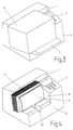
- eine Ansicht zu Fig. 2 mit aufgelegtem Paket,
- Fig. 4
- eine Ansicht zu Fig. 1 mit eingelegtem Briefstapel,
- Fig. 5
- eine perspektivische Ansicht einer erfindungsgemäßen Frankiermaschine zur Verarbeitung von liegend angeordneten Briefen oder von einzelnen Paketen von vorn unten links,
- Fig. 6
- eine Ansicht zu einer Frankiermaschine gemäß Fig. 5 mit eingelegtem Paket von vorn oben links,
- Fig. 7
- eine Ansicht zu Fig. 6 mit eingelegtem Briefstapel.
Der Anlagebereich list als offene Ecke gestaltet, die durch eine hintere, gemeinsame Führungswand 1, ein untere Führungswand 2 und eine rechte, seitliche Führungswand 31 begrenzt wird.
Das Postgut A wird entweder stapelweise oder einzeln bündig an die rechte Führungswand 31 und mit der Frontseite zur hinteren Führungswand 1 gerichtet angelegt, siehe dazu auch Fig. 3 und 4.
Die untere Führungwand 2 fällt in Richtung der hinteren Führungswand 1 leicht ab, vorzugsweise um 18 Grad. Entsprechend ist die hintere Führungswand 1 zur unteren Führungswand 2 orthogonal angeordnet und demzufolge um denselben Winkelbetrag nach hinten geneigt.
Infolge der Neigung nehmen Briefe bereits ohne weitere Unterstützung eine definierte stabile Lage ein.
Die untere Führungswand 2 weist eine Nut 22 auf, in der ein Andruckbügel 21 auf die hintere Führungswand 1 zu und von dieser weg verschiebbar gelagert ist. Der Andruckbügel 21 ist mittels einer Feder 23 zur hinteren Führungswand 1 hin gespannt, siehe Fig. hierzu 2. Auf diese Weise wird ein Briefstapel mit annähernd gleicher Kraft gegen die hintere Führungswand 1 gedrückt. Der aufgestellte Andruckbügel 21 schließt in seiner herausgezogenen Endlage mit der Vorderwand 8 ab.
Es ist auch denkbar, den Andruckbügel 21 in zwei parallelen Nuten federnd zu führen. Genauso gibt es Varianten der Federgestaltung von einer Zugfeder bis hin zu einer Druckfeder.
Die rechte Führungswand 31 ist - bis auf eine vernachlässigbare Ausformschräge - im wesentlichen senkrecht und zur unteren Führungswand 2 gleichfalls orthogonal angeordnet. Darüberhinaus ist die rechte Führungswand 31 zugleich die linke Seitenwand eines Gehäuseteils 3, der eine Bedientastatur 32 und ein Display 33 enthält. Es ist allerdings auch möglich, die Bedientastatur und das Display 33 anderweitig unterzubringen. Mittels der Bedientastatur 32 kann unter anderem auch die vorgesehene Betriebsart ,,Handanlage" oder ,,automatische Briefverarbeitung" eingestellt werden.
Das Gehauseteil 3 kann sowohl fest integriert in das Gesamtgerätegehäuse sein als auch eine abgeschlossene, aufsetzbare Baueinheit sein. Letztere Variante würde günstige Möglichkeiten für Sicherungsmaßnahmen für einen Meterteil bieten.
Zwischen dem Gehäuseteil 3 und der hinteren Führungswand 1 ist ein Transportschlitz 7 mit einer Abzugsvorrichtung 6 vorgesehen, die bis in den Anlagebereich I erstreckt ist.
Die hintere Führungswand 1 weist eine Öffnung 11 für eine Druckeinrichtung 4 und eine Öffnung 13 für ein Antriebselement 61 der Abzugsvorrichtung 6 auf.
Die Druckeinrichtung 4 enthält einen Tintendruckkopf 41, der innerhalb der Öffnung 11 verstellbar angeordnet ist. Die Öffnung 11 liegt so, daß die auf der Kante ihrer Umschlagklappe stehenden Briefe A im vorgeschriebenen Bereich mit dem Frankierabdruck versehen werden. Analog erfolgt das auch mit Paketen beziehungsweise Päckchen. Der Bereich ist entsprechend den geltenden Postvorschriften angeordnet.
Nach den derzeit geltenden Vorschriften der Deutschen Post hat die Unterkante des Frankierabdrucks einen vorgegebenen Abstand von ungefähr 40 mm zur benachbarten Briefkante einzuhalten. Bei einer zulässigen Frankierabdruckbreite von einem Inch beziehungsweise 25,4 mm hat die Oberkante des Frankierabdruckes demzufolge einen Abstand von rund 14 mm zur benachbarten Briefkante. Entsprechend liegt die Unterkante der Öffnung 11 maximal 14 mm über der Ebene der unteren Führungswand 2.
Für den Adressendruck ist in der hinteren Führungswand eine weitere Öffnung 12 und ein zweiter verstellbarer Tintendruckkopf 42 vorgesehen. Es wäre allerdings auch möglich, mit nur einem Tintendruckkopf auszukommen, wenn für diesen eine Verstellmöglichkeit von dem Druckfenster 11 zu dem Druckfenstern12 vorgesehen ist. Die Verarbeitungsgeschwindigkeit wäre dann entsprechend kleiner.
Die Ausführung ist entsprechend den Wünschen des Benutzers möglich.
Wie bereits vorher erwähnt, wird die gewünschte Betriebsart mittels der Bedientastatur 32 eingestellt.
Auch hier ist die Frankiermaschine in einen Anlagebereich I und in einen Transportbereich II aufgeteilt, die sich beide im Übergangsbereich teilweise überlappen.
Der Anlagebereich ist als ein nach zwei Seiten offenes Fach gestaltet, das durch eine hintere Führungswand 1, eine untere Führungswand 2, eine obere Führungswand 9 und eine rechte seitliche Führungswand 31 begrenzt wird, wobei die Führungswände 1, 2, 31 zueinander annähernd orthogonal sind.
Die untere Führungswand 2 ist in Form einer höhenverstellbaren Platte ausgeführt. Die hintere Führungswand 1 ist zu diesem Zweck mit einer senkrecht verlaufenden Nut 14 versehen, in der die untere Führungswand 2 während der Verstellung geführt wird. Ein Verstellmechanismus für Führungswand 2 ist in nicht sichtbarer Weise hinter der Führungswand 1 vorgesehen.
Das Postgut A wird entweder stapelweise oder einzeln bündig an die rechte Führungwand 31 und an die hintere Führungswand 1 angelegt und mit der Frontseite zur oberen Führungswand 9 gerichtet.
Die Innenflächen der unteren Führungswand 2 und der oberen Führungswand 9 sind zueinander parallel angeordnet.
Bei dieser Ausführung sind die Bedientastatur 32 und das Display 33 in der Oberseite der oberen Führungswand 9 untergebracht.
Die rechte Führungswand 31 ist wie bei der ersten Ausführung die linke Seitenwand eines Gehäuseteils 3, zwischen dessen Deckwand 30 und der dazu parallelen oberen Führungswand 9 ein Transportschlitz 7 mit einer Abzugsvorrichtung 6 vorgesehen ist, die bis in den Anlagebereich I erstreckt ist.
Die obere Führungswand 9 weist an der Innenseite eine Öffnung 91 für eine Druckeinrichtung 4 und eine Öffnung 93 für ein Antriebselement 61 der Abzugsvorrichtung 6 auf, zu der noch Rückhaltefinger 62 an der Oberseite der Deckwand 30 gehören.
Analog zur ersten Ausführung enthält die Druckeinrichtung 4 mindestens einen Tintendruckkopf 41, der innerhalb der Öffnung 91 verstellbar angeordnet ist. Weiterhin ist in der oberen Führungswand 9 ein Fühler 43 vorhanden, der mit der Druckeinrichtung 4 elektrisch gekoppelt ist.
Das Postgut A wird zunächst entsprechend angelegt, dann die untere Führungswand 2 in Richtung der oberen Führungswand 9 so weit hochgefahren, bis die Oberseite des obenliegenden Postgutes A den Fühler 43 kraftschlüssig berührt und über diesen die Druckeinrichtung 4 auslöst und den Verstellmechanismus abschaltet. Nach dem Druckvorgang wird das Postgut A entweder automatisch mittels der Abzugsvorrichtung 6 waagerecht in den Transportschlitz 7 hineingezogen, in diesem wegtransportiert und anschließend ausgeworfen oder von Hand weggenommen. Die Rückhaltefinger 62 sollen verhindern, daß gleichzeitig zwei Briefe abgezogen werden.
Auch für diese Ausführung ist eine Ergänzung für Adressendruck möglich.
- 1
- Führungsmittel, hintere Führungswand
- 11
- Öffnung in hinterer Führungswand 1 für Tintendruckkopf 4
- 12
- Öffnung in hinterer Führungswand 1 für Tintendruckkopf 5
- 13
- Öffnung in hint. Führungswand 1 für Antriebselement 61
- 14
- Nut in hinterer Führungswand 1 für unt. Führungswand 2
- 2
- untere Führungswand
- 21
- Andruckbügel
- 22
- Nut in der Führungswand 2
- 23
- Feder für Andruckbügel
- 3
- Gehäuseteil
- 30
- Deckwand des Gehäuseteils 3
- 31
- seitliches Führungsmittel, rechte Führungswand, linke Seitenwand des Gehäuses. 3
- 32
- Bedientastatur
- 33
- Display
- 4
- Druckeinrichtung, Tintendruckeinrichtung
- 41
- erster Tintendruckkopf
- 42
- zweiter Tintendruckkopf
- 43
- Fühler
- 6
- Abzugsvorrichtung
- 61
- Antriebselement, Antriebsriemen
- 62
- Rückhaltefinger
- 7
- Transportschlitz
- 8
- Vorderwand
- 9
- Obere Führungswand
- 91
- Öffnung in Führungswand 9 für Tintendruckeinrichtung 4
- 93
- Öffnung in Führungswand 9 für Antriebselement 61
- A
- Postgut, Briefe, Pakete, Päckchen
- I
- Anlagebereich
- II
- Transportbereich
Claims (26)
- Vorrichtung zum Bedrucken von Postgut, dadurch gekennzeichnet,daß ein Anlagebereich (I) zur wahlweisen stapelweisen oder einzelnen Anlage und zum Bedrucken des Postgutes (A) mittels einer Druckeinrichtung (4) sowie ein Transportbereich (II) zur seriellen Weiterleitung des Postgutes (A) mittels einer Abzugsvorrichtung (6) vorgesehen ist.
- Vorrichtung nach Anspruch 1, dadurch gekennzeichnet,daß der Anlagebereich (I) und der Transportbereich (II) ein Führungsmittel (1, 9) für das Postgut (A) aufweisen,daß das Führungsmittel (1, 9) im Anlagebereich (I) mindestens mit einer Öffnung (11, 12, 13, 91, 93) für die Druckeinrichtung (4) und für die Abzugsvorrichtung (6) versehen ist, unddaß der Anlagebereich (I) durch ein seitliches Führungsmittel (31) vom Transportbereich (II) abgegrenzt ist.
- Vorrichtung nach Anspruch 2, dadurch gekennzeichnet,daß das Führungsmittel (1, 9) als gemeinsame Führungswand im Anlagebereich (I) und im Transportbereich (II) ausgebildet ist.
- Vorrichtung nach Anspruch 1, dadurch gekennzeichnet,daß die Vorrichtung eine Frankier- und/oder Adressiermaschine ist.
- Vorrichtung nach Anspruch 1, dadurch gekennzeichnet,daß die Vorrichtung eine Label-Druckmaschine ist.
- Vorrichtung nach Anspruch 1 bis 3 , dadurch gekennzeichnet,daß die Abzugsvorrichtung (6) in den Anlagebereich (I) erstreckt ist unddaß der Transportbereich (II) einen vom Anlagebereich (I) abgehenden Transportschlitz (7) für das auf einer Kante stehende Postgut (A) aufweist, der zwischen einer hinteren Führungswand (1) und einem Gehäuseteil (3) liegt, dessen eine Seitenwand das seitliche Führungsmittel (31) für den Anlagebereich (I) bildet.
- Vorrichtung nach Anspruch 1 bis 3 , dadurch gekennzeichnet,daß die Abzugseinrichtung (6) in den Anlagebereich (I) erstreckt ist und daß der Transportbereich (II) einen vom Anlagebereich (I) abgehenden Transportschlitz (7) für das übereinander gestapelt liegende Postgut (A) aufweist, der zwischen einer oberen Führungswand (9) und einem Gehäuseteil (3) liegt, dessen eine Seitenwand das seitliche Führungsmittel (31) für den Anlagebereich (I) bildet.
- Vorrichtung nach Anspruch 1, dadurch gekennzeichnet,daß eine Bedientastatur (32) vorgesehen ist, mittels der wahlweise eine erste Betriebsart ,,automatische Briefverarbeitung" für Briefstapel, bei der die Abzugsvorrichtung (6) aktiviert ist, oder eine zweite Betriebsart ,,Handanlage" für einzelnes Postgut (A), insbesondere mit größeren Dimensionen, bei der die Abzugsvorrichtung (6) inaktiv ist, einstellbar ist.
- Vorrichtung nach Anspruch 6 bis 8, dadurch gekennzeichnet,daß die Bedientastatur (32) in dem Gehäuseteil (3) angeordnet ist.
- Vorrichtung nach Anspruch 8 , dadurch gekennzeichnet;daß die Bedientastatur (32) in der oberen Führungswand (9) angeordnet ist.
- Vorrichtung nach Anspruch 1 bis 3 und 6 , dadurch gekennzeichnet,daß im Anlagebereich (I) eine untere Führungswand (2) vorhanden ist, die zur hinteren Führungswand (1) hin gleichmäßig abfällt und zu dieser annähernd orthogonal ist.
- Vorrichtung nach Anspruch 11, dadurch gekennzeichnet,daß der Neigungswinkel für die untere Führungswand (2) vorzugsweise 18 Grad aus der Horizontalen beträgt.
- Vorrichtung nach Anspruch 11 , dadurch gekennzeichnet,daß ein Andruckbügel (21) für das Postgut (A) vorgesehen ist, der federnd verschiebar auf die hintere Führungswand (1) zu und von dieser weg in der unteren Führungswand (2) geführt ist.
- Vorrichtung nach Anspruch 13 , dadurch gekennzeichnet,daß der aufgestellte Andruckbügel (21) in der herausgezogenen Endlage mit der Vorderwand (8) abschließt unddaß der Andruckbügel (21) aus der Endlage in die Ebene der unteren Führungswand (2) herausklappbar und in dieser Stellung arretiert ist.
- Vorrichtung nach Anspruch 1 , dadurch gekennzeichnet,daß die Druckeinrichtung (4) als berührungslose Druckeinrichtung, wie eine Tintendruckeinrichtung, ausgeführt ist.
- Vorrichtung nach Anspruch 1 , dadurch gekennzeichnet,daß die Druckeinrichtung (4) als berührende Druckeinrichtung, wie eine Stempeldruckeinrichtung, ausgeführt ist.
- Vorrichtung nach Anspruch 1 bis 2 und 4 sowie 15 oder 16, dadurch gekennzeichnet,daß zwei Öffnungen (11, 12, 91) für die Druckeinrichtung (4) vorgesehen sind, davon eine Öffnung (11, 91) für Frankierdruck und eine Öffnung (12) für Adressendruck.
- Vorrichtung nach Anspruch 15 , dadurch gekennzeichnet,daß die Druckeinrichtung (4) aus mindestens einem verstellbaren Tintendruckkopf (41, 42) besteht.
- Vorrichtung nach Anspruch 17 und 18 , dadurch gekennzeichnet,daß jeder Öffnung (11, 12, 91) für die Druckeinrichtung (4) ein in dieser verstellbarer Tintendruckkopf (41, 42) fest zugeordnet ist.
- Vorrichtung nach Anspruch 17 und 18 , dadurch gekennzeichnet,daß beiden Öffnungen (11, 12) für die Druckeinrichtung (4) ein gemeinsamer, entsprechend innerhalb jeder Öffnung (11, 12) und von Öffnung (11 oder 12) zu Öffnung (12 oder 11) verstellbarer Tintendruckkopf (41) zugeordnet ist.
- Vorrichtung nach Anspruch 1 bis 2 und 6 oder 7 , dadurch gekennzeichnetdaß das Gehäuseteil (3) in das Gesamtgehäuse der Vorrichtung fest integriert ist.
- Vorrichtung nach Anspruch 1 bis 3 und 6 oder 7 , dadurch gekennzeichnet,daß das Gehäuseteil (3) als abgeschlossene aufsetzbare Baueinheit ausgeführt ist.
- Vorrichtung nach Anspruch 1 bis 3 und 7 , dadurch gekennzeichnet,daß eine untere, höhenverstellbare Führungswand (2) vorhanden ist, die parallell zur oberen Führungswand (9) und orthogonal zur hinteren Führungswand (1) und zur seitlichen Führungswand (31) angeordnet ist.
- Vorrichtung nach Anspruch 23 , dadurch gekennzeichnet,daß in der hinteren Führungswand (1) eine senkrecht verlaufende Nut (14) zur Führung der unteren Führungsplatte (2) vorgesehen ist, wobei letztere mit einem Verstellmechanismus gekoppelt ist, der hinter der Führungswand (1) angeordnet ist.
- Vorrichtung nach Anspruch 23 bis 24 , dadurch gekennzeichnet,daß im Anlagebereich (I) in der oberen Führungswand (9) ein Fühler (43) vorgesehen ist, der mit der Druckeinrichtung (4) und dem Verstellmechanismus gekoppelt ist.
- Vorrichtung nach Anspruch 23 , dadurch gekennzeichnet,daß der Transportschlitz (7) in der Höhe durch die Deckwand (30) des Gehäuseteils (3) und die dazu parallel verlaufende obere Führungswand (9) und in der Tiefe durch die hintere Führungswand (1) begrenzt wird und daß in einer Öffnung (93) der oberen Führungswand (3) ein Antriebselement (61) der Abzugsvorrichtung (6) angeordnet ist, und gegenüber an der Deckwand (3) Rückhaltefinger (62) befestigt sind.
Applications Claiming Priority (2)
| Application Number | Priority Date | Filing Date | Title |
|---|---|---|---|
| DE1998123359 DE19823359C1 (de) | 1998-05-15 | 1998-05-15 | Vorrichtung zum Bedrucken von Postgut |
| DE19823359 | 1998-05-15 |
Publications (3)
| Publication Number | Publication Date |
|---|---|
| EP0961236A2 true EP0961236A2 (de) | 1999-12-01 |
| EP0961236A3 EP0961236A3 (de) | 2000-11-22 |
| EP0961236B1 EP0961236B1 (de) | 2008-06-11 |
Family
ID=7868884
Family Applications (1)
| Application Number | Title | Priority Date | Filing Date |
|---|---|---|---|
| EP19990250147 Expired - Lifetime EP0961236B1 (de) | 1998-05-15 | 1999-05-05 | Vorrichtung zum Bedrucken von Postgut |
Country Status (2)
| Country | Link |
|---|---|
| EP (1) | EP0961236B1 (de) |
| DE (2) | DE19823359C1 (de) |
Cited By (2)
| Publication number | Priority date | Publication date | Assignee | Title |
|---|---|---|---|---|
| US8227410B2 (en) | 1996-08-23 | 2012-07-24 | Vegenics Pty Limited | Methods of stimulating wound healing by administration of vascular endothelial growth factor D (VEGF-D) |
| US8958848B2 (en) | 2008-04-08 | 2015-02-17 | Lg Electronics Inc. | Mobile terminal and menu control method thereof |
Families Citing this family (4)
| Publication number | Priority date | Publication date | Assignee | Title |
|---|---|---|---|---|
| DE19925681C2 (de) * | 1998-05-15 | 2002-09-12 | Francotyp Postalia Ag | Vorrichtung zum Bedrucken von Postgut |
| DE10153116C2 (de) * | 2001-10-23 | 2003-08-14 | Francotyp Postalia Ag | Postverarbeitungsmaschine |
| RU2412463C2 (ru) * | 2008-04-08 | 2011-02-20 | ЭлДжи ЭЛЕКТРОНИКС ИНК. | Терминал мобильной связи и способ управления его меню |
| DE202011108254U1 (de) | 2011-11-24 | 2011-12-08 | Francotyp-Postalia Gmbh | Anordnung zum Bedrucken streifenförmiger Druckträger |
Citations (6)
| Publication number | Priority date | Publication date | Assignee | Title |
|---|---|---|---|---|
| WO1990004824A1 (en) | 1988-10-25 | 1990-05-03 | Automated Identification Systems, Inc. | Automated mail collecting and telecommunication machine |
| DE4020578A1 (de) | 1989-06-28 | 1991-02-07 | Z Mark Int Inc | Verfahren und vorrichtung zum drucken von postcode-markierungen |
| DE19508180A1 (de) | 1995-03-09 | 1996-09-12 | Licentia Gmbh | Vorrichtung und Verfahren zum Drucken von Markierungen auf flache Sendungen |
| DE19605014C1 (de) | 1996-01-31 | 1997-03-13 | Francotyp Postalia Gmbh | Vorrichtung zum Bedrucken eines auf einer Kante stehenden Druckträgers |
| EP0782096A2 (de) | 1995-12-27 | 1997-07-02 | Pitney Bowes Inc. | Verfahren und Vorrichtung zum Drucken eines einen Wert darstellenden Bildes, wie zum Beispiel eines Postzeichens |
| DE19645303C1 (de) | 1996-01-31 | 1997-12-11 | Francotyp Postalia Gmbh | Vorrichtung zum Bedrucken eines auf einer Kante stehenden Druckträgers |
Family Cites Families (7)
| Publication number | Priority date | Publication date | Assignee | Title |
|---|---|---|---|---|
| DE2613261C3 (de) * | 1976-03-27 | 1978-09-28 | Licentia Patent-Verwaltungs-Gmbh, 6000 Frankfurt | Einrichtung zur aufeinanderfolgenden Abgabe von Briefsendungen aus einem Stapel |
| US5272640A (en) * | 1986-10-17 | 1993-12-21 | Wu Sheng J | Automatic mail-processing device with full functions |
| US4831273A (en) * | 1987-10-29 | 1989-05-16 | Pitney Bowes Inc. | Mailing machine sensing device |
| CA1319902C (en) * | 1987-12-17 | 1993-07-06 | Pitney Bowes Inc. | Mailing machine |
| FR2655752B1 (fr) * | 1989-12-08 | 1992-12-31 | Alcatel Satmam | Machine a affranchir a transporteur integre. |
| US5373450A (en) * | 1992-12-28 | 1994-12-13 | Pitney Bowes Inc. | Mailing machine including improved tape dispensing means and control system therefor |
| DE19605017C2 (de) * | 1996-01-31 | 1998-07-23 | Francotyp Postalia Gmbh | Anordnung zum Vorvereinzeln von Druckträgern |
-
1998
- 1998-05-15 DE DE1998123359 patent/DE19823359C1/de not_active Expired - Fee Related
-
1999
- 1999-05-05 DE DE59914783T patent/DE59914783D1/de not_active Expired - Lifetime
- 1999-05-05 EP EP19990250147 patent/EP0961236B1/de not_active Expired - Lifetime
Patent Citations (7)
| Publication number | Priority date | Publication date | Assignee | Title |
|---|---|---|---|---|
| US5025386A (en) | 1988-08-01 | 1991-06-18 | Pavo Pusic | Automated mail collecting and telecommunication machine II |
| WO1990004824A1 (en) | 1988-10-25 | 1990-05-03 | Automated Identification Systems, Inc. | Automated mail collecting and telecommunication machine |
| DE4020578A1 (de) | 1989-06-28 | 1991-02-07 | Z Mark Int Inc | Verfahren und vorrichtung zum drucken von postcode-markierungen |
| DE19508180A1 (de) | 1995-03-09 | 1996-09-12 | Licentia Gmbh | Vorrichtung und Verfahren zum Drucken von Markierungen auf flache Sendungen |
| EP0782096A2 (de) | 1995-12-27 | 1997-07-02 | Pitney Bowes Inc. | Verfahren und Vorrichtung zum Drucken eines einen Wert darstellenden Bildes, wie zum Beispiel eines Postzeichens |
| DE19605014C1 (de) | 1996-01-31 | 1997-03-13 | Francotyp Postalia Gmbh | Vorrichtung zum Bedrucken eines auf einer Kante stehenden Druckträgers |
| DE19645303C1 (de) | 1996-01-31 | 1997-12-11 | Francotyp Postalia Gmbh | Vorrichtung zum Bedrucken eines auf einer Kante stehenden Druckträgers |
Non-Patent Citations (1)
| Title |
|---|
| DE-M 9609167.3 IN GESCHMACKSMUSTERBLATT DES DEUTCHEN PATENTAMTES VOM 24.05.1997, TEIL LA, WARENKLASSE 18/02 |
Cited By (5)
| Publication number | Priority date | Publication date | Assignee | Title |
|---|---|---|---|---|
| US8227410B2 (en) | 1996-08-23 | 2012-07-24 | Vegenics Pty Limited | Methods of stimulating wound healing by administration of vascular endothelial growth factor D (VEGF-D) |
| US8958848B2 (en) | 2008-04-08 | 2015-02-17 | Lg Electronics Inc. | Mobile terminal and menu control method thereof |
| US9497305B2 (en) | 2008-04-08 | 2016-11-15 | Lg Electronics Inc. | Mobile terminal and menu control method thereof |
| US9692865B2 (en) | 2008-04-08 | 2017-06-27 | Lg Electronics Inc. | Mobile terminal and menu control method thereof |
| US9900414B2 (en) | 2008-04-08 | 2018-02-20 | Lg Electronics Inc. | Mobile terminal and menu control method thereof |
Also Published As
| Publication number | Publication date |
|---|---|
| DE59914783D1 (de) | 2008-07-24 |
| EP0961236A3 (de) | 2000-11-22 |
| EP0961236B1 (de) | 2008-06-11 |
| DE19823359C1 (de) | 1999-10-07 |
Similar Documents
| Publication | Publication Date | Title |
|---|---|---|
| DE69530664T2 (de) | Frankiermaschine mit Tintenstrahldrucker | |
| DE19605014C1 (de) | Vorrichtung zum Bedrucken eines auf einer Kante stehenden Druckträgers | |
| DE3734268A1 (de) | Vorrichtung zum ausrichten von briefumschlaegen in einer frankiermaschine | |
| DE3312225C2 (de) | Vorrichtung zur Zurücknahme von an der Ausgabestation eines automatischen Bankschalters vorgelegten, aber nicht entnommenen Banknoten | |
| EP0189124B1 (de) | Belegverarbeitungseinrichtung für aus einer querperforierten Endlospapierbahn abtrennbare Einzelbelege | |
| EP2073173B1 (de) | Vorrichtung zum Wechseln von Tintenkartuschen | |
| DE102007060734B4 (de) | Vorrichtung zum Andrücken flacher Güter an ein Transportmodul | |
| EP0961236A2 (de) | Vorrichtung zum Bedrucken von Postgut | |
| DE3407633C2 (de) | Frankiermaschine mit Flachbettdruckeinrichtung und zwei Druckstempeln | |
| EP2597624B1 (de) | Frankier- und/oder Adressiermaschine | |
| DE19740396A1 (de) | Druckeinrichtung und Verfahren für den Druck auf einen Druckträger | |
| DE3047277A1 (de) | "ablagevorrichtung fuer datentraeger" | |
| DE69307366T2 (de) | Schwingungsdämpfende Konsole | |
| EP0985619B1 (de) | Vorrichtung zur Übergabe von Postgut an eine Ablagevorrichtung | |
| DE69112997T2 (de) | Postmaschine mit einer Vorrichtung zum Führen von Poststücken. | |
| WO1997043055A1 (de) | Vorrichtung zur überwachung des transportprozesses von flachen sendungen | |
| DE3514062C2 (de) | ||
| DE19925681C2 (de) | Vorrichtung zum Bedrucken von Postgut | |
| DE4416496A1 (de) | Bogenaufnahmevorrichtung | |
| EP2072263B1 (de) | Kombination aus einem Tintenstrahldruckkopf und einer Vorrichtung zum Freispritzen eines Tintenstrahldruckkopfes | |
| DE19705089C1 (de) | Anordnung zur Ablage von Aufzeichnungsträgern | |
| EP3192757B1 (de) | Ablagevorrichtung für flache güter | |
| DE69710805T2 (de) | Ausgabevorrichtung für eine Druckeinrichtung | |
| DE3517898C2 (de) | Aufzeichnungsgerät | |
| EP0874737B1 (de) | Vorrichtung zum führen bewegter sendungen |
Legal Events
| Date | Code | Title | Description |
|---|---|---|---|
| PUAI | Public reference made under article 153(3) epc to a published international application that has entered the european phase |
Free format text: ORIGINAL CODE: 0009012 |
|
| AK | Designated contracting states |
Kind code of ref document: A2 Designated state(s): CH DE FR GB IT LI |
|
| AX | Request for extension of the european patent |
Free format text: AL;LT;LV;MK;RO;SI |
|
| PUAL | Search report despatched |
Free format text: ORIGINAL CODE: 0009013 |
|
| AK | Designated contracting states |
Kind code of ref document: A3 Designated state(s): AT BE CH CY DE DK ES FI FR GB GR IE IT LI LU MC NL PT SE |
|
| AX | Request for extension of the european patent |
Free format text: AL;LT;LV;MK;RO;SI |
|
| RIC1 | Information provided on ipc code assigned before grant |
Free format text: 7G 07B 17/00 A, 7B 41L 45/06 B, 7B 41J 13/12 B |
|
| 17P | Request for examination filed |
Effective date: 20010315 |
|
| AKX | Designation fees paid |
Free format text: CH DE FR GB IT LI |
|
| RAP1 | Party data changed (applicant data changed or rights of an application transferred) |
Owner name: FRANCOTYP-POSTALIA AG & CO. KG |
|
| RAP1 | Party data changed (applicant data changed or rights of an application transferred) |
Owner name: FRANCOTYP-POSTALIA GMBH |
|
| 17Q | First examination report despatched |
Effective date: 20050728 |
|
| GRAP | Despatch of communication of intention to grant a patent |
Free format text: ORIGINAL CODE: EPIDOSNIGR1 |
|
| GRAS | Grant fee paid |
Free format text: ORIGINAL CODE: EPIDOSNIGR3 |
|
| GRAA | (expected) grant |
Free format text: ORIGINAL CODE: 0009210 |
|
| AK | Designated contracting states |
Kind code of ref document: B1 Designated state(s): CH DE FR GB IT LI |
|
| REG | Reference to a national code |
Ref country code: GB Ref legal event code: FG4D Free format text: NOT ENGLISH |
|
| REG | Reference to a national code |
Ref country code: CH Ref legal event code: EP |
|
| REF | Corresponds to: |
Ref document number: 59914783 Country of ref document: DE Date of ref document: 20080724 Kind code of ref document: P |
|
| PLBE | No opposition filed within time limit |
Free format text: ORIGINAL CODE: 0009261 |
|
| STAA | Information on the status of an ep patent application or granted ep patent |
Free format text: STATUS: NO OPPOSITION FILED WITHIN TIME LIMIT |
|
| 26N | No opposition filed |
Effective date: 20090312 |
|
| PGFP | Annual fee paid to national office [announced via postgrant information from national office to epo] |
Ref country code: FR Payment date: 20100611 Year of fee payment: 12 |
|
| PGFP | Annual fee paid to national office [announced via postgrant information from national office to epo] |
Ref country code: IT Payment date: 20100520 Year of fee payment: 12 Ref country code: DE Payment date: 20100316 Year of fee payment: 12 |
|
| PGFP | Annual fee paid to national office [announced via postgrant information from national office to epo] |
Ref country code: CH Payment date: 20100525 Year of fee payment: 12 |
|
| PGFP | Annual fee paid to national office [announced via postgrant information from national office to epo] |
Ref country code: GB Payment date: 20100519 Year of fee payment: 12 |
|
| REG | Reference to a national code |
Ref country code: DE Ref legal event code: R119 Ref document number: 59914783 Country of ref document: DE |
|
| REG | Reference to a national code |
Ref country code: DE Ref legal event code: R119 Ref document number: 59914783 Country of ref document: DE |
|
| REG | Reference to a national code |
Ref country code: CH Ref legal event code: PL |
|
| GBPC | Gb: european patent ceased through non-payment of renewal fee |
Effective date: 20110505 |
|
| PG25 | Lapsed in a contracting state [announced via postgrant information from national office to epo] |
Ref country code: LI Free format text: LAPSE BECAUSE OF NON-PAYMENT OF DUE FEES Effective date: 20110531 Ref country code: CH Free format text: LAPSE BECAUSE OF NON-PAYMENT OF DUE FEES Effective date: 20110531 |
|
| REG | Reference to a national code |
Ref country code: FR Ref legal event code: ST Effective date: 20120131 |
|
| PG25 | Lapsed in a contracting state [announced via postgrant information from national office to epo] |
Ref country code: IT Free format text: LAPSE BECAUSE OF NON-PAYMENT OF DUE FEES Effective date: 20110505 |
|
| PG25 | Lapsed in a contracting state [announced via postgrant information from national office to epo] |
Ref country code: FR Free format text: LAPSE BECAUSE OF NON-PAYMENT OF DUE FEES Effective date: 20110531 |
|
| PG25 | Lapsed in a contracting state [announced via postgrant information from national office to epo] |
Ref country code: GB Free format text: LAPSE BECAUSE OF NON-PAYMENT OF DUE FEES Effective date: 20110505 |
|
| PG25 | Lapsed in a contracting state [announced via postgrant information from national office to epo] |
Ref country code: DE Free format text: LAPSE BECAUSE OF NON-PAYMENT OF DUE FEES Effective date: 20111130 |