EP0961457B1 - Mécanisme de charnière pour téléphone portable - Google Patents
Mécanisme de charnière pour téléphone portable Download PDFInfo
- Publication number
- EP0961457B1 EP0961457B1 EP99110188A EP99110188A EP0961457B1 EP 0961457 B1 EP0961457 B1 EP 0961457B1 EP 99110188 A EP99110188 A EP 99110188A EP 99110188 A EP99110188 A EP 99110188A EP 0961457 B1 EP0961457 B1 EP 0961457B1
- Authority
- EP
- European Patent Office
- Prior art keywords
- hinge
- housing
- axis direction
- shaft
- rotating axis
- Prior art date
- Legal status (The legal status is an assumption and is not a legal conclusion. Google has not performed a legal analysis and makes no representation as to the accuracy of the status listed.)
- Expired - Lifetime
Links
Images


Classifications
-
- H—ELECTRICITY
- H04—ELECTRIC COMMUNICATION TECHNIQUE
- H04M—TELEPHONIC COMMUNICATION
- H04M1/00—Substation equipment, e.g. for use by subscribers
- H04M1/02—Constructional features of telephone sets
- H04M1/0202—Portable telephone sets, e.g. cordless phones, mobile phones or bar type handsets
- H04M1/0206—Portable telephones comprising a plurality of mechanically joined movable body parts, e.g. hinged housings
- H04M1/0208—Portable telephones comprising a plurality of mechanically joined movable body parts, e.g. hinged housings characterized by the relative motions of the body parts
- H04M1/0214—Foldable telephones, i.e. with body parts pivoting to an open position around an axis parallel to the plane they define in closed position
- H04M1/0216—Foldable in one direction, i.e. using a one degree of freedom hinge
-
- E—FIXED CONSTRUCTIONS
- E05—LOCKS; KEYS; WINDOW OR DOOR FITTINGS; SAFES
- E05D—HINGES OR SUSPENSION DEVICES FOR DOORS, WINDOWS OR WINGS
- E05D11/00—Additional features or accessories of hinges
- E05D11/10—Devices for preventing movement between relatively-movable hinge parts
- E05D11/1028—Devices for preventing movement between relatively-movable hinge parts for maintaining the hinge in two or more positions, e.g. intermediate or fully open
- E05D11/1078—Devices for preventing movement between relatively-movable hinge parts for maintaining the hinge in two or more positions, e.g. intermediate or fully open the maintaining means acting parallel to the pivot
-
- E—FIXED CONSTRUCTIONS
- E05—LOCKS; KEYS; WINDOW OR DOOR FITTINGS; SAFES
- E05D—HINGES OR SUSPENSION DEVICES FOR DOORS, WINDOWS OR WINGS
- E05D7/00—Hinges or pivots of special construction
- E05D7/10—Hinges or pivots of special construction to allow easy separation or connection of the parts at the hinge axis
- E05D7/1005—Hinges or pivots of special construction to allow easy separation or connection of the parts at the hinge axis by axially moving free pins, balls or sockets
-
- E—FIXED CONSTRUCTIONS
- E05—LOCKS; KEYS; WINDOW OR DOOR FITTINGS; SAFES
- E05F—DEVICES FOR MOVING WINGS INTO OPEN OR CLOSED POSITION; CHECKS FOR WINGS; WING FITTINGS NOT OTHERWISE PROVIDED FOR, CONCERNED WITH THE FUNCTIONING OF THE WING
- E05F1/00—Closers or openers for wings, not otherwise provided for in this subclass
- E05F1/08—Closers or openers for wings, not otherwise provided for in this subclass spring-actuated, e.g. for horizontally sliding wings
- E05F1/10—Closers or openers for wings, not otherwise provided for in this subclass spring-actuated, e.g. for horizontally sliding wings for swinging wings, e.g. counterbalance
- E05F1/12—Mechanisms in the shape of hinges or pivots, operated by springs
- E05F1/1207—Mechanisms in the shape of hinges or pivots, operated by springs with a coil spring parallel with the pivot axis
- E05F1/1223—Mechanisms in the shape of hinges or pivots, operated by springs with a coil spring parallel with the pivot axis with a compression or traction spring
-
- E—FIXED CONSTRUCTIONS
- E05—LOCKS; KEYS; WINDOW OR DOOR FITTINGS; SAFES
- E05Y—INDEXING SCHEME ASSOCIATED WITH SUBCLASSES E05D AND E05F, RELATING TO CONSTRUCTION ELEMENTS, ELECTRIC CONTROL, POWER SUPPLY, POWER SIGNAL OR TRANSMISSION, USER INTERFACES, MOUNTING OR COUPLING, DETAILS, ACCESSORIES, AUXILIARY OPERATIONS NOT OTHERWISE PROVIDED FOR, APPLICATION THEREOF
- E05Y2999/00—Subject-matter not otherwise provided for in this subclass
Definitions
- the present invention relates to a portable phone, and more particularly to a hinge mechanism of a flip type or folder type portable phone adapted to mechanically couple a flip cover or folder to a phon body.
- Portable phones are portable communication terminals such as cellular phones, hand-held phones (HHPs), CT-2 phones, and personal communication service (PCS) phones.
- portable communication terminals have a communication function for conducting radio communications with a base station.
- the bar type, flip type and folder type portable phones are currently used, the tendency toward the use of flip type or folder type portable phones is increasing gradually.
- the reason why the use of flip type or folder type portable phones is increasing currently is because a flip cover or folder coupled to a phone body serves to protect a plurality of keys on the phone body, thereby preventing erroneous operations of those keys, while serving as a reflecting plate for concentrating sound, thereby enhancing the sound sensitivity.
- the flip type or folder type construction is advantageous in terms of a compactness in the phone body in that a microphone unit or speaker unit can be installed on the flip cover or folder.
- flip type portable phones have a construction including a phone body, a flip cover, and a hinge mechanism adapted to mechanically couple the flip cover to the phone body.
- flip type portable phones are designed so that its operation mode is automatically switched between a conversation mode and a call waiting mode in accordance with open and closed states of the flip cover.
- folder type portable phones typically have a construction including a phone body, a folder, and a hinge mechanism adapted to mechanically and electrically couple the folder to the phone body.
- the hinge mechanism disclosed in the U.S. Patent No. 5 628,089 includes a can to which a spring, a cam, and a cam follower are assembled in this order.
- the hinge mechanism is installed on a phone body at one side of the phone body.
- the hinge mechanism disclosed in the U.S. Patent No. 5,628,089 involves an instability in the opening and closing operations of a cover hingably coupled to the phone body by means of the hinge mechanism.
- there is an unbalance in the force applied to the cover Such problems result from only the fact that the hinge mechanism is arranged at only one side portion of the phone body, thereby causing a structural unbalance.
- the cover may be damaged by an excessive force frequently applied thereto.
- the cap may be frequently separated from the can by virtue of an excessive force of the spring applied thereto. Such a separation of the cap from the can may result in a malfunction in the opening and closing operations of the cover.
- the disclosed cap has a very weak construction insufficient to withstand the force of the spring.
- the hinge mechanism disclosed in the U.S. Patent No. 5,697,124 includes a pair of hinge modules installed in a receiving part of a phone body in a symmetric fashion.
- Each hinge module includes a hinge shaft, a hinge cam, a spring, and a hinge cover assembled together in a hinge housing.
- the hinge mechanism occupies a large space because its hinge modules, which consist of a plurality of elements, should be arranged in a symmetric fashion. For this reason, this construction adversely affects the compactness of the phone body.
- the hinge mechanism includes two hinge modules each consisting of a large number of elements (the hinge housing, the hinge shaft, the hinge cam, the spring, and the hinge cover).
- the springs of the hinge modules disclosed in the U.S. Patent No. 5,697,124 are too strong to make an easy assembling thereof. Due to such a strong spring force, the hinge covers may be frequently separated or damaged, thereby causing the springs to become disengaged or be lost.
- an object of the present invention is to provide a hinge mechanism of a portable phone which is capable of achieving an improvement in the efficiency of the assembling process.
- Another object of the invention is to provide a hinge mechanism of a portable phone which is advantageous in regard to the compactness.
- Another object of the invention is to provide a hinge mechanism of a portable phone which eliminates the use of constituting elements, such as an independent hinge cover or cap, adapted to support a spring, thereby achieving a high reliability in the opening and closing operations of a folder.
- Another object of the invention is to provide a hinge mechanism of a portable phone which is capable of achieving stable opening and closing operations of a folder.
- Another object of the invention is to provide a hinge mechanism of a portable phone which has a construction capable of mounting a magnet thereto.
- a portable phone including a phone body, a cover, and a hinge mechanism adapted to mechanically couple the cover to the phone body
- the hinge mechanism comprising: at least one hinge module mounted to said phone body and adapted to hinge said cover with respect to said phone body for opening and closing said cover, said hinge module comprising: a hinge housing having a bottom wall, and a pair of opposite lateral end walls spaced from each other in a rotating axis direction, one of said lateral walls having a hole, said hinge housing being completely opened at an upper end thereof and also having a pair of opposite longitudinal end walls spaced from each other in a direction normal to said rotating axis direction; a hinge shaft having a mountain-shaped portion provided with a pair of opposite cam surfaces at one longitudinal portion thereof and a shaft portion at the other longitudinal portion thereof said shaft portion being provided at a free end thereof with a pair of opposite circumferential flat surfaces and a pair of opposite circumferential curved surfaces, said hinge shaft being arranged in said hinge housing
- Fig. 1 is a perspective view illustrating a flip type portable phone which is in an off-hook state
- Fig. 2 is a perspective view illustrating the flip type portable phone which is in an on-hook state.
- the off-hook state of the portable phone corresponds to a conversation mode whereas the on-hook state of the portable phone corresponds to a call waiting mode.
- the portable phone includes a phone body 1000, a flip cover 2000, and a hinge mechanism (shown in Fig. 3) adapted to mechanically couple the flip cover 2000 to the phone body 1000.
- the phone body 1000 includes an upper casing frame 1001 and a lower casing frame 1002.
- An antenna unit 1010 is mounted to the upper end of the phone body 1000.
- an ear piece 1020 including a speaker is arranged on the phone body 1000.
- An LCD unit 1030 is arranged on the phone body 1000 below the ear piece 1020.
- a key pad 1040 including a plurality of keys is arranged on the phone body 1000.
- a hinge arm 1050 is mounted to the phone body 1000 below the key pad 1040.
- a microphone unit 1060 is installed in a central portion of the hinge arm 1050.
- a pair of hinge modules (shown in Fig. 3) are also installed in the hinge arm 1050 at opposite sides of the microphone unit 1060.
- the hinge modules compose a hinge mechanism according to the present invention.
- a flip cover 200 is hingably coupled to the phone body 1000 by means of the hinge mechanism.
- the flip cover 2000 is provided with a pair of laterally spaced necks 2010 extending from one end of its body.
- a hinge socket 2100 is formed at a free end of each neck 2010 and coupled to the hinge mechanism.
- the hinge modules which are denoted by the reference characters M1 and M2, are symmetrically mounted in a receiving portion of the upper casing frame 1001, respectively.
- the hinge modules have a configuration in accordance with a first embodiment of the present invention.
- a space 1005 is defined in the receiving portion of the upper casing frame 1001 between the hinge modules M1 and M2 in order to receive the microphone unit 1060.
- each hinge module will be described in detail, in conjunction with Figs. 4 to 6.
- the hinge modules M1 and M2 have the same configuration and mounted in a symmetrical manner in the receiving portion of the phone body 1000. Accordingly, the following description will be made only in conjunction with one module, namely, the module M1. No description will be made for the other module M2.
- the hinge mechanism of the present invention includes two hinge modules which are assembled in the receiving portion provided at the lower end of the upper casing frame 1001.
- the hinge modules When the hinge modules are in a state in which they are mounted in the receiving portion of the upper casing frame 1001, their hinge covers are exposed outwardly from the receiving portion.
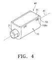
- Fig. 4 is a perspective view illustrating the hinge module assembled in accordance with an embodiment of the present invention.
- Fig. 5 is an exploded perspective view illustrating the hinge module shown in Fig. 4.
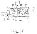
- Fig. 6 is a cross-sectional view illustrating the assembled hinge module.
- the hinge module M1 includes a hinge housing 10.
- the hinge module M1 also includes a hinge shaft 20, a hinge cam 30, and a hinge spring 40 installed in the hinge housing 10 in the direction of a rotating axis A1 in this order.
- the hinge shaft 20 and hinge cam 30 have cylindrical shapes, respectively, so that they are assembled together in the rotating axis direction.
- a hinge cover 50 is additionally assembled to the hinge housing 10 in order to protect the hinge shaft 20, hinge cam 30, and hinge spring 40 received in the hinge housing 10.
- the hinge cover 50 may be selectively used.
- the hinge cover 50 is assembled to the hinge housing 10 in the case of a flip type portable phone.
- the hinge cover 50 is not an essential element of the hinge mechanism. In the latter case, the hinge cover 50 may be selectively used.
- the hinge housing 10 is completely closed at one end thereof by a lateral end wall 101 and is partially opened at the other end thereof by a lateral end wall 102. That is, a circular hole 102a is formed through the end wall 102 in order to allow a shaft portion 21 of the hinge shaft 20 to pass therethrough.
- the hinge housing 10 is also completely opened at its upper end and is completely closed at its lower end. That is, the hinge housing 10 has an opening 103 at its upper end, and a curved bottom wall 104 at its lower end. At least one engagement hole 106a is provided at each side wall 106 of the hinge housing 10 in order to mount the hinge cover 50 to the upper end of the hinge housing 10, thereby covering the opening 103.
- the hinge housing 10 is also provided with an upper surface 105 extending around the opening 103.
- a pair of recesses 107 are formed on the upper surface 105 at opposite ends of the hinge housing 10 in the rotating axis direction, respectively.
- a guide slot 104a (shown in Fig. 6) is formed at the bottom wall 104 in such a fashion that it extends in a longitudinal direction, namely, the rotating axis direction, by a desired distance.
- the shaft portion 21 of the hinge shaft 20 extends in the rotating axis direction, namely, the Z-axis direction.
- the hinge shaft 20 also has a mountain-shaped portion 22 extending in the horizontal direction, namely, the X-axis direction, while having a pair of vertically opposite cam surfaces.
- the shaft portion 21 has a cylindrical shape in such a fashion that it is provided at opposite lateral ends thereof with a pair of facing flat surfaces 21a, respectively, and at upper and lower ends thereof with a pair of facing curved surfaces 21b, respectively.
- the direction, in which the curved surfaces 21b are opposite to each other, is perpendicular to the direction along which the mountain-shaped portion 22 extends.
- the direction, in which the flat surfaces 21a are opposite to each other, corresponds to the horizontal direction, namely, the X-axis direction.
- the direction, in which the curved surfaces 21b are opposite to each other, corresponds to the vertical direction, namely, the Y-axis direction.
- the hinge cam 30, which slides in the rotating axis direction, namely, the longitudinal direction, with respect to the hinge shaft 20, has, at one longitudinal portion thereof, a pair of vertically spaced mountain-shaped portions 31 defined with a valley-shaped portion 32 therebetween.
- the valley-shaped portion 32 is defined by a pair of facing cam surfaces respectively provided at the mountain-shaped portions 31.
- the cam surfaces of the mountain-shaped portions 31 are in contact with the cam surfaces of the hinge shaft 20, respectively.
- the hinge cam 30 is also provided at the other longitudinal portion thereof with a spring mounting protrusion 33 extending in the rotating axis direction.
- a guide protrusion 305 (shown in Fig. 6) is downwardly protruded from the lower surface of the hinge cam 30.
- the guide protrusion 305 is received in the guide slot 104a (shown in Fig. 6) of the hinge housing 10 so that it guides a straight movement of the hinge cam 30 in the rotating axis direction.
- the valley-shaped portion 32 defined between the mountain-shaped portions 31 extends horizontally.
- the hinge spring 40 is installed between the hinge cam 30 and the completely closed end wall 101 of the hinge housing 10.
- One end 41 of the hinge spring 40 is in contact with a surface 34 formed around the spring mounting protrusion 33 whereas the other end 42 of the hinge spring 40 is in contact with the completely closed end wall 101 of the hinge housing 10. Accordingly, the spring force of the hinge spring 40 is applied in the rotating axis direction A1. Since the hinge spring 40 is fitted around the spring mounting protrusion 33 at one end thereof, its separation is prevented.
- the hinge cover 50 has a flat upper surface 51 and a curved lower surface 52.
- the curved lower surface 52 is adapted to support the hinge shaft 20 and hinge cam 30.
- the hinge cover 50 is also provided at opposite longitudinal ends thereof with a pair of opposite protrusions 53 to be engaged with the recesses 107, respectively. At least one engagement protrusion 505 is protruded from each side surface of the hinge cover 50.
- the assembling of the hinge module M1 which has the above mentioned configuration, is achieved by arranging the hinge shaft 20, hinge cam 30, and hinge spring 40, in this order, in the hinge housing 10, and then coupling the hinge cover 50 to the opening 103 of the hinge housing 10.
- the shaft portion 21 of the hinge shaft 20 is exposed outwardly from the hinge housing 10, as shown in Fig. 4.
- the shaft portion 21 of the hinge shaft 20 is coupled to the associated hinge socket 2100 (shown in Fig. 7) of the flip cover 2000 so that it rotates in accordance with the opening and closing operations of the flip cover 2000.
- the hinge cam 30 slides along the hinge shaft 20 while conducting a straight reciprocal movement along the guide slot 104a, as shown in Fig. 6.
- the hinge spring 40 conducts a compression or expansion movement along the rotating axis.
- the valley-shaped portion 32 of the hinge cam 30 is maintained in a state engaged with the mountain-shaped portion 22 of the hinge shaft 20.
- the hinge cam 30 is also maintained in a state urged toward the hinge shaft 20 by the hinge spring 40.
- the mountain-shaped portion 22 of the hinge shaft 20 extends horizontally whereas the direction, in which the mountain-shaped portions 31 of the hinge cam 30 are opposite to each other, corresponds to the vertical direction.
- the shaft portions 21 of the hinge modules are exposed outwardly from opposite ends 1051 of the hinge arm 1050, respectively, as shown in Fig. 7.
- the hinge sockets 2100 of the flip cover 2000 are fitted around the exposed shaft portions 21 of the hinge modules in the rotating axis direction, respectively.
- Each of the hinge sockets 2100 has a fitting portion 2110 adapted to be fitted around an associated one of the shaft portions 21.
- the fitting portion 2110 has a shape corresponding to that of the associated shaft portion 21 including the flat and curved surfaces.
- FIG. 8 illustrates the case in which the hinge modules M1 and M2 are mounted in a symmetrical manner in the receiving portion of the hinge arm 1050 included in the phone body.
- Fig. 9 illustrates the case in which the hinge modules M1 and M2 are mounted in an asymmetrical manner in the receiving portion of the hinge arm 1050 included in the phone body.
- Fig. 10 illustrates the case in which only one hinge module M1 is mounted in the receiving portion of the hinge arm 1050. It is possible to change the opening and closing angle range of the flip cover by appropriately selecting a desired one of the various hinge module mounting methods.
- the hinge modules M1 and M2 are mounted in a symmetrical manner in the hinge arm 1050 included in the phone body.
- the hinge modules M1 and M2 of the present invention are mounted in the receiving portion of the upper casing frame 1001 in such a fashion that they are symmetric to each other in the rotating axis direction A1, as shown in Fig. 8, the hinge housing 10, hinge shaft 20, hinge cam 30, and hinge spring 40 of each hinge module are arranged in this order in the rotating axis direction A1 while being symmetric to those of the other hinge module.
- the mountain-shaped portion 22 of the hinge shaft 20 is engaged with the valley-shaped portion 32 of the hinge cam 30.
- One end 41 of the hinge spring 40 is in contact with the surface 34 of the hinge cam 30 whereas the other end 42 of the hinge spring 40 is in contact with the closed end wall 101 of the hinge housing 10.
- the mountain-shaped portion 22 of the hinge shaft 20 extends horizontally in such a fashion that their cam surfaces are vertically opposite to each other, and the valley-shaped portion 32 of the hinge cam 30 also extends horizontally in such a fashion that the cam surfaces defining the valley-shaped portion 32 face each other in the vertical direction.
- the hinge modules M1 and M2 are mounted in an asymmetrical manner in the receiving portion of the hinge arm 1050 included in the phone body. As shown in Fig. 9, the hinge module M1 is mounted in such a fashion that it is directed in an upward direction (Y-axis direction) whereas the hinge module M2 is mounted in such a fashion that it is directed in an inward direction of the phone body.
- the mountain-shaped portion 22 of the hinge shaft 20 is arranged in such a fashion that its cam surfaces are vertically opposite to each other, and the mountain-shaped portions 31 of the hinge cam 30 are arranged in such a fashion that their cam surfaces are vertically opposite to each other.
- the mountain-shaped portion 22 of the hinge shaft 20 is arranged in such a fashion that its cam surfaces are horizontally opposite to each other, and the mountain-shaped portions 31 of the hinge cam 30 are arranged in such a fashion that their cam surfaces are horizontally opposite to each other.
- shaft portions 21 of the hinge modules M1 and M2, which are exposed outwardly from opposite ends 1051 of the hinge arm 1050, respectively, are arranged in such a fashion that they are asymmetric to each other.
- the hinge modules M1 and M2 which have the same configuration, are mounted to the upper casing frame 1001 of the phone body in such a fashion that they are asymmetric to each other.
- the engaging position of the hinge shaft 20 with respect to the associated hinge cam 30 in the hinge module M1 is varied from that of hinge module M2 when the shaft portions 21 of the hinge modules M1 and M2 are fitted in the hinge sockets 2100 of the flip cover 2000.
- only the opening and closing angle range of the flip cover is changed from that of the case shown in Fig. 8.
- a hinge dummy M3 is mounted in such a fashion that it is integral with the receiving portion.
- the hinge dummy M3 has an axially extending hole 205 adapted to increase the rigidity of the hinge dummy M3. In this case, the space utilization of the phone body can be maximized because the other hinge module M2 is dispensed with.
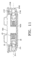
- Fig. 11 is a cross-sectional view illustrating the state in which the flip cover 2000 is coupled to two hinge modules M1 and M2 symmetrically mounted in the receiving portion of the upper casing frame 1001.
- the hinge modules M1 and M2 are fitted in the hinge sockets 2100 of the flip cover 2000, respectively, so that they apply, to the flip cover 2000, a force adapted to urge the flip cover 2000 to be opened in an on-hook state and a force adapted to prevent the flip cover 2000 from being pivotally moved in an off-hook state.
- Such a function of the hinge modules M1 and M2 is achieved in accordance with a cooperation of the hinge shaft 20, hinge cam 30 and hinge spring 40 included in each hinge module.
- the forces applied to the flip cover 2000 are generated from the hinge springs 40.
- a desired conversation angle (in the off-hook state) and a desired call waiting angle (in the on-hook state) of the flip cover 2000 are obtained in accordance with rotating movements of the hinge shafts 20, straight sliding movements of the hinge cams 30, and cam operations between the hinge shafts 20 and the associated hinge cams 30.
- the angle, at which the flip cover 2000 is prevented from being pivotally moved corresponds to a general conversation angle of, for example, 135°.
- the opening and closing angle range of the flip cover 2000 may be varied by varying the angular position of the shaft portion 21 in each hinge shaft and the angular position of the fitting portion 2110 in each hinge socket 2100.
- the opening and closing angle range of the flip cover 200 is about 130° to about 150°.
- the opening and closing angle range of the flip cover 200 is varied. In other words, when the angular position of the shaft portion 21 in each hinge shaft 20 is varied, the opening and closing angle range of the flip cover 200 is varied.
- Fig. 12 is a perspective view illustrating a hinge module having a configuration according to a second embodiment of the present invention.
- Fig. 13 is an exploded perspective view illustrating the hinge module according to the second embodiment of the present invention.
- the hinge module configuration according to the second embodiment of the present invention is similar or identical to that according to the first embodiment, except for the configurations of the hinge housing 10 and hinge cover 50. Accordingly, the hinge module configuration according to the second embodiment of the present invention will be described only in association with the configurations of the hinge housing 10 and hinge cover 50 while referring to Figs. 12 and 13.
- the means for assembling the hinge cover 50 to the hinge housing 10 comprises a pair of hinge holes 106b respectively perforated through both side walls 106 of the hinge housing 10 at one upper corner of the hinge housing 10, and a pair of hinge protrusions 56 respectively formed at both side surfaces 54 of the hinge cover 50.
- the hinge protrusions 56 are engaged with the hinge holes 106b. Accordingly, the hinge cover 50 can hinge about a rotating axis A2 with respect to the hinge housing 10 in order to open and close the hinge housing 10.
- the process of assembling the hinge cover 50 to the hinge housing 10 can be easily carried out. Also, the process of assembling the hinge shaft, hinge cam, and hinge spring in the hinge housing can be easily and accurately carried out. Accordingly, convenience is provided to the worker for conducting the assembling process. That is, the assembling process can be completed by simply hingably moving the hinge cover 50 to close the hinge housing 10 after assembling the hinge shaft 20, hinge cover 30, and hinge spring 40 in the hinge housing 10. When it is desired to disassemble the elements mounted in the hinge housing 10, this can be easily achieved by simply hingably moving the hinge cover 50 to open the hinge housing 10. In particular, it is possible to prevent the hinge cover 50 from being lost during a maintenance and repair of the hinge module.
- Fig. 14 is a perspective view illustrating a hinge module having a configuration according to a third embodiment of the present invention.
- Fig. 15 is an exploded perspective view illustrating the hinge module according to the third embodiment of the present invention.
- the hinge module configuration according to the third embodiment of the present invention is similar or identical to that according to the first embodiment, except for the configuration of the hinge housing 10 and the configuration of a hinge cover 108. Accordingly, the hinge module configuration according to the third embodiment of the present invention will be described only in association with the configurations of the hinge housing 10 and hinge cover 108 while referring to Figs. 14 and 15.
- the hinge cover 108 is coupled to the hinge housing 10 by a connecting member 109 in such a fashion that it is integral with the hinge housing 10, as shown in Figs. 14 and 15.
- the connecting member 109 is made of a flexible material while having a structure having a small thickness so that it serves as a hinge member for the hinge cover 108.
- the flexible material of the hinge member 109 may be a plastic material.
- the hinge member 109 is connected at one end thereof to the closed end wall 101 of the hinge housing 10 and at the other end thereof to one end of the hinge cover 108 so as to integrally connect the hinge housing 10 and hinge cover 108 together. Since the hinge member 109 has a flexibility, the hinge cover 108 can hingably move to open and close the hinge housing 10.
- the hinge cover 108 has opposite side surfaces 108a, a flat upper surface 108c, and a curved lower surface 110. At least one engagement protrusion 108b is protruded from each side surface 108.
- the hinge cover 108 also has a protrusion 108d to be engaged with the recess 107 of the hinge housing 10.
- Fig. 16 is a bottom view illustrating a state in which hinge modules having a configuration according to a fourth embodiment of the present invention are mounted in a symmetrical manner in the receiving portion defined in the upper casing frame 1001 of the phone body 1000.
- the hinge modules M1 and M2 are symmetrically mounted in the receiving portion of the upper casing frame 1001 in such a fashion that a space 1005 is defined therebetween.
- the space 1005 defined between the hinge modules M1 and M2 is adapted to install a microphone unit therein.
- walls 1006 and 1007 are formed at the upper casing frame 1001.
- Fig. 17 is an exploded perspective view illustrating the configuration of one hinge module according to the fourth embodiment of the present invention.
- the hinge modules M1 and M2 have the same configuration and are mounted in a symmetrical manner in the receiving portion of the phone body 1000. Accordingly, the following description will be made only in conjunction with one module, namely, the module M1. No description will be made for the other module M2.
- the hinge mechanism of the present invention includes two hinge modules which are assembled in the receiving portion provided at the lower end of the upper casing frame 1001.
- Fig. 16 illustrates the case in which the hinge modules are symmetrically mounted, those hinge modules may be mounted in an asymmetric manner. Furthermore, it is possible to mount only one hinge module.
- Such different configurations of the hinge mechanism result in only a variation in the opening and closing angle range of the flip cover 2000. Those different configurations of the hinge mechanism will be described in detail, in conjunction with Figs. 20 to 22.
- the hinge module M1 includes a hinge housing 10, a hinge shaft 210 mounted in the hinge housing 10, and a hinge spring 40 mounted in the hinge housing 10 while being fitted around the hinge shaft 210.
- the hinge shaft 210 and hinge spring 40 are disposed in the direction of a rotating axis A1.
- the hinge housing 10 is completely closed at one end thereof when viewed in the rotating axis direction A1 by a lateral end wall 112 and partially opened at the other end thereof by a lateral end wall 111.
- the hinge housing 10 is also completely opened at its upper end and completely closed at its lower end. That is, the hinge housing 10 has an opening 114 at its upper end, and a curved bottom wall 113 at its lower end.
- the hinge housing 10 has a flat surface 115 arranged around the opening 114.
- the curved bottom wall 113 has a semi-cylindrical shape.
- the partially opened end wall 111 of the hinge housing 10 has a C-shaped structure. That is, the partially opened end wall 111 is provided with two holes 111a and 111b.
- the hole 111a allows a shaft portion 211 of the hinge shaft 210 to extend therethrough in the rotating axis direction A1 whereas the hole 111b allows the shaft portion 211 to be downwardly inserted into the hole 111a therethrough when the hinge shaft 210 is assembled.
- a mountain-shaped protrusion 116 is protruded from the completely closed end wall 112 of the hinge housing 10 in the rotating axis direction A1 in the interior of the hinge housing 10.
- the mountain-shaped protrusion 116 also extends vertically (namely, in the Y-axis direction) while having a uniform mountain-shaped cross section.
- the mountain-shaped protrusion 116 serves as a fixed cam having a pair of horizontally opposite cam surfaces.
- the hinge shaft 210 has a cylindrical construction and is provided with a cam 212 engaging with the mountain-shaped protrusion 116 and serving to slide on the cam surfaces of the mountain-shaped protrusion 116 during a rotation of the hinge shaft 210, thereby moving the hinge shaft 210 in the longitudinal direction.
- the shaft portion 211 of the hinge shaft 210 extends from the cam 212 in the rotating axis direction A1.
- the cam 212 has a pair of horizontally spaced mountain-shaped portions 212a defined with a valley-shaped portion 212b therebetween.
- the valley-shaped portion 212b is defined by a pair of horizontally facing cam surfaces respectively provided at the mountain-shaped portions 212a in such a fashion that it extends vertically (namely, in the Y-axis direction).
- the cam surfaces of the mountain-shaped portions 212a are in contact with the cam surfaces of the mountain-shaped protrusion 116, respectively.
- the shaft portion 211 is provided at opposite lateral ends thereof with a pair of facing flat surfaces 211a, respectively, and at upper and lower ends thereof with a pair of facing curved surfaces 211b, respectively.
- the hinge shaft 210 also has a stepped portion at a connection between the cam 212 and shaft portion 211.
- the stepped portion has an annular surface 213.
- the mountain-shaped portions 212a of the hinge shaft 210 horizontally face each other.
- the flat surfaces 211a of the shaft portion 211 vertically face each other whereas the curved surfaces 211b of the shaft portion 211 horizontally face each other.
- the hinge spring 40 is arranged between the hinge shaft 210 and hinge housing 10 in such a fashion that it is fitted around the shaft portion 211 of the hinge shaft 210. In a state in which the hinge shaft 210 is assembled in the hinge housing 10, the hinge spring 40 is in contact with the annular surface 205 of the hinge shaft 210 at one end thereof and with the partially opened end wall 111 (namely, the C-shaped surface) of the hinge housing 10. The hinge spring 40 conducts a compression or expansion movement with respect to the shaft portion 211 of the hinge shaft 210.
- Figs. 18 and 19 illustrate the state in which the hinge shaft 210 and hinge spring 40 are assembled in the hinge housing 10.
- the mountain-shaped protrusion 116 of the hinge housing 10 is in a state engaged with the valley-shaped portion 212b of the hinge shaft 210.
- the hinge spring 30 is in a state in which it is fitted around the shaft portion 211 of the hinge shaft 210 while being supported by the hinge housing 10 and shaft portion 211 at both ends thereof, respectively.
- the free end of the hinge shaft 210 is protruded outwardly from the hinge housing 10.
- Fig. 20 is a cross-sectional view taken along the line X - X of Fig. 16, illustrating the state in which two hinge modules having the configuration according to the fourth embodiment of the present invention are symmetrically mounted in the receiving portion of the phone body 1000.
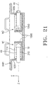
- Fig. 21 is a cross-sectional view illustrating the state in which two hinge modules having the configuration according to the fourth embodiment of the present invention are asymmetrically mounted in the receiving portion of the phone body 1000.
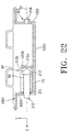
- Fig. 22 is a cross-sectional view illustrating the state in which only one hinge module having the configuration according to the fourth embodiment of the present invention is mounted in the receiving portion of the phone body 1000.
- the hinge modules M1 and M2 may be mounted in the receiving portion provided at the hinge arm 1050 of the phone body 1000 in a symmetric or asymmetric manner. Alternatively, only one hinge module M1 may be mounted in the receiving portion of the hinge arm 1050.
- the opening and closing angle range of the flip cover is changed by appropriately selecting a desired one of the various hinge module mounting methods. That is, the opening and closing angle range of the flip cover is varied by varying the engaging position of the hinge shaft 211 with respect to the hinge protrusion 116 in each hinge module.
- the opening and closing angle range of the flip cover can be varied by varying the angle defined between the cam surfaces of the mountain-shaped protrusion 116 formed at the hinge housing 10 or the angle defined between the cam surfaces provided at the mountain-shaped portion 212a of the hinge shaft 210.
- the hinge modules M1 and M2 are mounted in a symmetrical manner in the hinge arm 1050 included in the phone body 1000.
- the hinge modules M1 and M2 of the present invention are mounted in the receiving portion of the upper casing frame 1001 in such a fashion that they are symmetric to each other in the rotating axis direction A1, as shown in Fig. 20, the hinge housing 10, hinge shaft 210, and hinge spring 40 of each hinge module are arranged in this order in the rotating axis direction A1 while being symmetric to those of the other hinge module.
- the mountain-shaped protrusion 116 of the hinge housing 10 is engaged with the valley-shaped portion 212b of the cam 212.
- One end 41 of the hinge spring 40 is in contact with the annular surface 213 of the hinge shaft 210 whereas the other end 42 of the hinge spring 40 is in contact with the partially opened end wall 111 of the hinge housing 10.
- the hinge spring 40 is maintained in a maximum expansion state when the portable phone is in an on-hook or off-hook state.
- the free end of the shaft portion 211 is exposed outwardly from the associated end 1051 of the hinge arm 1050.
- the mountain-shaped portion 116 of the hinge housing 10 extends vertically in such a fashion that its cam surfaces face each other in the horizontal direction.
- the valley-shaped portion 212b of the cam 212 also extends vertically. That is, the cam surfaces of the mountain-shaped portions 212a of the cam 212 face each other in the horizontal direction.
- the mountain-shaped portions 212a and valley-shaped portion 212b of the cam 212 conduct a slide movement on the mountain-shaped protrusion 116 of the hinge housing 10.
- the hinge spring 40 is rendered to be in a maximum compression state.
- the hinge modules M1 and M2 are mounted in an asymmetrical manner in the receiving portion of the hinge arm 1050 included in the phone body. As shown in Fig. 21, the hinge module M1 is mounted in such a fashion that it is directed in an upward direction whereas the hinge module M2 is mounted in such a fashion that it is directed in an inward direction of the phone body.
- the mountain-shaped portions 212a of the hinge shaft 210 are arranged in such a fashion that their cam surfaces face each other in the horizontal direction, and the mountain-shaped protrusion 116 of the hinge housing 10 extends vertically in such a fashion that its cam surfaces are horizontally opposite to each other.
- the mountain-shaped portions 212a of the hinge shaft 210 are arranged in such a fashion that its cam surfaces face each other in the vertical direction, and the mountain-shaped protrusion 116 of the hinge housing 10 extends horizontally in such a fashion that its cam surfaces are vertically opposite to each other.
- shaft portions 211 of the hinge modules M1 and M2, which are exposed outwardly from opposite ends 1051 of the hinge arm 1050, respectively, are arranged in such a fashion that they are asymmetric to each other.
- the hinge modules M1 and M2 which have the same configuration, are mounted to the upper casing frame 1001 of the phone body in such a fashion that they are asymmetric to each other. In this case, accordingly, only the opening and closing angle range of the flip cover is changed from that of the case shown in Fig. 20.
- hinge module M1 only one hinge module, namely, the hinge module M1, is mounted in the left part of the receiving portion of the upper casing frame 1001.
- a hinge dummy M3 is mounted in such a fashion that it is integral with the receiving portion.
- the hinge dummy M3 extends in the rotating axis direction.
- the hinge dummy M3 has an axially extending hole 206 adapted to increase the rigidity of the hinge dummy M3. In this case, the space utilization of the phone body can be maximized because the other hinge module M2 is dispensed with.
- the hinge dummy M3 only serves to axially support the flip cover. That is, the hinge dummy M3 has no influence on the opening and closing angle range of the flip cover.
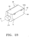
- Fig. 23 is a perspective view illustrating an assembled state of a hinge module having a configuration according to a fifth embodiment of the present invention.
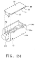
- Fig. 24 is a perspective view illustrating the hinge module according to the fifth embodiment of the present invention in which the hinge cover is separated from the hinge housing.
- the hinge module includes a hinge housing 10, a hinge shaft 210 arranged in the interior of the hinge housing 10, a hinge spring 40 fitted around the hinge shaft 210 in the hinge housing 10, and a hinge cover 50 coupled to the hinge housing 10 to provide an improvement in the efficiency of the assembling process.
- the hinge module configuration according to the fifth embodiment of the present invention is similar or identical to that according to the fourth embodiment, except for the configurations of the hinge housing 10 and hinge cover 50. Accordingly, the hinge module configuration according to the fifth embodiment of the present invention will be described only in association with the configurations of the hinge housing 10 and hinge cover 50 while referring to Figs. 23 and 24.
- the hinge housing 10 has opposite side walls 106 each provided with at least one hole 106a at a desired position.
- the hinge cover 50 has opposite side surfaces 401 each provided with at least one engagement protrusion 55 adapted to engage with an associated one of the holes 106a.
- a hinge means is provided in order to hingably couple the hinge cover 50 to the hinge housing 10. By the hinge means, the hinge cover 50 can move hingably with respect to the hinge housing 10.
- the hinge means comprises a pair of hinge protrusions 56 respectively provided at opposite side surfaces of the hinge cover 50 and a pair of hinge holes 106b respectively provided at opposite side walls 106 of the hinge housing 10. Since the hinge cover 50 is hingably coupled to the hinge housing 10, an improvement in the efficiency of the assembling process is achieved. An improvement in productivity is also obtained.
- Fig. 25 is a perspective view illustrating an assembled state of a hinge module having a configuration according to a sixth embodiment of the present invention.
- Fig. 26 is a perspective view illustrating the hinge module according to the sixth embodiment of the present invention in which the hinge cover is separated from the hinge housing.
- the hinge module includes a hinge housing 10, a hinge shaft 210 arranged in the interior of the hinge housing 10, a hinge spring 40 fitted around the hinge shaft 210 in the hinge housing 10, and a hinge cover 50 integrally molded with the hinge housing 10 to provide an improvement in the efficiency of the assembling process.
- the hinge module configuration according to the sixth embodiment of the present invention is similar or identical to that according to the fifth embodiment, except for the configurations of the hinge housing 10 and hinge cover 50. Accordingly, the hinge module configuration according to the sixth embodiment of the present invention will be described only in association with the configurations of the hinge housing 10 and hinge cover 50 while referring to Figs. 25 and 26.
- the hinge housing 10 has opposite side walls 106 each provided with at least one hole 106a at a desired position.
- the hinge cover 50 has opposite side surfaces 108a each provided with at least one engagement protrusion 108b adapted to engage with an associated one of the holes 106a.
- the holes 106a and engagement protrusions 108b provide a means for keeping the hinge cover 50 in a state closing the opening 104 of the hinge housing 10.
- the hinge cover 50 is coupled to the hinge housing 10 by a connecting member 109 in such a fashion that it is integral with the hinge housing 10.
- the hinge cover 50 is hingable with respect to the hinge housing 10 by the connecting member 109.
- the connecting member 109 is made of a flexible material while having a structure having a small thickness so that it serves as a hinge member for the hinge cover 50.
- the flexible material of the hinge member 109 may be a plastic material.
- the flexible material of the hinge member 109 may be a plastic material having an appropriate tensile strength. A thin structure made of such a plastic material may be used for the hinge member 109. Since the hinge cover 50 is hingably coupled to the hinge housing 10 by means of the hinge member 109, an improvement in the efficiency of the assembling process is achieved. An improvement in productivity is also obtained.
- the present invention has been described as being applied to flip type portable phones, it may be equivalently applied to compact terminals or other electronic appliances. Also, the present invention may be applied to folder type portable phones.
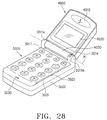
- Figs. 27 and 28 illustrate a folder type portable phone equipped with a hinge mechanism having a configuration according to a seventh embodiment of the present invention.
- Fig. 27 is a perspective view illustrating an on-hook state of the folder type portable phone whereas
- Fig. 28 is a perspective view illustrating an off-hook state of the portable phone.
- the present invention will be described in conjunction with such a folder type portable phone.
- the off-hook state corresponds to a state in which a conversation is enabled.
- the on-hook state corresponds to a state in which no conversation is enabled. That is, the off-hook state of the portable phone corresponds to a conversation mode whereas the on-hook state of the portable phone corresponds to a call waiting mode.
- the folder type portable phone includes a phone body 3000, a folder 4000, and a hinge mechanism (shown in Fig. 29) adapted to mechanically couple the folder 4000 to the phone body 3000.
- the phone body 3000 includes an upper casing frame 3001 and a lower casing frame 3002.
- An antenna unit 3010 is mounted to the upper end of the phone body 3000.
- a key pad 3020 including a plurality of function keys and numeral keys is arranged on the phone body 3000.
- a microphone unit 3030 is installed in the phone body 3000 below the key pad 3020.
- a pair of side arms 3015a and 3015b are provided at the phone body 3000 between the antenna unit 3010 and key pad 3020.
- a slot 3017 is also provided at the phone body 3000 between the side arms 3015a and 3015b.
- a call lamp 3016 is arranged at one of the side arms, namely, the side arm 3015b.
- the folder 4000 which is hingably coupled to the phone body 3000 by means of the hinge mechanism, is provided at the upper end thereof with an ear piece 4010 including a speaker.
- An LCD unit is arranged beneath the ear piece 4010.
- an LCD window 4020 is shown which is included in the LCD unit.
- a central hinge arm 4030 is formed at the lower end of the folder 4000.
- the central hinge arm 4030 has a cylindrical shape and is arranged in the slot 3017.
- the hinge mechanism is installed in the central hinge arm 4030. Accordingly, the folder 4000 can carry out hingable movements (opening and closing movements) about a rotating axis A1 with respect to the body 3000.
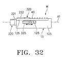
- Fig. 29 is a partially broken plan view illustrating the folder mounted with the hinge mechanism according to the seventh embodiment of the present invention.
- Fig. 30 is a cross-sectional view taken along the line X - X of Fig. 29. Now, the hinge mechanism according to the seventh embodiment of the present invention will be described in conjunction with Figs. 29 and 30.
- This hinge mechanism includes only one hinge module.
- the hinge module is mounted to the central hinge arm 4030.
- the central hinge arm 4030 which has a cylindrical shape, is opened at opposite ends 3015c and 4032 thereof.
- the hinge module which is denoted by the reference character M, is arranged in the interior of the central hinge arm 4030 at one side of the central hinge arm 4030.
- a partition wall 4031 is formed near the central portion of the hinge arm 4030.
- the portion of the hinge arm 4030 opposite to the portion, where the hinge module M is received, may provide a space for allowing a flexible printed circuit or wires extending from the speaker to pass therethrough. In the drawings, the flexible printed circuit and wires are not shown.
- the hinge module M includes a hinge housing 10.
- the hinge module M also includes a hinge shaft 220, a hinge cam 320, and a hinge spring 40 installed in the hinge housing 10 along the rotating axis A1 in this order.
- the hinge module M further includes a magnet m installed on the hinge housing 10.
- the hinge housing 10 is provided with a means for mounting the magnet m.
- Fig. 31 Detailed configurations of the constituting elements of the hinge module M will be described in conjunction with Fig. 31.
- the X-axis direction in Fig. 31 corresponds to a horizontal direction
- the Y-axis direction corresponds to a vertical direction
- the Z-axis direction corresponds to a rotating axis direction.
- the hinge housing 10 is completely closed at one end thereof when viewed in the Z-axis direction by a lateral end wall 121 and is partially opened at the other end thereof by a lateral end wall 122. That is, a circular hole 122a is formed through the end wall 122 in order to allow a shaft portion 221 of the hinge shaft 220 to pass therethrough.
- the hinge housing 10 is also completely opened at its upper end and is completely closed at its lower end. That is, the hinge housing 10 has an opening 123 at its upper end, and a curved bottom wall 124 at its lower end.
- the hinge housing 10 also has a vertical wall 125 at one end thereof when viewed in the X-axis direction. An extension 126 extends horizontally from the upper end of the vertical wall 125.
- the extension 126 has a rectangular shape and is provided with a rectangular recess 107 at its upper surface.
- the vertical wall 125 also has a guide slot 128 (shown in Fig. 32) extending in the Z-axis direction (namely, the rotating axis direction).
- folder type portable phones typically comprise a phone body, a folder, and a hinge mechanism for mechanically coupling the folder to the phone body.
- a folder type portable phone also comprises a switching means for automatically switching the operation mode of the phone between a conversation mode and a call waiting mode in accordance with the opened or closed state of the folder.
- a switching means comprises a magnet and a lead switch.
- the magnet is installed on the folder whereas the lead switch is installed on the main board arranged in the phone body.
- the recess 127 provides a space where the magnet m (shown in Fig. 29), which is a constituting element of the switching means, is installed.
- the shaft portion 221 of the hinge shaft 220 is adapted to be coupled to an associated one of the side arms 3015a and 3015b of the phone body 3000.
- the hinge shaft 220 also has a mountain-shaped portion 222 adapted to carry out a sliding movement on the hinge cam 320.
- the shaft portion 221 has a means for engaging the shaft portion 221 with the side arm in order to prevent a rotation of the shaft portion 221 with respect to the side arm.
- the means comprises a pair of opposite flat surfaces 221a and a pair of opposite curved surfaces 221b.
- the mountain-shaped portion 222 extends in the vertical direction while having a pair of horizontally opposite cam surfaces.
- the hinge shaft 220 also has an annular stepped portion 223 at a connection between the shaft portion 221 and mountain-shaped portion 222. By virtue of the annular stepped portion 223, the hinge shaft 220 is prevented from being separated in the rotating axis direction from the hinge housing 10.
- the hinge cam 320 has, at one longitudinal portion thereof, a pair of horizontally spaced mountain-shaped portions 321, and a valley-shaped portion 322 defined between the mountain-shaped portions 321.
- the valley-shaped portion 322 is defined by a pair of facing cam surfaces respectively provided at the mountain-shaped portions 321.
- the mountain-shaped portion 222 of the hinge shaft 220 is engaged with the valley-shaped portion 322 of the hinge cam 320 in such a fashion that the cam surfaces of the hinge shaft 220 are in contact with the cam surfaces of the mountain-shaped portions 321, respectively.
- the hinge cam 320 is also provided at the other longitudinal portion thereof with a spring mounting protrusion 323 extending in the rotating axis direction.
- a guide protrusion 325 is protruded from a desired portion of the hinge cam 320.
- the guide protrusion 325 is received in the guide slot 128 of the hinge housing 10 so that it guides a straight sliding movement of the hinge cam 320 in the rotating axis direction during the opening and closing operation of the folder.
- the hinge cam 320 also has an annular surface 324 formed around the spring mounting protrusion 323.
- the hinge spring 40 is installed between the annular surface 223 of the hinge cam 320 and the completely closed end wall 121 of the hinge housing 10. One end 41 of the hinge spring 40 is in contact with the annular surface 324 whereas the other end 42 of the hinge spring 40 is in contact with the completely closed end wall 121 of the hinge housing 10. Accordingly, the spring force of the hinge spring 40 is applied to the hinge cam 320 in the rotating axis direction, so that the hinge cam 320 may slide reciprocally in the rotating axis direction.
- the hinge cam 320 carries out a reciprocal straight movement guided along the guide slot 128 in the hinge housing 10 during the opening and closing operation of the folder while rotating together with the folder. At this time, the hinge shaft 220 is maintained in a fixed state. During the reciprocal straight movement of the hinge cam 320, the hinge spring 40 is repeatedly compressed and expanded along the rotating axis A1.
- the hinge spring 40 When the apex of the mountain-shaped portion 222 of the hinge shaft 220 comes into contact with the apexes of the mountain-shaped portions 321 of the hinge cam 320 during the opening and closing operation of the folder, the hinge spring 40 is rendered to be in a maximum compression state. On the other hand, when the apex of the mountain-shaped portion 222 of the hinge shaft 220 comes into contact with the bottom of the valley-shaped portion 322 of the hinge cam 320, the hinge spring 40 is rendered to be in a maximum expansion state.
- the mountain-shaped portion 222 of the hinge shaft 220 is gradually separated from the valley-shaped portion 322 of the hinge cam 320 while sliding on the cam surfaces of the mountain-shaped portions 321 of the hinge cam 320.
- the mountain-shaped portion 222 of the hinge shaft 220 comes, at its apex, into contact with the apexes of the mountain-shaped portions 321 of the hinge cam 320 and then engages again with the valley-shaped portion 322 of the hinge cam 320.
- the folder is completely open. Since the mountain-shaped portion 222 of the hinge shaft 220 is urged by the spring force of the hinge spring 40, the folder is maintained at its completely opened state.
- the hinge housing 10, hinge cam 320, and hinge spring 40 rotate along with the folder during the opening and closing operation of the folder.
- the hinge shaft 220 does not rotate because it is coupled to the associated side arm of the phone body.
- the hinge cam 320 Since the hinge shaft 220 is fixed to the side arm of the phone body, the hinge cam 320 carries out a reciprocal straight sliding movement in a direction indicated by the arrow in Fig. 32 during the opening and closing operation of the folder.
- the reciprocal straight sliding movement of the hinge cam 320 is guided by the means comprising the longitudinally extending guide slot 128 formed at the vertical wall 125 of the hinge housing 10 and the guide protrusion 325 of the hinge cam 320.
- the shaft portion 221 of the hinge shaft 220 is exposed outwardly from the central hinge arm 4030, as shown in Figs. 33 and 34.
- the exposed shaft portion 221 is fitted in a mounting hole 3015c formed at the side arm 3015b so as to couple the hinge shaft of the folder.
- a mounting hole 4032 is formed at the end of the central hinge arm 4030 opposite to the shaft portion 221 in order to receive a hinge dummy 3018 formed at the side arm 3015a.
- the hinge dummy 3018 serves as the hinge shaft of the folder.
- the hinge dummy 3018 has a hollow construction having an axial hole 3018a in order to increase the rigidity of the hinge dummy 3018, as shown in Fig. 34.
- the wires extending from the speaker or the flexible printed circuit included in the LCD unit mounted in the folder may extend through the hole 3018a so that they are electrically connected to the main board (not shown) of the phone body.
- Fig. 35 is a partially broken plan view illustrating the folder mounted with a hinge mechanism according to an eighth embodiment of the present invention.
- Fig. 36 is a cross-sectional view taken along the line X - X of Fig. 35. Now, the hinge mechanism according to the eighth embodiment of the present invention will be described in conjunction with Figs. 35 and 36.
- This hinge mechanism includes one hinge module.
- the hinge module is mounted to the central hinge arm 4030.
- the central hinge arm 4030 which has a cylindrical shape, is opened at opposite ends 3015c and 4032 thereof.
- the hinge module which is denoted by the reference character M, is arranged in the interior of the central hinge arm 4030 at one side of the central hinge arm 4030.
- a partition wall 4031 is formed near the central portion of the hinge arm 4030.
- the portion of the hinge arm 4030, opposite to the portion where the hinge module M is received, may provide a space for allowing the flexible printed circuit or the wires of the speaker to pass therethrough. In the drawings, the flexible printed circuit and wires are not shown.
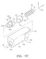
- the hinge module M includes a hinge housing 10.
- the hinge module M also includes a hinge shaft 230, a hinge cam 330, and a hinge spring 40 installed in the hinge housing 10 along the rotating axis A1 in this order.
- Figs. 37 to 39 Detailed configurations of the constituting elements of the hinge module M will be described in conjunction with Figs. 37 to 39.
- the X-axis direction in Figs. 37 to 39 corresponds to a horizontal direction
- the Y-axis direction corresponds to a vertical direction
- the Z-axis direction corresponds to a rotating axis direction.
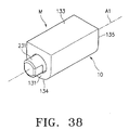
- the hinge housing 10 is partially opened at one end thereof when viewed in the direction of the rotating axis A1 by a lateral end wall 131 and is completely opened at the other end 132 thereof.
- a circular hole 131a is formed through the end wall 131 in order to allow a shaft portion 231 of the hinge shaft 230 to pass therethrough.
- the hinge housing 10 is also completely closed at its upper end by a top wall 133 and is partially opened at its lower end by a bottom wall 134.
- An extension 135 extends longitudinally from the top wall 133 so that it closes the completely opened end 132 of the hinge housing 10 in a bent state.
- the bottom wall 134 has a guide slot 134a (shown in Fig. 39) extending in the rotating axis direction (namely, the Z-axis direction).
- the shaft portion 231 of the hinge shaft 230 is adapted to be coupled to an associated one of the side arms of the phone body.
- the hinge shaft 230 also has a mountain-shaped portion 232 adapted to carry out a sliding movement on the hinge cam 330.
- the shaft portion 231 has a means for engaging the shaft portion 231 with the side arm in order to prevent a rotation of the shaft portion 231 with respect to the side arm.
- the means comprises a pair of opposite flat surfaces 231a and a pair of opposite curved surfaces 231b.
- the mountain-shaped portion 232 extends horizontally while having a pair of vertically opposite cam surfaces.
- the hinge shaft 230 also has an annular stepped portion 234 at a connection between the shaft portion 231 and mountain-shaped portion 232. By virtue of the annular stepped portion 234, the hinge shaft 230 is prevented from being separated in the rotating axis direction from the hinge housing 10.
- the hinge cam 330 has, at one longitudinal portion thereof, a pair of vertically spaced mountain-shaped portions 331, and a valley-shaped portion 332 defined between the mountain-shaped portions 331.
- the valley-shaped portion 332 is defined by a pair of facing cam surfaces respectively provided at the mountain-shaped portions 331.
- the mountain-shaped portion 232 of the hinge shaft 230 is engaged with the valley-shaped portion 332 of the hinge cam 330 in such a fashion that the cam surfaces of the hinge shaft 230 are in contact with the cam surfaces of the mountain-shaped portions 331, respectively.
- the hinge cam 330 is also provided at the other longitudinal portion thereof with a spring mounting protrusion 333 extending in the rotating axis direction.
- a guide protrusion 334 is protruded from a desired portion of the hinge cam 330.
- the guide protrusion 334 is received in the guide slot 134a of the hinge housing 10 so that it guides a straight sliding movement of the hinge cam 330 in the rotating axis direction during the opening and closing operation of the folder.
- the hinge spring 40 is installed between the hinge cam 330 and the bent extension 135 completely closing the end 132 of the hinge housing 10 in such a fashion that it is in contact with the hinge cam 330 at one end 41 thereof and with the bent extension 135 at the other end 42 thereof. Accordingly, the spring force of the hinge spring 40 is applied to the hinge cam 330 in the rotating axis direction, so that the hinge cam 330 may slide reciprocally in the rotating axis direction.
- the hinge cam 330 carries out a reciprocal straight movement guided along the guide slot 134a in the hinge housing 10 during the opening and closing operation of the folder while rotating together with the folder. At this time, the hinge shaft 230 is maintained in a fixed state. During the reciprocal straight movement of the hinge cam 330, the hinge spring 40 is repeatedly compressed and expanded along the rotating axis A1.
- the hinge spring 40 When the apex of the mountain-shaped portion 232 of the hinge shaft 230 comes into contact with the apexes of the mountain-shaped portions 331 of the hinge cam 330 during the opening and closing operation of the folder, the hinge spring 40 is rendered to be in a maximum compression state. On the other hand, When the apex of the mountain-shaped portion 232 of the hinge shaft 230 comes into contact with the bottom of the valley-shaped portion 332 of the hinge cam 330, the hinge spring 40 is rendered to be in a maximum expansion state.
- the mountain-shaped portion 232 of the hinge shaft 230 is gradually separated from the valley-shaped portion 332 of the hinge cam 330 while sliding on the cam surfaces of the mountain-shaped portions 331 of the hinge cam 330.
- the mountain-shaped portion 232 of the hinge shaft 230 comes, at its apex, into contact with the apexes of the mountain-shaped portions 331 of the hinge cam 330 and then engages again with the valley-shaped portion 332 of the hinge cam 330.
- the folder is completely open. Since the mountain-shaped portion 232 of the hinge shaft 230 is urged by the spring force of the hinge spring 40, the folder is maintained at its completely opened state.
- the hinge housing 10, hinge cam 330, and hinge spring 40 rotate along with the folder during the opening and closing operation of the folder. At this time, the hinge shaft 230 does not rotate because it is coupled to the associated side arm of the phone body.
- the hinge cam 330 Since the hinge shaft 230 is fixed to the side arm of the phone body, the hinge cam 330 carries out a reciprocal straight sliding movement in a direction indicated by the arrow in Fig. 39 during the opening and closing operation of the folder.
- the reciprocal straight sliding movement of the hinge cam 330 is guided by the means comprising the longitudinally extending guide slot 134a formed at the bottom wall 134 of the hinge housing 10 and the guide protrusion 334 of the hinge cam 330.
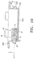
- Figs. 40 and 41 illustrate a folder type portable phone equipped with a hinge mechanism having a configuration according to a ninth embodiment of the present invention.
- Fig. 40 is a perspective view illustrating an on-hook state of the folder type portable phone whereas
- Fig. 41 is a perspective view illustrating an off-hook state of the portable phone.
- the folder type portable phone includes a phone body 5000, a folder 6000, and a hinge mechanism (not shown) adapted to mechanically couple the folder 6000 to the phone body 5000.
- the folder 6000 can hinge about a rotating axis A1 by the hinge mechanism so that it is opened and closed.
- the phone body 5000 includes an upper casing frame 5001 and a lower casing frame 5002.
- An antenna unit 5005 is mounted to the upper end of the phone body 5000.
- a central arm 5010 is centrally formed.
- a pair of side arms 5020 are formed on the upper end of the phone body 5000 at opposite sides of the central arm 5010.
- a pair of slots 5015 are defined between the central arm 5010 and the side arms 5020, respectively.
- an LCD unit 5030 is arranged on the phone body 5000.
- a key pad 5040 including a plurality of keys is arranged on the phone body 5000 below the LCD unit 5030.
- a microphone unit 5050 is installed in the phone body 5000.
- An ear piece 6010 is arranged at the upper portion of the folder 6000 coupled to the phone body 5000 by the hinge mechanism.
- a pair of hinge sockets 6020 are provided at an end of the folder 6000 opposite to the ear piece 6010. The hinge sockets 6020 are received in the slots 5015 of the phone body 5000, respectively, so that they are coupled to the hinge mechanism.
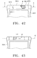
- Fig. 42 is a plan view illustrating the state in which the hinge module according to the ninth embodiment of the present invention is mounted to the upper casing frame of the phone body.
- Fig. 43 is a bottom view illustrating the hinge module mounted to the upper casing frame.
- the hinge mechanism includes one hinge module M.
- This hinge module M is installed in the central arm 5010 of the phone body.
- Fig. 44 is an exploded perspective view illustrating the configuration of the hinge module according to the ninth embodiment of the present invention.
- the X-axis direction in Fig. 44 corresponds to a horizontal direction
- the Y-axis direction corresponds to a vertical direction
- the Z-axis direction corresponds to a rotating axis direction
- the hinge module includes a hinge housing 10, a pair of hinge shafts 20-1 and 20-2, a pair of hinge cams 30-1 and 30-2, and a hinge spring 40.
- the hinge shafts 20-1 and 20-2 are symmetrically arranged in the hinge housing 10 at opposite outermost positions when viewed in the direction of the rotating axis A1, respectively.
- the hinge cams 30-1 and 30-2 are arranged in the hinge housing 10 in such a fashion that they face each other in the rotating axis direction.
- the hinge spring 40 is disposed between the hinge cams 30-1 and 30-2.
- the hinge housing 10 is partially opened at both ends thereof when viewed in the direction of the rotating axis A1 by a pair of lateral end walls, respectively. That is, circular holes 141a and 142a are formed through the end walls 141 and 142 of the hinge housing 10 in order to allow respective shaft portions 202-1 and 202-2 of the hinge shafts 20-1 and 20-2 to pass therethrough.
- the hinge housing 10 is also completely opened at its upper end and is partially opened at its lower end. That is, the hinge housing 10 has an opening 144 at its upper end, and a partially opened bottom wall 145 at its lower end.
- the hinge housing 10 also has vertical walls 146 at both ends thereof when viewed in the X-axis direction.
- the bottom wall 145 has a pair of guide slots 145a (shown in Fig.
- the hinge housing 10 has flat surfaces 146 at respective upper surfaces of the walls 143 and 144.
- the hinge housing 10 is also provided with round surfaces 147 at respective upper surfaces of the end walls 141 and 142.
- the hinge shafts 20-1 and 20-2 which are symmetrically arranged in the hinge housing 10, have shaft portions 202-1 and 202-2 at their one-end portions, respectively.
- the shaft portion 202-1 has a pair of opposite flat surfaces 203-1 and a pair of opposite curved surfaces 204-1 whereas the shaft portion 202-2 has a pair of opposite flat surfaces 203-2 and a pair of opposite curved surfaces 204-2.
- the hinge shaft 20-1 and 20-2 also have mountain-shaped portion 201-1 and 201-2 each extending horizontally (namely, in the X-axis direction) while having a pair of vertically opposite cam surfaces. In the state in which the hinge shafts 20-1 and 20-2 are mounted in the hinge housing 10, the shaft portions 202-1 and 202-2 are exposed outwardly from the hinge housing 10 through the holes 141a and 142a, respectively.
- the hinge cam 30-1 which is arranged in such a fashion that it faces the hinge shaft 20-1, has, at one longitudinal portion thereof, a pair of vertically spaced mountain-shaped portions 301-1, and a valley-shaped portion 302-1 defined between the mountain-shaped portions 301-1.
- the valley-shaped portion 302-1 is defined by a pair of facing cam surfaces respectively provided at the mountain-shaped portions 302-1.
- the mountain-shaped portion 201-1 of the hinge shaft 20-1 is engaged with the valley-shaped portion 302-1 of the hinge cam 30-1 in such a fashion that the cam surfaces of the hinge shaft 20-1 are in contact with the cam surfaces of the mountain-shaped portions 201-1, respectively.
- the hinge cam 30-1 is also provided at the other longitudinal portion thereof with a spring mounting protrusion 303-1 extending in the rotating axis direction.
- a guide protrusion 304-1 is protruded from a desired portion of the hinge cam 30-1.
- the guide protrusion 304-1 is received in the associated guide slot 145a of the hinge housing 10 so that it guides a straight sliding movement of the hinge cam 30-1 in the rotating axis direction during the opening and closing operation of the folder.
- the hinge cam 30-2, which is arranged in such a fashion that it faces the hinge shaft 20-2, has the same construction as the hinge cam 30-1. That is, the hinge cam 30-2 has a pair of vertically spaced mountain-shaped portions 301-2, and a valley-shaped portion 302-2 defined between the mountain-shaped portions 301-2.
- the valley-shaped portion 302-2 is defined by a pair of facing cam surfaces respectively provided at the mountain-shaped portions 302-2.
- the mountain-shaped portion 201-2 of the hinge shaft 20-2 is engaged with the valley-shaped portion 302-2 of the hinge cam 30-2 in such a fashion that the cam surfaces of the hinge shaft 20-2 are in contact with the cam surfaces of the mountain-shaped portions 201-2, respectively.
- the hinge cam 30-2 is also provided at the other longitudinal portion thereof with a spring mounting protrusion 303-2 extending in the rotating axis direction.
- a guide protrusion 304-2 (shown in Fig. 48) is protruded from a desired portion of the hinge cam 30-2.
- the guide protrusion 304-2 is received in the associated guide slot 145a of the hinge housing 10 so that it guides a straight sliding movement of the hinge cam 30-2 in the rotating axis direction during the opening and closing operation of the folder.
- the hinge spring 40 which is disposed between the hinge cams 30-1 and 30-2, are in contact with respective annular surfaces 305-1 and 305-2 of the hinge cams 30-1 and 30-2 at opposite ends 42 and 41, respectively. Accordingly, the spring force of the hinge spring 40 is applied to the hinge cams 30-1 and 30-2 in opposite directions along the rotating axis A1, so that the hinge cams 30-1 and 30-2 may slide reciprocally in the rotating axis direction. In other words, the hinge spring 40 is expanded and compressed in the rotating axis direction.
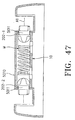
- Figs. 45 and 46 show the state in which the hinge shafts 20-1 and 20-2, hinge cams 30-1 and 30-2 and hinge spring 40 are assembled together in the hinge housing 10.
- the hinge shafts 20-1 and 20-2 are symmetrically arranged in the hinge housing 10 at opposite outermost positions when viewed in the direction of the rotating axis A1, respectively, in such a fashion that they are rotatable with respect to the hinge housing 10.
- the hinge cams 30-1 and 30-2 are arranged in the hinge housing 10 in such a fashion that they are slidable along the guide slots 145a, respectively.
- the hinge spring 40 is disposed between the hinge cams 30-1 and 30-2 in such a fashion that they are compressed and expanded along the rotating axis direction.
- the mountain-shaped portions 201-1 and 201-2 of the hinge shafts 20-1 and 20-2 extend horizontally in such a fashion that the cam surfaces of each mountain-shaped portion are vertically opposite to each other.
- the valley-shaped portions 302-1 and 302-2 of the hinge cams 30-1 and 30-2 also extend horizontally in such a fashion that the cam surfaces defining each valley-shaped portion face each other in the vertical direction.
- the hinge spring 40 extends in the rotating axis direction.
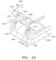
- the hinge module M which is in an independently assembled state, is mounted to the central arm 5010 in such a fashion that their shaft portions 202-1 and 202-2 extend outwardly through holes 5011 formed at opposite ends of the central arm 5010, respectively.
- the hinge module M is supported by the central arm 5010 at opposite ends thereof corresponding to the shaft portions 202-1 and 202-2.
- the central arm 5010 has a semi-cylindrical shape at its upper wall so that it conforms to the hinge housing 10.
- the hinge sockets 6020 of the folder 6000 are received in the slots 5015 of the phone body 5000 defined between the central arm 5010 and the side arms 5020 in such a fashion that they are fitted around the shaft portions 202-1 and 202-2, respectively.
- the folder 6000 is hingably mounted to the phone body 5000 by the hinge mechanism.
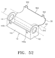
- the hinge shafts 202-1 and 202-2 rotate in a direction indicated by the arrow b in Fig. 48 along with the folder 6000.
- the hinge cams 30-1 and 30-2 carry out a reciprocal straight movement in a direction indicated by the arrow c in Fig. 48 while sliding on the hinge shafts 202-1 and 202-2, respectively.
- the hinge spring 40 is expanded or compressed in accordance with the sliding movements of the hinge cams 30-1 and 30-2.
- the sliding movements of the hinge cams 30-1 and 30-2 are guided by their guide protrusions 304-1 and 304-2 received in the guide slots 145a.
- the hinge spring 40 is compressed.
- the hinge spring 40 is expanded by its resilience.
- each hinge socket 6020 has a hole 6021 for receiving an associated one of the shaft portions 202-1 and 202-2.
- the hole 6021 has the same shape as the associated shaft portion. That is, the hole 6021 has a pair of curved surfaces 6022 and a pair of flat surfaces 6023.
- the folder 6000 is coupled to the hinge module mounted in the central arm 5010 of the upper casing frame 5001 in such a fashion that it carries out an opening and closing movement.
- the opening and closing angle range of the folder 6000 is limited up to about 160°.
- the opening and closing angle range of the folder 6000 may be varied by varying the engaging position of each hinge shaft with respect to the associated hinge cam in a state in which the folder 6000 is mounted to the phone body 5000 by the hinge mechanism.
- the opening and closing angle range of the folder 6000 may be varied by varying the angular position of the hole 6021 formed at each hinge socket 6020.
- Fig. 50 is a cross-sectional view illustrating the hinge module M in which the hinge shafts 20-1 and 20-2 and the hinge cams 30-1 and 30-2 are asymmetrically mounted in the hinge housing 10 in such a fashion that the engaging position of the hinge shaft 20-2 with respect to the associated hinge cam 30-2 is varied from that of Fig. 48 in a state in which the folder 6000 is mounted to the phone body 5000 by the hinge module M.
- the hinge shaft 20-1 is horizontally arranged in such a fashion that the cam surfaces of the mountain-shaped portion 201-1 thereof are vertically opposite to each other whereas the hinge shaft 20-2 is vertically arranged in such a fashion that the cam surfaces of the mountain-shaped portion 201-2 thereof are horizontally opposite to each other, as shown in Fig. 50.
- the shaft portion 201-2 of the hinge shaft 20-2 is fitted in the associated hinge socket 6020 of the folder 6000 in a state in which its engaging position with respect to the associated hinge cam 30-2 is varied from that of Fig. 48. Accordingly, it is possible to vary the opening and closing angle range of the folder 6000 from that in the case of Fig. 48.
- Fig. 51 is a perspective view illustrating a hinge module having a configuration according to a tenth embodiment of the present invention.
- the hinge module of this embodiment has the same configuration as that of the ninth embodiment, except for the configuration of the hinge housing 10.
- the hinge housing 10 according to the tenth embodiment has a configuration capable of achieving an improvement in the efficiency of the assembling process. Now, this hinge housing will be described in detail, in conjunction with Fig. 51.
- a hinge cover 50 is assembled to the hinge housing 10.
- the hinge cover 50 serves to protect the hinge shafts, hinge cams, and hinge spring received in the hinge housing 10.
- the hinge cover 50 extends longitudinally (namely, in the direction of a rotating axis A1) and has a C-shaped cross section. That is, the hinge cover 50 has opposite longitudinal ends 501 having a C shape.
- the hinge cover 50 is hingably coupled to the hinge housing 10 by a hinge means.
- the hinge means comprises a pair of hinge protrusions 503 provided at both ends 501 of the hinge cover 50, and a pair of hinge holes 148 provided at both end walls 141 and 142 of the hinge housing 10.
- the hinge protrusions 503 are engaged with the hinge holes 148, thereby causing the hinge cover 50 to be hingably coupled to the hinge housing in such a fashion that the hinge cover 50 hinges about a rotating axis A2.
- At least one locking protrusion 502 is provided at an end 504 of the hinge cover 50 opposite to the hinge protrusions 503 when viewed in the X-axis direction.
- At least one locking hole 143a is also formed at the wall 143 of the hinge housing 10 so that it engages with the locking protrusion 502. Since the hinge cover 50 can hinge with respect to the hinge housing 10 in accordance with the tenth embodiment of the present invention, it is possible to achieve an improvement in the efficiency of the assembling process. In addition, there is convenience in regard to maintenance and repair of the hinge module.
- Fig. 52 is a perspective view illustrating a hinge module having a configuration according to an eleventh embodiment of the present invention.
- the hinge module of this embodiment has the same configuration as that of the ninth embodiment, except for the configuration of the hinge housing 10.
- the hinge housing 10 according to the tenth embodiment has a configuration capable of achieving an improvement in the efficiency of the assembling process. Now, this hinge housing will be described in detail, in conjunction with Fig. 52.
- a hinge cover 50 is integrally connected to the hinge housing 10 by a connecting member 510 serving as a hinge means.
- This hinge means 510 is made of a plastic material while having a structure having a small thickness. Accordingly, the hinge means 510 exhibits a flexibility desired to hinge the hinge cover 50 about a rotating axis A2.
- the hinge means 510 is integrally molded with the hinge housing 10 and hinge cover 20.
- the hinge cover 50 extends longitudinally (namely, in the direction of a rotating axis A1) and has a C-shaped cross section.
- at least one locking protrusion 502 is provided at an end 504 of the hinge cover 50 opposite to the hinge means 510 when viewed in the X-axis direction.
- At least one locking hole 143a is also formed at the wall 143 of the hinge housing 10 so that it engages with the locking protrusion 502.
- the hinge mechanism of the present invention is assembled in a particular manner capable of achieving an improvement in the efficiency of the assembling process, as compared to conventional hinge mechanisms. That is, in the hinge mechanism of the present invention, the hinge cover adapted to cover the top of the hinge housing is hingably coupled to the hinge housing. This configuration provides convenience in regard to the assembling process.
- the hinge mechanism of the present invention also provides an improvement in the compactness of products.
- the hinge mechanism of the present invention can carry out stable opening and closing operations which are important for folder type and flip type portable phones because it includes hinge modules symmetrically arranged.
- the hinge mechanism of the present invention which has been described as being applied to folder type and flip type portable phones, is also applicable to any portable terminals.
Landscapes
- Engineering & Computer Science (AREA)
- Signal Processing (AREA)
- Telephone Set Structure (AREA)
- Pivots And Pivotal Connections (AREA)
Claims (15)
- Mécanisme de charnière pour téléphone portable comprenant un corps de téléphone (1000) et un clapet (2000), ledit mécanisme de charnière étant adapté pour coupler mécaniquement le clapet (2000) au corps de téléphone (1000), le mécanisme de charnière comprenant :au moins un module de charnière (M1, M2) monté sur ledit corps de téléphone (1000) et adapté pour faire pivoter ledit clapet (2000) par rapport audit corps de téléphone (1000) afin d'ouvrir et fermer ledit clapet (2000), ledit module de charnière (M1, M2) comprenant :un logement de charnière (10) possédant une paroi inférieure (104), et une paire de parois d'extrémités latérales opposées (102, 102) espacées l'une de l'autre dans une direction de l'axe de rotation, l'une desdites parois latérales (102) possédant un orifice (102a), ledit logement de charnière (10) étant complètement ouvert sur une extrémité supérieure de celui-ci et possédant également une paire de parois d'extrémités longitudinales opposées (106) espacées l'une de l'autre dans une direction normale par rapport à ladite direction de l'axe de rotation ;un arbre de charnière (20) possédant une partie en forme de montagne (22) dotée d'une paire de surfaces de came opposées sur une partie longitudinale de celui-ci et une partie d'arbre (21) sur l'autre partie longitudinale de celui-ci, ladite partie d'arbre (21) étant dotée, à une extrémité libre de celle-ci, d'une paire de surfaces planes circonférentielles opposées (21a) et d'une paire de surfaces incurvées circonférentielles opposées (21b), ledit arbre de charnière (20) étant agencé dans ledit logement de charnière (10) de telle manière que ladite partie d'arbre (21) s'étende à travers ledit orifice (102a) dudit logement de charnière (10) vers l'extérieur depuis ledit logement de charnière (10) et soit couplée audit clapet (2000), de manière à ce qu'elle pivote conjointement avec ledit clapet (2000) ;une came de charnière (30) agencée dans ledit logement de charnière (10) de telle manière qu'elle soit tournée vers ledit arbre de charnière (20) dans ladite direction de l'axe de rotation, ladite came de charnière (30) possédant, sur une partie longitudinale de celle-ci, une paire de saillies en forme de montagne (31) respectivement dotées de surfaces de came se faisant face définissant une partie en forme de vallée (32) entre les deux, et, sur l'autre partie longitudinale de celle-ci, une saillie de montage (33) s'étendant dans ladite direction de l'axe de rotation, ladite came de charnière (30) s'engageant au niveau de ladite partie en forme de vallée (32) avec ladite partie en forme de montagne (22) dudit arbre de charnière (20) de telle manière qu'elle coulisse en ligne droite dans ladite direction de l'axe de rotation en fonction de ladite rotation dudit arbre de charnière (20) ;un ressort de charnière (40) agencé dans ledit logement de charnière (10) dans ladite direction de l'axe de rotation de telle manière qu'il soit monté sur ladite saillie de montage (33) de ladite came de charnière (30) à une extrémité de celui-ci et soit en contact avec l'autre paroi d'extrémité latérale (101) dudit logement de charnière (10) à l'autre extrémité de celui-ci, ledit ressort de charnière (40) servant à pousser ladite came de charnière (30) vers ledit arbre de charnière (20) dans ladite direction de l'axe de rotation ; etun moyen (104a, 35) destiné à guider ledit mouvement de coulissement droit de ladite came de charnière (30) dans ladite direction de l'axe de rotation.
- Mécanisme de charnière selon la revendication 1, dans lequel ledit, au moins un, module de charnière comprend deux modules de charnière (M1, M2) montés dans une partie de réception dudit corps de téléphone (1000) de telle manière qu'ils soient symétriques l'un par rapport à l'autre.
- Mécanisme de charnière selon la revendication 1, dans lequel ledit, au moins un, module de charnière comprend deux modules de charnière (M1, M2) montés dans une partie de réception dudit corps de téléphone (1000) de telle manière qu'ils soient asymétriques l'un par rapport à l'autre.
- Mécanisme de charnière selon la revendication 1, dans lequel ledit, au moins un, module de charnière comprend un seul module de charnière (M1) monté dans une partie de réception dudit corps de téléphone (1000).
- Mécanisme de charnière selon l'une quelconque des revendications 1 à 4, comprenant en outre :un clapet de charnière (50) monté sur ledit logement de charnière (10) et adapté pour refermer ladite extrémité supérieure ouverte dudit logement de charnière (10).
- Mécanisme de charnière selon la revendication 5, dans lequel ledit clapet de charnière (50) possède un moyen (53, 55) destiné à coupler ledit clapet de charnière (50) audit logement de charnière (10) dans un état refermant ladite extrémité supérieure ouverte dudit logement de charnière (10).
- Mécanisme de charnière selon la revendication 5 ou 6, dans lequel ledit clapet (2000) est un clapet basculant :ledit clapet de charnière (50) étant monté de manière pivotante sur ce logement de charnière (10) et étant doté, à une extrémité longitudinale de celui-ci, d'un moyen de charnière destiné à faire pivoter ledit clapet de charnière par rapport audit logement de charnière (10).
- Mécanisme de charnière selon la revendication 7, dans lequel ledit moyen de charnière comprend une paire de saillies de charnière (56) faisant respectivement saillie depuis les extrémités latérales opposées dudit clapet de charnière (50), et une paire d'orifices de charnière (106b) respectivement formés dans lesdites parois d'extrémités latérales (106) dudit logement de charnière (10) et en prise avec lesdites saillies de charnière (56).
- Mécanisme de charnière selon la revendication 7, ledit moyen de charnière comprend un élément de connexion (109) destiné à connecter ledit clapet de charnière (50) audit logement de charnière (10), ledit élément de connexion (109) étant constitué d'un matériau plastique tout en possédant une structure présentant une petite épaisseur pour procurer une flexibilité.
- Mécanisme de charnière pour téléphone portable comprenant un corps de téléphone (1000) et un clapet (2000), ledit mécanisme de charnière étant adapté pour coupler mécaniquement le clapet (2000) au corps de téléphone (1000), le mécanisme de charnière comprenant :un logement de charnière (10) possédant une paroi inférieure (113), et une paire de parois d'extrémités latérales opposées (111, 112) espacées l'une de l'autre dans une direction de l'axe de rotation, l'une desdites parois latérales (111) possédant un orifice (111a), ledit logement de charnière (10) étant complètement ouvert sur une extrémité supérieure de celui-ci et possédant également une paire de parois d'extrémités longitudinales opposées espacées l'une de l'autre dans une direction normale par rapport à ladite direction de l'axe de rotation, et une saillie en forme de montagne (116) faisant saillie depuis l'autre desdites parois latérales (112) à l'intérieur dudit logement de charnière (10) dans ladite direction de l'axe de rotation et dotée d'une paire de surfaces de came opposées ;un arbre de charnière (210) possédant, sur une partie longitudinale de celui-ci, une partie d'arbre, (211), et, sur l'autre partie longitudinale de celui-ci, une paire de saillies en forme de montagne (212a) respectivement dotées de surfaces de came se faisant face définissant une partie en forme de vallée (212b) entre les deux, ledit arbre de charnière (210) étant agencé dans ladite direction de l'axe de rotation dans ledit logement de charnière (10) de telle manière que ladite partie d'arbre (211) s'étende à travers ledit orifice (111a) dudit logement de charnière (10) vers l'extérieur depuis ledit logement de charnière (10) et soit couplée audit clapet (2000), de manière à ce qu'elle pivote conjointement avec ledit clapet (2000) ; etun ressort de charnière (40) agencé dans ledit logement de charnière (10) dans ladite direction de l'axe de rotation de telle manière qu'il soit en contact avec ladite une paroi d'extrémité latérale (111) dudit logement de charnière (10) à une extrémité de celui-ci et avec une partie souhaitée dudit arbre de charnière (210) à l'autre extrémité de celui-ci tout en étant ajusté autour de ladite partie d'arbre (211) dudit arbre de charnière (210), ledit ressort de charnière (40) servant à pousser ledit arbre de charnière (210) vers ladite partie en forme de montagne (116) dudit logement de charnière (10) dans ladite direction de l'axe de rotation tout en étant compressé et tendu dans ladite direction de l'axe de rotation.
- Mécanisme de charnière pour un téléphone portable de type rabattable comprenant un corps de téléphone (3000) doté d'une paire de bras latéraux symétriques (3015a, 3015b) et d'une unité rabattable (4000) dotée d'un bras de charnière central (4030) interposé entre les bras latéraux (3015a, 3015b), ledit mécanisme de charnière monté dans le bras de charnière central (4030) et adapté pour coupler mécaniquement l'unité rabattable (4000) au corps de téléphone (3000), le mécanisme de charnière comprenant :un logement de charnière (10) possédant une paroi inférieure (124), et une paire de parois d'extrémités latérales opposées (121, 122) espacées l'une de l'autre dans une direction de l'axe de rotation, l'une desdites parois latérales (122) possédant un orifice (122a), ledit logement de charnière (10) étant complètement ouvert sur une extrémité supérieure de celui-ci et possédant également une paire de parois d'extrémités longitudinales opposées espacées l'une de l'autre dans une direction normale par rapport à ladite direction de l'axe de rotation ;un arbre de charnière (220) possédant une partie en forme de montagne (222) dotée d'une paire de surfaces de came opposées sur une partie longitudinale de celui-ci et une partie d'arbre (221) sur l'autre partie longitudinale de celui-ci, ledit arbre de charnière (220) étant agencé dans ledit logement de charnière (10) de telle manière que ladite partie d'arbre (221) s'étende à travers ledit orifice (122a) dudit logement de charnière (10) vers l'extérieur depuis ledit logement de charnière (10) et soit couplée à ladite unité rabattable (4000), de manière à ce qu'il pivote conjointement avec ladite unité rabattable (4000), ledit arbre de charnière (220) possédant également une partie étagée annulaire (223) agencée entre ladite partie en forme de montagne (222) et ladite partie d'arbre (221) et adaptée pour empêcher ledit arbre de charnière (220) de se séparer dudit logement de charnière (10) à travers ledit orifice (122a) dudit logement de charnière (10) ;une came de charnière (320) agencée dans ledit logement de charnière (10) de telle manière qu'elle soit tournée vers ledit arbre de charnière (220) dans ladite direction de l'axe de rotation, ladite came de charnière (320) possédant, sur une partie longitudinale de celle-ci, une paire de saillies en forme de montagne (321) respectivement dotées de surfaces de came se faisant face définissant une partie en forme de vallée (322) entre les deux, et, sur l'autre partie longitudinale de celle-ci, une saillie de montage de ressort (323) s'étendant dans ladite direction de l'axe de rotation, ladite came de charnière (320) s'engageant au niveau de ladite partie en forme de vallée (322) avec ladite partie en forme de montagne (222) dudit arbre de charnière (220) de telle manière qu'elle coulisse en ligne droite dans ladite direction de l'axe de rotation en fonction de ladite rotation dudit arbre de charnière (220) ;un ressort de charnière (40) agencé dans ledit logement de charnière (10) dans ladite direction de l'axe de rotation de telle manière qu'il soit monté sur ladite saillie de montage de ressort (323) de ladite came de charnière (320) à une extrémité de celui-ci et soit en contact avec l'autre paroi d'extrémité latérale dudit logement de charnière (10) à l'autre extrémité de celui-ci, ledit ressort de charnière (40) servant à pousser ladite came de charnière (320) vers ledit arbre de charnière (220) dans ladite direction de l'axe de rotation ; etun moyen (325, 128) destiné à guider ledit mouvement de coulissement droit de ladite came de charnière (320) dans ladite direction de l'axe de rotation.
- Mécanisme de charnière selon la revendication 11, comprenant en outre un moyen destiné à monter un aimant (m), ledit moyen étant placé sur ledit logement de charnière (10).
- Mécanisme de charnière selon la revendication 12, dans lequel ledit moyen de montage de l'aimant comprend :une extension (126) s'étendant horizontalement depuis l'une desdites parois d'extrémités longitudinales dudit logement de charnière (10) à une extrémité supérieure de ladite une desdites parois d'extrémités longitudinales ; etun enfoncement (127) formé sur une surface supérieure de ladite extension (126) et adapté pour ajuster ledit aimant (m) dans celle-ci.
- Mécanisme de charnière pour un téléphone portable de type rabattable comprenant un corps de téléphone (3000) et une unité rabattable (4000) dotée d'un bras de charnière central (4030), ledit mécanisme de charnière monté dans le bras de charnière central (4030) et adapté pour coupler mécaniquement l'unité rabattable (4000) au corps de téléphone (3000), le mécanisme de charnière comprenant :un logement de charnière (10) constitué d'un matériau métallique, ledit logement de charnière (10) possédant une paroi supérieure complètement fermée (133), une paroi inférieure partiellement ouverte (134), et une paroi d'extrémité latérale (131) agencée à une extrémité de celui-ci vu dans une direction de l'axe de rotation et partiellement ouverte par un orifice (131a) formé à travers celle-ci, ledit logement de charnière (10) étant complètement ouvert sur l'autre extrémité de celui-ci vu dans ladite direction de l'axe de rotation et possédant également une paire de parois d'extrémités longitudinales opposées espacées l'une de l'autre dans une direction normale par rapport à ladite direction de l'axe de rotation, et une extension (135) s'étendant depuis ladite paroi supérieure (133) dans ladite direction de l'axe de rotation sur ladite autre extrémité dudit logement de charnière (10), ladite extension (135) étant pliée pour refermer ladite autre extrémité dudit logement de charnière (10),un arbre de charnière (230) possédant une partie en forme de montagne (232) dotée d'une paire de surfaces de came opposées sur une partie longitudinale de celui-ci et une partie d'arbre (231) sur l'autre partie longitudinale de celui-ci, ledit arbre de charnière (230) étant agencé dans ledit logement de charnière (10) de telle manière que ladite partie d'arbre (231) s'étende à travers ledit orifice (131a) dudit logement de charnière (10) vers l'extérieur depuis ledit logement de charnière (10) et soit couplée à ladite unité rabattable (4000), de manière à ce qu'il pivote conjointement avec ladite unité rabattable (4000), ledit arbre de charnière (230) possédant également une partie étagée annulaire (234) agencée entre ladite partie en forme de montagne (232) et ladite partie d'arbre (231) et adaptée pour empêcher ledit arbre de charnière (230) de se séparer dudit logement de charnière (10) à travers ledit orifice (131a) dudit logement de charnière (10) ;une came de charnière (330) agencée dans ledit logement de charnière (10) de telle manière qu'elle soit tournée vers ledit arbre de charnière (230) dans ladite direction de l'axe de rotation, ladite came de charnière (330) possédant, sur une partie longitudinale de celle-ci, une paire de saillies en forme de montagne (331) respectivement dotées de surfaces de came se faisant face définissant une partie en forme de vallée (332) entre les deux, et, sur l'autre partie longitudinale de celle-ci, une saillie de montage de ressort (333) s'étendant dans ladite direction de l'axe de rotation, ladite came de charnière (330) s'engageant au niveau de ladite partie en forme de vallée (332) avec ladite partie en forme de montagne (232) dudit arbre de charnière (230) de telle manière qu'elle coulisse en ligne droite dans ladite direction de l'axe de rotation en fonction de ladite rotation dudit arbre de charnière (230) ;un ressort de charnière (40) agencé dans ledit logement de charnière (10) dans ladite direction de l'axe de rotation de telle manière qu'il soit monté sur ladite saillie de montage de ressort (333) de ladite came de charnière (330) à une extrémité de celui-ci et soit en contact avec ladite extension (135) refermant ladite autre extrémité dudit logement de charnière (10) à l'autre extrémité de celui-ci, ledit ressort de charnière (40) servant à pousser ladite came de charnière (330) vers ledit arbre de charnière (230) dans ladite direction de l'axe de rotation, tout en étant compressé et étendu dans ladite direction de l'axe de rotation ; etun moyen (334, 134a) destiné à guider ledit mouvement de coulissement droit de ladite came de charnière (330) dans ladite direction de l'axe de rotation.
- Mécanisme de charnière pour un téléphone portable de type rabattable comprenant un corps de téléphone (5000) doté d'un bras central (5010), d'une paire de bras latéraux (5020) agencés sur les côtés opposés de l'arbre central (5010), et d'une paire de fentes (5015) chacune définie entre le bras central (5010) et l'un associé des bras latéraux (5020), et d'une unité rabattable (6000) dotée d'une paire de douilles de charnière (6020) respectivement ajustées dans les fentes (5015), ledit mécanisme de charnière étant monté dans le bras central (5010) et adapté pour coupler mécaniquement l'unité rabattable (6000) au corps de téléphone (5000), le mécanisme de charnière comprenant :un logement de charnière (10) s'étendant dans une direction de l'axe de rotation et possédant une paroi inférieure partiellement ouverte (145), une paire de parois d'extrémités latérales (141, 142) respectivement agencées aux extrémités opposées de celui-ci vu dans ladite direction de l'axe de rotation et partiellement ouvertes par des orifices (141a, 142a) formés dans celles-ci, ledit logement de charnière (10) étant complètement ouvert à une extrémité supérieure de celui-ci et possédant également une paire de parois d'extrémités longitudinales opposées espacées l'une de l'autre dans une direction normale par rapport à ladite direction de l'axe de rotation ;une paire d'arbres de charnière (20-1, 20-2) possédant chacun une partie en forme de montagne (201-1, 201-2) dotée d'une paire de surfaces de came opposées sur une partie longitudinale de celui-ci et une partie d'arbre (202-1, 202-2) sur l'autre partie longitudinale de celui-ci, ladite partie d'arbre (202-1, 202-2) étant dotée, à une extrémité libre de celle-ci, d'une paire de surfaces planes circonférentielles opposées (203-1, 203-2) et d'une paire de surfaces incurvées circonférentielles opposées (204-1, 202-2), lesdits arbres de charnière (20-1, 20-2) étant agencés symétriquement dans ledit logement de charnière (10) de telle manière que lesdites parties d'arbre (202-1, 202-2) de ceux-ci s'étendent à travers lesdits orifices (141a, 142a) dudit logement de charnière (10) vers l'extérieur depuis ledit logement de charnière (10) et soient couplées auxdites douilles de charnière (6020) de ladite unité rabattable (6000), respectivement, de telle manière qu'elles pivotent conjointement avec ladite unité rabattable (6000) ;une paire de cames de charnière (30-1, 30-2) agencées dans ledit logement de charnière (10) de telle manière qu'elles soient tournées vers lesdits arbres de charnière (20-1, 20-2) dans ladite direction de l'axe de rotation, respectivement, chacune desdites cames de charnière (30-1, 30-2) possédant, sur une partie longitudinale de celle-ci, une paire de saillies en forme de montagne (301-1, 302-2) respectivement dotées de surfaces de came se faisant face définissant une partie en forme de vallée (302-1, 302-2) entre les deux, et, sur l'autre partie longitudinale de celle-ci, une saillie de montage (303-1, 303-2) s'étendant dans ladite direction de l'axe de rotation, chacune desdites cames de charnière (30-1, 30-2) s'engageant au niveau de ladite partie en forme de vallée (302-1, 302-2) de celle-ci avec ladite partie en forme de montagne (201-1, 202-2) de l'un associé desdits arbres de charnière (20-1, 20-2) de telle manière qu'elle coulisse en ligne droite dans ladite direction de l'axe de rotation en fonction de ladite rotation dudit arbre de charnière associé (20-1, 20-2) ;un ressort de charnière (40) agencé dans ledit logement de charnière (10) dans ladite direction de l'axe de rotation de telle manière qu'il soit monté sur lesdites saillies de montage (303-1, 302-2) desdites cames de charnière (30-1, 30-2) aux extrémités opposées de celui-ci, ledit ressort de charnière (40) servant à pousser lesdites cames de charnière. (30-1, 30-2) vers lesdits arbres de charnière (20-1, 20-2) respectivement engagés avec lesdites cames de charnière (30-1, 30-2) dans ladite direction de l'axe de rotation, tout en étant compressé et étendu dans ladite direction de l'axe de rotation ; etun moyen (145a, 304-1, 304-2) destiné à guider lesdits mouvements de coulissement droit desdites cames de charnière (30-1, 30-2) dans ladite direction de l'axe de rotation.
Applications Claiming Priority (17)
| Application Number | Priority Date | Filing Date | Title |
|---|---|---|---|
| KR9808833U | 1998-05-26 | ||
| KR9808834 | 1998-05-26 | ||
| KR9808834U | 1998-05-26 | ||
| KR19980008834 | 1998-05-26 | ||
| KR19980008833 | 1998-05-26 | ||
| KR9808833 | 1998-05-26 | ||
| KR19980011335 | 1998-06-27 | ||
| KR9811335 | 1998-06-27 | ||
| KR9811335U | 1998-06-27 | ||
| KR9815500U | 1998-08-18 | ||
| KR19980015500 | 1998-08-18 | ||
| KR9815500 | 1998-08-18 | ||
| KR19980016827 | 1998-09-04 | ||
| KR9816827 | 1998-09-04 | ||
| KR9816827U | 1998-09-04 | ||
| KR9912991 | 1999-04-13 | ||
| KR1019990012991A KR100296038B1 (ko) | 1998-05-26 | 1999-04-13 | 휴대폰의 힌지장치 |
Publications (3)
| Publication Number | Publication Date |
|---|---|
| EP0961457A2 EP0961457A2 (fr) | 1999-12-01 |
| EP0961457A3 EP0961457A3 (fr) | 2000-04-26 |
| EP0961457B1 true EP0961457B1 (fr) | 2004-11-17 |
Family
ID=27555110
Family Applications (1)
| Application Number | Title | Priority Date | Filing Date |
|---|---|---|---|
| EP99110188A Expired - Lifetime EP0961457B1 (fr) | 1998-05-26 | 1999-05-26 | Mécanisme de charnière pour téléphone portable |
Country Status (5)
| Country | Link |
|---|---|
| US (1) | US6292980B1 (fr) |
| EP (1) | EP0961457B1 (fr) |
| CN (1) | CN1197327C (fr) |
| BR (1) | BR9901642A (fr) |
| DE (1) | DE69921885T2 (fr) |
Families Citing this family (70)
| Publication number | Priority date | Publication date | Assignee | Title |
|---|---|---|---|---|
| KR100678082B1 (ko) * | 1998-12-30 | 2007-05-17 | 삼성전자주식회사 | 폴더 타입 휴대폰에서 메인 보드와 엘씨디 모듈간의연결장치 |
| JP2002039161A (ja) * | 2000-07-31 | 2002-02-06 | Nifco Inc | ヒンジユニット及びヒンジ構造 |
| JP3830745B2 (ja) * | 2000-09-29 | 2006-10-11 | スガツネ工業株式会社 | ヒンジ装置 |
| USD480717S1 (en) | 2000-11-09 | 2003-10-14 | Sugatsune Kogyo Co., Ltd. | Hinge for cellular telephone |
| US20020065054A1 (en) * | 2000-11-29 | 2002-05-30 | Morris Humphreys | Mobile station and elastomeric cover |
| JP3825627B2 (ja) * | 2000-12-14 | 2006-09-27 | スガツネ工業株式会社 | ヒンジ装置及び携帯電話器 |
| KR100383623B1 (ko) * | 2000-12-30 | 2003-05-14 | 삼성전자주식회사 | 휴대용 무선단말기의 힌지모듈 |
| JP4290989B2 (ja) * | 2001-02-26 | 2009-07-08 | スガツネ工業株式会社 | ヒンジ装置 |
| CN1305226C (zh) * | 2001-04-04 | 2007-03-14 | M2Sys株式会社 | 移动电话的铰接机构 |
| KR100665709B1 (ko) * | 2001-04-26 | 2007-01-10 | 피닉스코리아 주식회사 | 힌지장치 |
| US7006853B2 (en) * | 2001-08-24 | 2006-02-28 | Samsung Electronics Co., Ltd. | Rotary type hinge module for portable wireless terminal |
| US6968056B2 (en) * | 2001-12-21 | 2005-11-22 | Nokia Corporation | Mobile phone with elastic hinge |
| CN1647402B (zh) * | 2002-03-02 | 2010-05-05 | 莱尔德科技Map有限公司 | 便携式电话的旋转铰接机构 |
| TW556947U (en) * | 2002-06-21 | 2003-10-01 | Quanta Comp Inc | Key stroke structure |
| KR100440407B1 (ko) * | 2002-07-19 | 2004-07-14 | 삼성전자주식회사 | 힌지 장치를 이용한 그라운드 접속 장치를 구비하는휴대용 무선 단말기 |
| KR100469361B1 (ko) * | 2002-07-24 | 2005-01-31 | 삼성전기주식회사 | 휴대전화기의 폴더 구동장치 |
| US20040020012A1 (en) * | 2002-08-02 | 2004-02-05 | Gupte Sheel A. | Self-contained hinge for flip-style device |
| US20040023700A1 (en) * | 2002-08-02 | 2004-02-05 | Amphenol-T&M Antennas | Self-contained portable hinge assembly |
| US6766181B1 (en) * | 2002-08-30 | 2004-07-20 | Nokia Corporation | Folding mobile station with dual-movement hinge |
| KR100504138B1 (ko) * | 2002-11-12 | 2005-07-27 | 삼성전자주식회사 | 휴대용 무선 단말기의 힌지 장치 |
| KR100969747B1 (ko) * | 2003-01-06 | 2010-07-13 | 삼성전자주식회사 | 힌지 장치를 이용한 그라운드 접속 장치를 구비하는휴대용 무선 단말기 |
| TW570436U (en) * | 2003-01-16 | 2004-01-01 | Benq Corp | Foldable mobile phone |
| KR100490356B1 (ko) * | 2003-01-20 | 2005-05-17 | 삼성전자주식회사 | 휴대용 무선 단말기의 로터리형 힌지 장치 |
| JP4026506B2 (ja) * | 2003-02-14 | 2007-12-26 | 松下電器産業株式会社 | 開閉装置及びこれを用いた電子機器 |
| KR100513015B1 (ko) * | 2003-04-08 | 2005-09-05 | 삼성전자주식회사 | 휴대용 무선 단말기의 로터리형 힌지 장치 |
| KR100547726B1 (ko) * | 2003-04-25 | 2006-01-31 | 삼성전자주식회사 | 휴대용 무선 단말기 폴더의 회전 멈춤 장치 |
| TW572125U (en) * | 2003-05-30 | 2004-01-11 | Hon Hai Prec Ind Co Ltd | Hinge mechanism |
| US7099702B1 (en) | 2003-10-16 | 2006-08-29 | Sprint Spectrum L.P. | Portable phone having transformable components |
| TWM249424U (en) * | 2003-12-31 | 2004-11-01 | Hon Hai Prec Ind Co Ltd | Hinge |
| TWM251407U (en) * | 2004-01-09 | 2004-11-21 | Hon Hai Prec Ind Co Ltd | Hinge |
| WO2005074602A2 (fr) * | 2004-02-02 | 2005-08-18 | Amphenol-T & M Antennas | Pivot de bouton-poussoir pour dispositifs portatifs |
| TWM257399U (en) * | 2004-03-19 | 2005-02-21 | Fih Co Ltd | Hinge |
| KR100834626B1 (ko) * | 2004-05-06 | 2008-06-02 | 삼성전자주식회사 | 자기 거치 기능을 구비한 슬라이딩/스윙 타입 휴대 장치 |
| US7373692B2 (en) | 2004-06-08 | 2008-05-20 | Amphenol-T&M Antennas | Parallel plane rotation hinge for a portable device |
| US20060193469A1 (en) * | 2004-06-08 | 2006-08-31 | Tony Kfoury | Parallel plane rotation hinge for a portable device |
| KR100630097B1 (ko) * | 2004-06-09 | 2006-09-27 | 삼성전자주식회사 | 휴대용 통신 장치 |
| CN2728174Y (zh) * | 2004-07-30 | 2005-09-21 | 深圳富泰宏精密工业有限公司 | 铰链结构 |
| US7484268B2 (en) * | 2004-09-17 | 2009-02-03 | Samsung Electronics Co., Ltd. | Hinge device and portable terminal having the same |
| TWI280311B (en) * | 2004-10-22 | 2007-05-01 | Sutech Trading Ltd | Hinge and mobile phone using the hinge |
| CN100471371C (zh) * | 2004-11-11 | 2009-03-18 | 深圳富泰宏精密工业有限公司 | 铰链结构 |
| CN2757504Y (zh) * | 2004-12-03 | 2006-02-08 | 深圳富泰宏精密工业有限公司 | 铰链结构 |
| US7832055B2 (en) * | 2004-12-30 | 2010-11-16 | Sony Ericsson Mobile Communications Ab | Hinge |
| KR100689378B1 (ko) * | 2005-01-20 | 2007-03-02 | 삼성전자주식회사 | 휴대용 단말기의 힌지 장치 |
| FI117312B (fi) * | 2005-05-13 | 2006-08-31 | Nokia Corp | Elektroniikkalaitteen saranarakenne |
| KR100630138B1 (ko) | 2005-08-17 | 2006-10-02 | 삼성전자주식회사 | 휴대용 단말기의 힌지 장치 |
| KR100651497B1 (ko) | 2005-08-22 | 2006-11-29 | 삼성전자주식회사 | 휴대용 단말기의 힌지 장치 |
| CN100475013C (zh) * | 2005-09-19 | 2009-04-01 | 华硕电脑股份有限公司 | 电子装置及其枢轴机构 |
| CN1948770B (zh) * | 2005-10-14 | 2010-09-29 | 深圳富泰宏精密工业有限公司 | 铰链结构及使用该铰链结构的便携式电子装置 |
| KR100630139B1 (ko) | 2005-11-28 | 2006-10-02 | 삼성전자주식회사 | 이축 힌지 장치를 구비하는 휴대용 단말기 |
| KR20070073252A (ko) * | 2006-01-04 | 2007-07-10 | 삼성전자주식회사 | 힌지 장치를 구비하는 휴대용 단말기 |
| KR100701500B1 (ko) * | 2006-06-16 | 2007-03-29 | 주식회사 엠투시스 | 휴대 단말기용 개폐장치 |
| KR100849318B1 (ko) | 2006-08-22 | 2008-07-29 | 삼성전자주식회사 | 힌지 장치 및 그를 구비하는 휴대용 단말기 |
| KR100800711B1 (ko) * | 2006-08-23 | 2008-02-01 | 삼성전자주식회사 | 휴대 단말기의 프리 스톱 힌지 장치 |
| KR100827111B1 (ko) * | 2006-09-18 | 2008-05-02 | 삼성전자주식회사 | 휴대용 단말기의 힌지 장치 |
| KR100790175B1 (ko) * | 2006-11-16 | 2008-01-02 | 삼성전자주식회사 | 힌지 장치 및 그를 구비하는 휴대용 단말기의 작동 방법 |
| KR100802558B1 (ko) * | 2007-05-03 | 2008-02-13 | 주식회사 엠투시스 | 스텝 힌지 |
| KR20080109108A (ko) * | 2007-06-12 | 2008-12-17 | (주)엘티엠에이피 | 휴대단말기용 스텝 힌지 |
| CN101242047B (zh) * | 2008-02-26 | 2010-06-09 | 华为终端有限公司 | Usb连接件及usb装置 |
| CN102165754B (zh) * | 2008-09-25 | 2014-03-12 | 日本电气株式会社 | 折叠式便携装置、用于该装置的铰链机构、和打开该装置的方法 |
| US8732906B1 (en) * | 2009-02-18 | 2014-05-27 | Jan van Gennep | Locking hinge assembly |
| CN101859193B (zh) * | 2009-04-13 | 2013-04-24 | 鸿富锦精密工业(深圳)有限公司 | 鼠标 |
| KR20110022365A (ko) * | 2009-08-27 | 2011-03-07 | 삼성전자주식회사 | 2 개의 힌지축을 구비하는 휴대용 단말기 |
| EP2362611B1 (fr) * | 2010-02-26 | 2013-12-25 | BlackBerry Limited | Dispositif de communication mobile avec élément de couvercle mobile |
| KR20120013703A (ko) * | 2010-08-06 | 2012-02-15 | 삼성전자주식회사 | 휴대용 단말기 |
| CN102454689A (zh) * | 2010-10-25 | 2012-05-16 | 深圳富泰宏精密工业有限公司 | 铰链结构及组装该铰链结构的方法 |
| KR20150060292A (ko) * | 2013-11-26 | 2015-06-03 | 엘지전자 주식회사 | 가전 제품 |
| JP6117896B1 (ja) * | 2015-11-18 | 2017-04-19 | アトムメディカル株式会社 | 保育器 |
| US11214998B2 (en) | 2019-12-30 | 2022-01-04 | Whirlpool Corporation | Resilient retainer for a hinge assembly of an appliance door panel |
| CN116263182A (zh) * | 2021-12-15 | 2023-06-16 | Oppo广东移动通信有限公司 | 扭矩组件、转轴套件、以及电子设备 |
| KR20240040219A (ko) * | 2022-09-21 | 2024-03-28 | (주)대한솔루션 | 자동차용 커버링 쉘프 또는 카고 스크린에 장착되는 마운팅 힌지 |
Family Cites Families (5)
| Publication number | Priority date | Publication date | Assignee | Title |
|---|---|---|---|---|
| UA26316C2 (uk) | 1991-05-06 | 1999-08-30 | Моторола, Інк. | Міhіатюрhий електроhhий пристрій |
| JPH08139793A (ja) | 1994-11-15 | 1996-05-31 | Kato Electrical Mach Co Ltd | 携帯用電話器の開閉装置 |
| US5628089A (en) * | 1995-05-18 | 1997-05-13 | Motorola, Inc. | Radiotelephone having a self contained hinge |
| KR200141099Y1 (ko) * | 1995-09-19 | 1999-05-15 | 김광호 | 휴대용 전화기의 버튼커버 개페장치 |
| KR100266516B1 (ko) * | 1998-05-18 | 2000-09-15 | 한영수 | 힌지장치 |
-
1999
- 1999-05-26 BR BR9901642-7A patent/BR9901642A/pt not_active Application Discontinuation
- 1999-05-26 CN CN99109493.XA patent/CN1197327C/zh not_active Expired - Fee Related
- 1999-05-26 US US09/320,506 patent/US6292980B1/en not_active Expired - Lifetime
- 1999-05-26 EP EP99110188A patent/EP0961457B1/fr not_active Expired - Lifetime
- 1999-05-26 DE DE69921885T patent/DE69921885T2/de not_active Expired - Lifetime
Also Published As
| Publication number | Publication date |
|---|---|
| DE69921885T2 (de) | 2006-02-09 |
| CN1241863A (zh) | 2000-01-19 |
| CN1197327C (zh) | 2005-04-13 |
| BR9901642A (pt) | 2000-01-18 |
| EP0961457A3 (fr) | 2000-04-26 |
| DE69921885D1 (de) | 2004-12-23 |
| EP0961457A2 (fr) | 1999-12-01 |
| US6292980B1 (en) | 2001-09-25 |
Similar Documents
| Publication | Publication Date | Title |
|---|---|---|
| EP0961457B1 (fr) | Mécanisme de charnière pour téléphone portable | |
| US6438228B1 (en) | Hinge device of mobile telephone | |
| US20050202856A1 (en) | Swing-type portable terminal | |
| KR100678082B1 (ko) | 폴더 타입 휴대폰에서 메인 보드와 엘씨디 모듈간의연결장치 | |
| KR100490356B1 (ko) | 휴대용 무선 단말기의 로터리형 힌지 장치 | |
| KR100283185B1 (ko) | 출몰식 스피커 장치 | |
| EP1693539A2 (fr) | Charnière pour un téléphone mobile avec un dispositif d'affichage pivotant | |
| KR100296038B1 (ko) | 휴대폰의 힌지장치 | |
| KR200192881Y1 (ko) | 플립형 휴대폰의 마이크로폰 연결 메카니즘 | |
| KR100325246B1 (ko) | 플립형 휴대폰에서 힌지 장치에 구비된 자동절환 스위칭 장치 | |
| KR200221349Y1 (ko) | 플립 업 타입 휴대폰의 플립 커버 멈춤 장치 | |
| KR100313143B1 (ko) | 플립형 휴대폰의 힌지장치 | |
| KR100247023B1 (ko) | 플립형휴대용단말기의 힌지장치 | |
| KR200184077Y1 (ko) | 휴대폰의 힌지장치 | |
| KR200348925Y1 (ko) | 플립업타입휴대폰의힌지장치 | |
| KR200184578Y1 (ko) | 휴대용 무선단말기의 플립 커버 개폐에 따른 모드 변환장치 | |
| KR200168344Y1 (ko) | 폴더형 휴대폰의 각도조절 장치 | |
| KR100241887B1 (ko) | 플립형 휴대폰의 플립커버 개폐장치 | |
| KR100241886B1 (ko) | 플립형 휴대폰의 플립커버 개폐장치 | |
| KR20000004376U (ko) | 플립형 휴대폰의 힌지장치 | |
| KR100483620B1 (ko) | 폴더형 휴대폰의 힌지장치 | |
| KR100238538B1 (ko) | 플립형 휴대용 단말기의 플립커버 개폐장치 | |
| KR100359076B1 (ko) | 폴더형 휴대 전화기 | |
| KR100293999B1 (ko) | 플립업타입휴대폰및그의힌지장치 | |
| KR100233170B1 (ko) | 플립형 휴대폰의 플립커버 개폐장치 |
Legal Events
| Date | Code | Title | Description |
|---|---|---|---|
| PUAI | Public reference made under article 153(3) epc to a published international application that has entered the european phase |
Free format text: ORIGINAL CODE: 0009012 |
|
| 17P | Request for examination filed |
Effective date: 19990526 |
|
| AK | Designated contracting states |
Kind code of ref document: A2 Designated state(s): DE FR GB |
|
| AX | Request for extension of the european patent |
Free format text: AL;LT;LV;MK;RO;SI |
|
| RIN1 | Information on inventor provided before grant (corrected) |
Inventor name: OH, CHEON-GYUN Inventor name: JL, YOUNG-BAE Inventor name: YL, YOUNG-JIN |
|
| PUAL | Search report despatched |
Free format text: ORIGINAL CODE: 0009013 |
|
| AK | Designated contracting states |
Kind code of ref document: A3 Designated state(s): AT BE CH CY DE DK ES FI FR GB GR IE IT LI LU MC NL PT SE |
|
| AX | Request for extension of the european patent |
Free format text: AL;LT;LV;MK;RO;SI |
|
| AKX | Designation fees paid |
Free format text: DE FR GB |
|
| 17Q | First examination report despatched |
Effective date: 20030818 |
|
| GRAP | Despatch of communication of intention to grant a patent |
Free format text: ORIGINAL CODE: EPIDOSNIGR1 |
|
| GRAS | Grant fee paid |
Free format text: ORIGINAL CODE: EPIDOSNIGR3 |
|
| GRAA | (expected) grant |
Free format text: ORIGINAL CODE: 0009210 |
|
| AK | Designated contracting states |
Kind code of ref document: B1 Designated state(s): DE FR GB |
|
| REG | Reference to a national code |
Ref country code: GB Ref legal event code: FG4D |
|
| REF | Corresponds to: |
Ref document number: 69921885 Country of ref document: DE Date of ref document: 20041223 Kind code of ref document: P |
|
| PLBE | No opposition filed within time limit |
Free format text: ORIGINAL CODE: 0009261 |
|
| STAA | Information on the status of an ep patent application or granted ep patent |
Free format text: STATUS: NO OPPOSITION FILED WITHIN TIME LIMIT |
|
| ET | Fr: translation filed | ||
| 26N | No opposition filed |
Effective date: 20050818 |
|
| REG | Reference to a national code |
Ref country code: FR Ref legal event code: PLFP Year of fee payment: 17 |
|
| PGFP | Annual fee paid to national office [announced via postgrant information from national office to epo] |
Ref country code: DE Payment date: 20150422 Year of fee payment: 17 Ref country code: GB Payment date: 20150422 Year of fee payment: 17 |
|
| PGFP | Annual fee paid to national office [announced via postgrant information from national office to epo] |
Ref country code: FR Payment date: 20150422 Year of fee payment: 17 |
|
| REG | Reference to a national code |
Ref country code: DE Ref legal event code: R119 Ref document number: 69921885 Country of ref document: DE |
|
| GBPC | Gb: european patent ceased through non-payment of renewal fee |
Effective date: 20160526 |
|
| REG | Reference to a national code |
Ref country code: FR Ref legal event code: ST Effective date: 20170131 |
|
| PG25 | Lapsed in a contracting state [announced via postgrant information from national office to epo] |
Ref country code: DE Free format text: LAPSE BECAUSE OF NON-PAYMENT OF DUE FEES Effective date: 20161201 Ref country code: FR Free format text: LAPSE BECAUSE OF NON-PAYMENT OF DUE FEES Effective date: 20160531 |
|
| PG25 | Lapsed in a contracting state [announced via postgrant information from national office to epo] |
Ref country code: GB Free format text: LAPSE BECAUSE OF NON-PAYMENT OF DUE FEES Effective date: 20160526 |