EP0961494A1 - Un codeur et un decodeur d'image - Google Patents
Un codeur et un decodeur d'image Download PDFInfo
- Publication number
- EP0961494A1 EP0961494A1 EP98901034A EP98901034A EP0961494A1 EP 0961494 A1 EP0961494 A1 EP 0961494A1 EP 98901034 A EP98901034 A EP 98901034A EP 98901034 A EP98901034 A EP 98901034A EP 0961494 A1 EP0961494 A1 EP 0961494A1
- Authority
- EP
- European Patent Office
- Prior art keywords
- subband
- image
- symbol information
- coefficient
- coded data
- Prior art date
- Legal status (The legal status is an assumption and is not a legal conclusion. Google has not performed a legal analysis and makes no representation as to the accuracy of the status listed.)
- Granted
Links
Images









Classifications
-
- H—ELECTRICITY
- H04—ELECTRIC COMMUNICATION TECHNIQUE
- H04N—PICTORIAL COMMUNICATION, e.g. TELEVISION
- H04N19/00—Methods or arrangements for coding, decoding, compressing or decompressing digital video signals
- H04N19/60—Methods or arrangements for coding, decoding, compressing or decompressing digital video signals using transform coding
- H04N19/63—Methods or arrangements for coding, decoding, compressing or decompressing digital video signals using transform coding using sub-band based transform, e.g. wavelets
-
- H—ELECTRICITY
- H04—ELECTRIC COMMUNICATION TECHNIQUE
- H04N—PICTORIAL COMMUNICATION, e.g. TELEVISION
- H04N19/00—Methods or arrangements for coding, decoding, compressing or decompressing digital video signals
- H04N19/60—Methods or arrangements for coding, decoding, compressing or decompressing digital video signals using transform coding
- H04N19/63—Methods or arrangements for coding, decoding, compressing or decompressing digital video signals using transform coding using sub-band based transform, e.g. wavelets
- H04N19/64—Methods or arrangements for coding, decoding, compressing or decompressing digital video signals using transform coding using sub-band based transform, e.g. wavelets characterised by ordering of coefficients or of bits for transmission
- H04N19/645—Methods or arrangements for coding, decoding, compressing or decompressing digital video signals using transform coding using sub-band based transform, e.g. wavelets characterised by ordering of coefficients or of bits for transmission by grouping of coefficients into blocks after the transform
-
- H—ELECTRICITY
- H04—ELECTRIC COMMUNICATION TECHNIQUE
- H04N—PICTORIAL COMMUNICATION, e.g. TELEVISION
- H04N19/00—Methods or arrangements for coding, decoding, compressing or decompressing digital video signals
- H04N19/60—Methods or arrangements for coding, decoding, compressing or decompressing digital video signals using transform coding
- H04N19/63—Methods or arrangements for coding, decoding, compressing or decompressing digital video signals using transform coding using sub-band based transform, e.g. wavelets
- H04N19/64—Methods or arrangements for coding, decoding, compressing or decompressing digital video signals using transform coding using sub-band based transform, e.g. wavelets characterised by ordering of coefficients or of bits for transmission
- H04N19/647—Methods or arrangements for coding, decoding, compressing or decompressing digital video signals using transform coding using sub-band based transform, e.g. wavelets characterised by ordering of coefficients or of bits for transmission using significance based coding, e.g. Embedded Zerotrees of Wavelets [EZW] or Set Partitioning in Hierarchical Trees [SPIHT]
-
- H—ELECTRICITY
- H04—ELECTRIC COMMUNICATION TECHNIQUE
- H04N—PICTORIAL COMMUNICATION, e.g. TELEVISION
- H04N19/00—Methods or arrangements for coding, decoding, compressing or decompressing digital video signals
- H04N19/10—Methods or arrangements for coding, decoding, compressing or decompressing digital video signals using adaptive coding
- H04N19/102—Methods or arrangements for coding, decoding, compressing or decompressing digital video signals using adaptive coding characterised by the element, parameter or selection affected or controlled by the adaptive coding
- H04N19/13—Adaptive entropy coding, e.g. adaptive variable length coding [AVLC] or context adaptive binary arithmetic coding [CABAC]
Definitions
- the present invention relates to a digital image processing technology, and in particular to an image coding device for coding image data with a high efficiency and an image decoding device for decoding the coded data which has been coded by the image coding device.
- subband coding techniques have been proposed as highly efficient image coding and decoding techniques.
- a technique for decomposing an image into bands as shown in Fig. 16 in which analysis of an input image is carried out by means of a band decomposing filter bank has been generally known as a technique having a high coding efficiency.
- Such a technique is described by, for example, Fujii and Nomura "Topics on Wavelet Transform", technical report. IEICE, Institute of Electronics, Information and Communication Engineers, IE 92-11 (1992).
- Fig. 16 shows subband images which are obtained by conducting two dimensional subband decomposition for an input signal three times.
- a horizontal high frequency and vertical low frequency subband which is obtained by the first decomposition is designated as HL1.
- a horizontal low frequency and vertical high frequency subband is designated as LH1.
- a horizontal high frequency and vertical high frequency subband is designated as HH1.
- Subbands HL2, LH2 and HH2 are obtained as similarly to the foregoing by conducting second two-dimensional subband decomposition for the horizontal low frequency and vertical low frequency subband.
- Subband HL3, LH3 and HH3 are obtained similarly to the foregoing by conducting third two-dimensional subband decomposition for the horizontal low frequency and vertical low frequency subband which has been obtained by second decomposition.
- a horizontal low frequency and vertical low frequency subband at this time is designated as LL3.
- the filter bank which is used for decomposing band may use a filter bank for wavelet transformation and a subband decomposing synthesizing filter bank and the like.
- the image which has been decomposed into subbands in such a manner has a hierarchical structure.
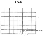
- a block structure which is shown in Fig. 18 is formed by collecting subband coefficients (hereinafter referred to as coefficients) corresponding to the same spacial positions which are linked with each other by arrows as shown in Fig. 17 from the image which has been decomposed in subbands. It has already known that there is a correlation between coefficients which are linked with each other by arrows in Fig.17 excepting the highest frequency subbands.
- coefficients subband coefficients
- the whole relation of the coefficients which are linked with each other by arrows in Fig. 17 is referred to as "trees".
- One coefficient of each of the subbands (LH3, HL3, HH3) having a frequency one level higher than that of one coefficient of the lowest frequency subband (LL3) corresponds thereto (for example, a1, a2 and a3 correspond to a0 in Fig. 17).
- Four coefficients of each of the subbands (LH2, HL2, HH2) having a frequency one level higher than that of each of these coefficients correspond thereto (for example, a10, a11, a12, a13 correspond to a1 in Fig. 17).
- each of the subbands (LH1, HL1, HH1) having a frequency one level higher than that of each of four coefficients correspond thereto.
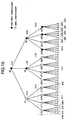
- Trees with respect to coefficient a0 is shown in Fig. 19.
- White circle ⁇ and solid black circle ⁇ in Fig. 19 denote coefficients in each subband.
- the trees in upper area comprise coefficients of the subbands having a lower resolution while the trees in lower area comprise coefficients of the subbands having a higher resolution.
- coefficients having lower resolution are referred to as "parents” and the coefficients having next higher resolution in the same spacial position as designated by arrows are referred to as "children".
- coefficient a0 is a parent for coefficients a1, a2 and a3, which are in turn children for coefficient a0.
- coefficient a1 is a parent for coefficients a10, a11, a12 and a13 and, coefficients a10, a11, a12 and a13 are children for coefficient a1.
- the coefficients are quantized in the block basis.
- Three symbols are assigned to each node of the trees for representing whether the quantization coefficient is zero or non-zero. Definition of the symbol will now be described.
- the coefficient having the lowest frequency among the coefficients in which one coefficient in a tree is zero and the coefficients of its descendants are all zero is referred to as zero-tree-root (ZTR), Since this coefficient and the coefficients having a higher resolution than that of the former coefficient are all zero at this time, it would be unnecessary to code the coefficients of its descendant if ZTR appear an a tree.
- ZTR zero-tree-root
- VZTR valued zero-tree root
- Value If there is any one non-zero coefficient in the descendant, its coefficient is referred to as "Value”.
- White and solid black circles denote the coefficients which the quantizing value is zero and non-zero, respectively in Fig. 19. In this case, the coefficients which require coding are shown in Fig. 20. Since a0 has a quantizing value which is not "zero" in Fig. 20, the symbol Value is assigned to code the quantizing value. Since a1 and its descendants (a10 through a13, a100 through a103 through a133) are all zero, symbol ZTR is assigned to a1 and it is not necessary to code the quantizing value. Since it can be found that the value of a1 is zero due to the fact that a1 is ZTR, it is never necessary to code the information on the descendants of a1.
- VZTR is assigned for coding only the quantizing value of a2.
- a3 has a quantizing value which is not zero and there are some descendants which have a quantizing value which is not zero, symbol Value is assigned for coding the quantizing value.
- VZTR is assigned for a30.
- ZTR is assigned for a31.
- Value is assigned for a32 and a33. Only the quantizing values of the coefficients having the highest frequency (a320 through a333) are coded without assigning a symbol to the coefficients,
- the information to be coded on this block comprises:
- the order of coding of the coefficients does not shift subband by subband, but quantization of each block is conducted, then the symbol information and the coefficient information in the block basis is completely coded and thereafter coding of next block is initiated.
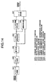
- a reference numeral 1401 denotes a subband decomposing portion for decomposing an image into subbands by means of a two-dimensional decomposing filter
- 1402 denotes a block forming portion for forming a block by collecting coefficients having a parent-child relationship from the decomposed subbands as shown in Fig. 18,
- 1403 denotes a quantizing portion for quantizing the coefficients in the block basis
- 1404 denotes a symbol information determining portion for determining the symbol which is shown in Fig.
- Fig. 22 is a flow chart showing a series of the operations.
- a reference numeral 1501 denotes a data separating portion for separating coded data into symbol information and coefficient information for each one
- 1502 denotes a symbol information decoding portion for variable-length decoding symbol information
- 1503 denotes a coefficient decoding portion for decoding the coefficients corresponding to Value and VZTR based upon the decoded symbol information
- 1504 denotes a block data reproducing portion for reproducing all coefficient values for one block based upon the decoded symbol information and coefficient information
- 1505 denotes an inverse quantizing portion for inverse quantizing the quantized coefficients for each block
- 1506 denotes a subband image producing portion for producing the whole subband image by relocating the coefficient values of all blocks to deblocking them
- 1507 denotes a subband synthesizing portion for performing a subband synthesis by means of a two-dimensional synthesizing filter.
- Fig. 23 is a flow chart showing a series of operations.
- the subband coefficients can be efficiently coded and decoded in the block basis by using the above-mentioned image coding and decoding devices.
- reproduced images having different resolutions can be decoded from part of the coded data as shown in Fig. 24 in the conventional subband coding technique in which information on one subband is coded and then the information on the subband having the next higher resolution is coded. If for example, the information on only LL3 is decoded from the coded data, the whole image could be reproduced at the lowest resolution.
- the whole image can be reproduced at a resolution which is higher than the case of decoding of only LL3. If all coded data is decoded, the whole image can be reproduced at the highest resolution.
- Fig. 1 is a block diagram showing a first embodiment of the coding device of the present invention.
- a reference numeral 101 denotes a subband decomposing portion
- 102 denotes a block forming portion
- 103 denotes a quantizing portion
- 104 denotes a symbol information determining portion
- 105 denotes a symbol information coding portion
- 106 denotes a coefficient coding portion.
- These portions 101, 102, 103, 104, 105 and 106 are identical in structure with those 1401, 1402, 1403, 1404, 1405 and 1406, respectively, which are shown in Fig. 14.
- an image is decomposed into subbands, which are divided into blocks as shown in Fig. 18.
- the subband coefficients are quantized for each block.
- Quantization is conducted in the block basis although all blocks may be quantized in the same quantization stepsize in a special case.
- the symbols and the quantization coefficients in Fig. 18 which are produced by the prior art are divided and relocated in each subband so that subband images are produced again.
- coding of the symbol information and coefficient information is conducted in order from the subband having a lower resolution.
- a reference numeral 108 in Fig. 1 denotes the symbol information relocating portion which relocates the symbol information which is prepared for each block by the prior art for each subband.
- One block of the blocked subband image which is produced by the prior art in Fig. 18 corresponds to the block in a part (a) of Fig. 3.
- the portion 108 in Fig. 1 conducts the relocation of the symbol from the part (a) to a part (b) of Fig. 3 for each block for producing a new subband image to output it to the memory 110.
- a reference numeral 109 in Fig. 1 denotes a coefficient relocating portion which relocates the coefficient information which is quantized for each block by the prior art for each subband.
- One block of the blocked subband image which is produced by the prior art in Fig. 18 corresponds to the block in the part (a) of Fig. 3.
- the portion 109 in Fig. 1 conducts the relocation of the coefficient information from the part (a) to a part (c) of Fig. 3 for each block for producing a new subband image to output it to the memory 111.
- the symbol of the SKIP is written in lieu of the coefficient value as mentioned above and is not coded when coding is conducted.
- Relocation of the symbols from the part (a) to (b) of Fig. 3 and the relocation of the coefficient values from the part (a) to (c) of Fig. 3 may be conducted by overwriting the relocated symbols and coefficient values into a memory in which the symbols and coefficient values are collected for each block which is shown in Fig. 18 without using the memories 110 and 111 in Fig. 1 and by conducting the subsequent processing by the operation of addresses corresponding to the predetermined positions in memories 110 and 111.
- a reference numeral 107 in Fig. 1 denotes the coded data integrating portion for collectively arranging the symbol information and coefficient information for each subband, which is stored in the memories 110 and 111.
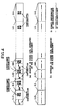
- the method of integrating the symbol information and coefficient information includes two methods which are shown in a part (a) and (b) of Fig. 4.
- the part (a) of Fig. 4 shows an example of contents of the coded data when the symbol information and the coefficient information is collectively arranged for each subband.
- the symbol information and coefficient information is consecutively input starting from that in the subband having the lowest frequency to the subband having higher frequency.
- the coefficient information of one subband is written into the coded data.
- the symbol information of one subband having a frequency which is higher by one level is written into the coded data. Such an operation is repeated until the subband having the highest frequency.
- the part (b) of Fig. 4 shows another example of the contents of the coded data when the symbol information and coefficient information is collectively arranged for each subband.
- the coded data integrating portion firstly one set of the symbol information corresponding to one coefficient and one-coefficient information corresponding to this symbol information is written into the coded data and then similarly one set of symbol information of one coefficient and the coding information corresponding thereto is written into the coded data. This operation is repeated until the subband having the highest frequency. Since there is no coefficient information for the coefficients corresponding to ZTR and SKIP at this time, there is no input so that symbol information is successively input. Since no symbol information exists for the subbands having the highest frequency (HL1, LH1, HH1) as mentioned in the description of the prior art, only the coefficient information is coded. The coded data of the symbol information and coefficient information in the part (b) of Fig. 4 will be shown. S denotes symbol information and C denotes coefficient information.
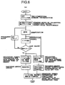
- a part (a) of Fig. 6 is a flow chart showing one example of operation of the image coding device in Fig. 1.
- a part (b) of Fig. 6 is a flow chart for preparing coded data in the part (a) of Fig. 4.
- a part (c) of Fig. 6 is a flow chart for preparing coded data in the part (b) of Fig. 4.
- scalability can be provided to the coded data by producing the coded data in order starting from the subband having lower resolution to the subband having higher solution by the relocation of the symbol information and coefficient information in the coding device in the first embodiment of the present invention.
- Fig. 2 shows a first embodiment of the decoding device of the present invention for decoding the coded data which is prepared by the coding device of the first embodiment of the present invention.
- the coded data Prior to the inverse quantization in the prior art which the coded data is decoded for reproducing the blocked subband images, which are inverse quantized for each block, deblocked them to produce subband images, synthesized to provide a reproduced image, the symbol information and coefficient information is separated and decoded from the coded data and the decoded data is relocated for each subband for producing the whole of subband image and then an additional processing of blocking for inverse quantization is conducted.
- a reference numeral 201 in Fig. 2 denotes a coded data separating portion for separating the coded data into the symbol information and coefficient information to output the resultant information into the symbol information decoding portion 202 and the coefficient decoding portion 203.
- the coded data of, for example the part (a) of Fig. 4 is input, a boundary between the coded symbol information of one subband and the coded coefficient information of one subband corresponding to the symbol information is detected and the symbol and coefficient information is output to the symbol information decoding portion and coefficient decoding portions, respectively.
- a reference numeral 208 denotes a memory for storing therein the symbol information which has been variable-length decoded by the symbol information decoding portion 202 to position corresponding to that on the subband images as shown in the part (b) of Fig. 3.
- a reference numeral 209 denotes a memory for storing therein the coefficient information which has been variable-length decoded by the coefficient decoding portion 203 to position corresponding to that on the subband images as shown in the part (c) of Fig. 3. Since no coefficient having a parent-child relationship, which is higher in resolution exists when the symbol of the corresponding tree is ZTR or SKIP, "0" is written in the memory 209 and no coefficient value is overwritten thereon similarly to the coding device.
- the operation in the decoding device is different from that in the coding device only in that "0" is written in the memory in lieu of "SKIP" in the coding device.
- the coefficient having a parent-child relationship between the subbands are collected by the block forming portion 204 and based upon the coefficients stored in the memory 209 for forming blocks which are shown in the part (a) of Fig. 3.
- the quantized coefficients are inverse quantized for each block by the inverse quantizing portion 205 and the coefficient values of all blocks are relocated by the subband image producing portion 206 for deblocking to produce the whole of the subband images.
- a reproduced image can be obtained by synthesizing the subbands by the subband synthesizing portion 207 using a two dimensional synthesizing filter.
- the symbol information decoding portion 202, coefficient decoding portion 203, inverse quantizing portion 205, subband image producing portion 206, subband synthesizing portion 207 and the block forming portion 204 are identical in structure with the portions 1502, 1503, 1505, 1506, 1507 which are shown in Fig. 15 and the portion 104 shown in Fig. 1, respectively.
- a flow chart showing a series of operations is shown in Fig. 7.
- the coded data having scalability can be decoded in the decoding device of the first embodiment of the present invention.
- Fig. 10 shows another example in which the coding device of the first embodiment of the present invention is implemented.
- the difference between the devices which are shown in Figs. 10 and 1 resides in that a set forming portion 1005 and a set coding portion 1006 are incorporated in lieu of the symbol information coding portion 105, coefficient coding portion 106 and coded data integrating portion 107.
- the symbol information and the coefficient information is independently variable-length coded and arranged in the above-mentioned coding device of the first embodiment, the symbol information and coefficient information is variable-length coded after the set of the symbol and coefficient information in the present example has been formed.
- a set of one item of symbol information and coefficient information corresponding to this symbol information is prepared by the set forming portion 1005. Since no symbol information exist in the subbands having the highest frequency (HL1, LH1, HH1), the coefficient information is treated one item by one item. If only symbol information exists in the subbands having a frequency excepting the highest frequency and no corresponding coefficient information exists (ZTR), only symbol information is treated. Now, an example of sets of symbol information and coefficient information is shown. S denotes the symbol information, C denotes coefficient information, parentheses denote sets.
- the set coding portion 1006 is adapted to variable-length codes the sets of symbol information and coefficient information which are formed by the set forming portion 1005.
- the specific variable-length coding method may include two-dimensional Huffman coding of the symbol information and the coefficient information, variable-length coding in which the same symbols are consecutive if only symbol information is consecutive and one-dimensional Huffman coding if only coefficients are consecutive.
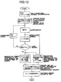
- a flow chart of a series of operations is shown in Fig. 12.
- the symbol information and coefficient information are relocated in another coding device of the first embodiment of the present invention. Accordingly, it can be formed the coded data to have the scalability by forming from lower resolution subbands to higher resolution subbands in order.
- Fig. 11 shows another example in which the decoding device of the first embodiment of the present invention is implemented.
- a set decoding portion 1101 and a set separating portion 1102 are incorporated in lieu of the coded data separating portion 201, the symbol information decoding portion 202, and coefficient decoding portion 203.
- the symbol information and the coefficient information which has been independently coded is variable-length coded after the separation thereof in the decoding device of the above-mentioned embodiment, the set of the symbol information and coefficient information is variable-length coded and thereafter is separated into the symbol information and coefficient information in the present case.
- coded data in which the set of the symbol information and the coefficient information which is variable-length coded by the coding device shown in Fig. 10 is variable-length decoded. Since no symbol information exists in the subbands having the highest frequency (HL1, LH1, HH1) similarly to the description of the coding in this case, only the coefficient information is decoded.
- the set of the symbol information and the coefficient information which has been decoded in the set decoding portion 1101 is separated into the symbol information and coefficient information by the set separating portion 1102 so that it is output to the memories 1108 and 1109.
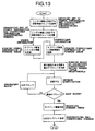
- a flow chart showing a series of these operations is shown in Fig. 13.
- coded data having scalability can be decoded by another decoding device of the first embodiment of the present invention.
- Fig. 8 shows a second embodiment of the decoding device of the present invention. Coding device is identical with that of the first embodiment.
- a data interpolating portion 810 is added in the device shown in Fig. 8. If the coded data which has been prepared by image coding device is not completely input to the image decoding device or if all the coded data which has been transmitted can not decoded due to low processing speed of the image decoding device, the last half of the coded data may not be input to the image decoding device.
- Fig. 5 shows the contents of the memories 808 and 809 in Fig. 8 when the leading portion of the coded data having scalability which is input to the image decoding device. Since the coded data which has been prepared by the image coding device of the first embodiment has the hierarchical structure from the information of the subbands having lower frequency to the information of the subbands having higher frequency, the symbol information and the coefficient information which has been decoded from the discontinued coded data exists as represented by hatched area in a part (a) of Fig. 5.
- blanks denote the coefficients in which the information on the coded data does not exist so that the information can not be decoded.
- the data interpolating portion 810 in Fig. 8 substitutes the coefficients of the blanks in the part (a) of Fig. 5 for "0" to interpolate all coefficients of the subband image. Since data on only part of the HL2 in the second hierarchical level of the subband exists in this case, the reproduced image area corresponding to this part has a higher resolution in a horizontal direction.
- the part (a) of Fig. 5 shows a case the coded data is discontinued in the course of the subband HL2.
- half-toned upper half area is an area having a relatively higher resolution in which coded data up to LL3, HL3, LH3, HH3 and HL2 exists in each block when blocking is conducted while lower half area is an area having a relatively lower resolution in which coded data up to LL3, HL3, LH3 and HH3 exists in each block when blocking is conducted.
- the subsequent operation can be proceeded as is similarly to the decoding device of the above-mentioned first embodiment.
- a reproduced image when only part of the coded data is decoded in such a manner is shown in a part (c) of Fig. 5.
- the part (c) of Fig. 5 is relevant to the part (a) of Fig. 5. Images having higher resolution can be obtained in upper half of the screen while images having a resolution which is one level lower in a vertical direction than that of upper half screen is obtained in the lower half of the screen.
- a flow chart showing a series of the operations is shown in Fig. 9.
- the whole of the image can be decoded from part of the coded data having scalability by the decoding device of the second embodiment of the present invention.
- Coded data having a desired quantity of data can be reproduced substantially consecutively from the leading portion of the coded data when only part of the coded data is decoded. In other words, an image can be reproduce even if decoding is terminated in a desired position of the coded data.
- the reproduced image of the whole image can be obtained from part of the coded data by providing the coded data with scalability in accordance with the present invention.
Landscapes
- Engineering & Computer Science (AREA)
- Multimedia (AREA)
- Signal Processing (AREA)
- Compression Or Coding Systems Of Tv Signals (AREA)
- Compression Of Band Width Or Redundancy In Fax (AREA)
Applications Claiming Priority (3)
| Application Number | Priority Date | Filing Date | Title |
|---|---|---|---|
| JP2230897 | 1997-02-05 | ||
| JP2230897A JP3213561B2 (ja) | 1997-02-05 | 1997-02-05 | 画像符号化装置及び画像復号装置 |
| PCT/JP1998/000359 WO1998035502A1 (fr) | 1997-02-05 | 1998-01-29 | Un codeur et un decodeur d'image |
Publications (3)
| Publication Number | Publication Date |
|---|---|
| EP0961494A1 true EP0961494A1 (fr) | 1999-12-01 |
| EP0961494A4 EP0961494A4 (fr) | 2001-09-05 |
| EP0961494B1 EP0961494B1 (fr) | 2004-04-07 |
Family
ID=12079122
Family Applications (1)
| Application Number | Title | Priority Date | Filing Date |
|---|---|---|---|
| EP98901034A Expired - Lifetime EP0961494B1 (fr) | 1997-02-05 | 1998-01-29 | Un codeur et un decodeur d'image |
Country Status (6)
| Country | Link |
|---|---|
| US (1) | US6529636B1 (fr) |
| EP (1) | EP0961494B1 (fr) |
| JP (1) | JP3213561B2 (fr) |
| DE (1) | DE69823011T2 (fr) |
| ES (1) | ES2219867T3 (fr) |
| WO (1) | WO1998035502A1 (fr) |
Cited By (3)
| Publication number | Priority date | Publication date | Assignee | Title |
|---|---|---|---|---|
| EP1047271A3 (fr) * | 1999-04-19 | 2000-11-15 | Sharp Kabushiki Kaisha | Compression et décompression d'images de référence dans un décodeur vidéo |
| WO2003090471A1 (fr) * | 2002-04-19 | 2003-10-30 | Qinetiq Limited | Compression de donnees pour images colorees par transformation en ondelettes |
| AU2011308154B2 (en) * | 2010-09-30 | 2015-10-08 | Samsung Electronics Co., Ltd. | Video encoding method for encoding hierarchical-structure symbols and a device therefor, and video decoding method for decoding hierarchical-structure symbols and a device therefor |
Families Citing this family (8)
| Publication number | Priority date | Publication date | Assignee | Title |
|---|---|---|---|---|
| JP3224514B2 (ja) * | 1996-08-21 | 2001-10-29 | シャープ株式会社 | 動画像符号化装置および動画像復号装置 |
| FR2792432B1 (fr) * | 1999-04-15 | 2001-07-13 | Canon Kk | Dispositif et procede de transformation de signal numerique |
| CN1197253C (zh) | 1999-04-15 | 2005-04-13 | 株式会社理光 | 数据高速压缩伸展方法及其装置 |
| FR2792433A1 (fr) * | 1999-04-15 | 2000-10-20 | Canon Kk | Dispositif et procede de transformation de signal numerique |
| KR100783396B1 (ko) * | 2001-04-19 | 2007-12-10 | 엘지전자 주식회사 | 부호기의 서브밴드 분할을 이용한 시공간 스케일러빌러티방법 |
| EP2135933B1 (fr) | 2008-06-20 | 2013-04-03 | The Procter and Gamble Company | Composition de lavage |
| JP6188651B2 (ja) * | 2014-07-25 | 2017-08-30 | 京セラドキュメントソリューションズ株式会社 | 画像処理装置および画像処理プログラム |
| CN109344629B (zh) * | 2018-09-19 | 2021-04-23 | 湖北工程学院 | 图像加密隐藏方法及装置、图像解密方法及装置 |
Family Cites Families (11)
| Publication number | Priority date | Publication date | Assignee | Title |
|---|---|---|---|---|
| JP3158458B2 (ja) | 1991-01-31 | 2001-04-23 | 日本電気株式会社 | 階層表現された信号の符号化方式 |
| US5315670A (en) * | 1991-11-12 | 1994-05-24 | General Electric Company | Digital data compression system including zerotree coefficient coding |
| US5412741A (en) * | 1993-01-22 | 1995-05-02 | David Sarnoff Research Center, Inc. | Apparatus and method for compressing information |
| JP3050736B2 (ja) | 1993-12-13 | 2000-06-12 | シャープ株式会社 | 動画像符号化装置 |
| JP3224465B2 (ja) | 1993-12-22 | 2001-10-29 | シャープ株式会社 | 画像符号化装置 |
| JP3356516B2 (ja) | 1993-12-28 | 2002-12-16 | シャープ株式会社 | 動画像符号化装置 |
| JP3086396B2 (ja) | 1995-03-10 | 2000-09-11 | シャープ株式会社 | 画像符号化装置及び画像復号装置 |
| US6023301A (en) | 1995-07-14 | 2000-02-08 | Sharp Kabushiki Kaisha | Video coding device and video decoding device |
| JP3249729B2 (ja) | 1995-10-24 | 2002-01-21 | シャープ株式会社 | 画像符号化装置及び画像復号装置 |
| US6483946B1 (en) * | 1995-10-25 | 2002-11-19 | Sarnoff Corporation | Apparatus and method for encoding zerotrees generated by a wavelet-based coding technique |
| US6157746A (en) * | 1997-02-12 | 2000-12-05 | Sarnoff Corporation | Apparatus and method for encoding wavelet trees generated by a wavelet-based coding method |
-
1997
- 1997-02-05 JP JP2230897A patent/JP3213561B2/ja not_active Expired - Lifetime
-
1998
- 1998-01-29 EP EP98901034A patent/EP0961494B1/fr not_active Expired - Lifetime
- 1998-01-29 US US09/355,839 patent/US6529636B1/en not_active Expired - Fee Related
- 1998-01-29 ES ES98901034T patent/ES2219867T3/es not_active Expired - Lifetime
- 1998-01-29 DE DE1998623011 patent/DE69823011T2/de not_active Expired - Lifetime
- 1998-01-29 WO PCT/JP1998/000359 patent/WO1998035502A1/fr not_active Ceased
Cited By (5)
| Publication number | Priority date | Publication date | Assignee | Title |
|---|---|---|---|---|
| US6272180B1 (en) | 1997-11-21 | 2001-08-07 | Sharp Laboratories Of America, Inc. | Compression and decompression of reference frames in a video decoder |
| EP1047271A3 (fr) * | 1999-04-19 | 2000-11-15 | Sharp Kabushiki Kaisha | Compression et décompression d'images de référence dans un décodeur vidéo |
| WO2003090471A1 (fr) * | 2002-04-19 | 2003-10-30 | Qinetiq Limited | Compression de donnees pour images colorees par transformation en ondelettes |
| US7512277B2 (en) | 2002-04-19 | 2009-03-31 | Qinetio Limited | Data compression for colour images using wavelet transform |
| AU2011308154B2 (en) * | 2010-09-30 | 2015-10-08 | Samsung Electronics Co., Ltd. | Video encoding method for encoding hierarchical-structure symbols and a device therefor, and video decoding method for decoding hierarchical-structure symbols and a device therefor |
Also Published As
| Publication number | Publication date |
|---|---|
| DE69823011T2 (de) | 2005-03-31 |
| EP0961494A4 (fr) | 2001-09-05 |
| DE69823011D1 (de) | 2004-05-13 |
| ES2219867T3 (es) | 2004-12-01 |
| JPH10224788A (ja) | 1998-08-21 |
| EP0961494B1 (fr) | 2004-04-07 |
| JP3213561B2 (ja) | 2001-10-02 |
| WO1998035502A1 (fr) | 1998-08-13 |
| US6529636B1 (en) | 2003-03-04 |
Similar Documents
| Publication | Publication Date | Title |
|---|---|---|
| US6466698B1 (en) | Efficient embedded image and video compression system using lifted wavelets | |
| US6101279A (en) | Image compression system using block transforms and tree-type coefficient truncation | |
| US5321776A (en) | Data compression system including successive approximation quantizer | |
| US6917716B2 (en) | Image processing apparatus and method and storage medium | |
| JP3853758B2 (ja) | 画像符号化装置 | |
| US5315670A (en) | Digital data compression system including zerotree coefficient coding | |
| KR100524566B1 (ko) | 이미지 처리 장치 및 방법 | |
| US6266450B1 (en) | Encoding method and apparatus | |
| EP0961494B1 (fr) | Un codeur et un decodeur d'image | |
| CA2298687A1 (fr) | Codage et decodage de signaux | |
| EP1466483A1 (fr) | Separation de couches correspondant a des codeurs et interpolation permettant la compression de documents composes | |
| GB2258781A (en) | Data compression | |
| EP0905651A2 (fr) | Procédé et appareil de traitement d'images | |
| JP2000341693A (ja) | デジタル信号変換方法及び装置 | |
| US6606416B1 (en) | Encoding method and apparatus for representing a digital image | |
| Shi et al. | Remote sensing image compression based on adaptive directional wavelet transform with content-dependent binary tree codec | |
| US8588539B2 (en) | Methods and devices for filtering and coding a digital signal | |
| US20050135690A1 (en) | Run length coding and decoding | |
| Kutil | Significance map-based adaptive wavelet zerotree codec (SMAWZ) | |
| JPH06178280A (ja) | 画像情報符号化装置及び画像情報復号化装置 | |
| AU725719B2 (en) | A method of digital image compression | |
| CA2400496C (fr) | Procede de decodage d'image | |
| AU727894B2 (en) | An encoding method and apparatus | |
| AU727434B2 (en) | Method and apparatus for decoding | |
| US20050135692A1 (en) | Zero coding |
Legal Events
| Date | Code | Title | Description |
|---|---|---|---|
| PUAI | Public reference made under article 153(3) epc to a published international application that has entered the european phase |
Free format text: ORIGINAL CODE: 0009012 |
|
| 17P | Request for examination filed |
Effective date: 19990827 |
|
| AK | Designated contracting states |
Kind code of ref document: A1 Designated state(s): DE ES FR GB IT NL |
|
| K1C3 | Correction of patent application (complete document) published |
Effective date: 19991201 |
|
| A4 | Supplementary search report drawn up and despatched |
Effective date: 20010724 |
|
| AK | Designated contracting states |
Kind code of ref document: A4 Designated state(s): DE ES FR GB IT NL |
|
| GRAP | Despatch of communication of intention to grant a patent |
Free format text: ORIGINAL CODE: EPIDOSNIGR1 |
|
| GRAS | Grant fee paid |
Free format text: ORIGINAL CODE: EPIDOSNIGR3 |
|
| GRAA | (expected) grant |
Free format text: ORIGINAL CODE: 0009210 |
|
| AK | Designated contracting states |
Kind code of ref document: B1 Designated state(s): DE ES FR GB IT NL |
|
| REG | Reference to a national code |
Ref country code: GB Ref legal event code: FG4D |
|
| REF | Corresponds to: |
Ref document number: 69823011 Country of ref document: DE Date of ref document: 20040513 Kind code of ref document: P |
|
| REG | Reference to a national code |
Ref country code: ES Ref legal event code: FG2A Ref document number: 2219867 Country of ref document: ES Kind code of ref document: T3 |
|
| ET | Fr: translation filed | ||
| PLBE | No opposition filed within time limit |
Free format text: ORIGINAL CODE: 0009261 |
|
| STAA | Information on the status of an ep patent application or granted ep patent |
Free format text: STATUS: NO OPPOSITION FILED WITHIN TIME LIMIT |
|
| 26N | No opposition filed |
Effective date: 20050110 |
|
| PGFP | Annual fee paid to national office [announced via postgrant information from national office to epo] |
Ref country code: FR Payment date: 20120202 Year of fee payment: 15 |
|
| PGFP | Annual fee paid to national office [announced via postgrant information from national office to epo] |
Ref country code: DE Payment date: 20120125 Year of fee payment: 15 |
|
| PGFP | Annual fee paid to national office [announced via postgrant information from national office to epo] |
Ref country code: GB Payment date: 20120125 Year of fee payment: 15 Ref country code: IT Payment date: 20120117 Year of fee payment: 15 |
|
| PGFP | Annual fee paid to national office [announced via postgrant information from national office to epo] |
Ref country code: NL Payment date: 20120125 Year of fee payment: 15 |
|
| PGFP | Annual fee paid to national office [announced via postgrant information from national office to epo] |
Ref country code: ES Payment date: 20120127 Year of fee payment: 15 |
|
| REG | Reference to a national code |
Ref country code: NL Ref legal event code: V1 Effective date: 20130801 |
|
| GBPC | Gb: european patent ceased through non-payment of renewal fee |
Effective date: 20130129 |
|
| REG | Reference to a national code |
Ref country code: FR Ref legal event code: ST Effective date: 20130930 |
|
| PG25 | Lapsed in a contracting state [announced via postgrant information from national office to epo] |
Ref country code: NL Free format text: LAPSE BECAUSE OF NON-PAYMENT OF DUE FEES Effective date: 20130801 Ref country code: DE Free format text: LAPSE BECAUSE OF NON-PAYMENT OF DUE FEES Effective date: 20130801 |
|
| REG | Reference to a national code |
Ref country code: DE Ref legal event code: R119 Ref document number: 69823011 Country of ref document: DE Effective date: 20130801 |
|
| PG25 | Lapsed in a contracting state [announced via postgrant information from national office to epo] |
Ref country code: FR Free format text: LAPSE BECAUSE OF NON-PAYMENT OF DUE FEES Effective date: 20130131 Ref country code: GB Free format text: LAPSE BECAUSE OF NON-PAYMENT OF DUE FEES Effective date: 20130129 |
|
| PG25 | Lapsed in a contracting state [announced via postgrant information from national office to epo] |
Ref country code: IT Free format text: LAPSE BECAUSE OF NON-PAYMENT OF DUE FEES Effective date: 20130129 |
|
| REG | Reference to a national code |
Ref country code: ES Ref legal event code: FD2A Effective date: 20140321 |
|
| PG25 | Lapsed in a contracting state [announced via postgrant information from national office to epo] |
Ref country code: ES Free format text: LAPSE BECAUSE OF NON-PAYMENT OF DUE FEES Effective date: 20130130 |