EP0961521A2 - Procédé et dispositif pour commuter des signaux utilisant une signal d'état de groupe imbriqué - Google Patents
Procédé et dispositif pour commuter des signaux utilisant une signal d'état de groupe imbriqué Download PDFInfo
- Publication number
- EP0961521A2 EP0961521A2 EP99303847A EP99303847A EP0961521A2 EP 0961521 A2 EP0961521 A2 EP 0961521A2 EP 99303847 A EP99303847 A EP 99303847A EP 99303847 A EP99303847 A EP 99303847A EP 0961521 A2 EP0961521 A2 EP 0961521A2
- Authority
- EP
- European Patent Office
- Prior art keywords
- group
- signal
- signal status
- individual signals
- status
- Prior art date
- Legal status (The legal status is an assumption and is not a legal conclusion. Google has not performed a legal analysis and makes no representation as to the accuracy of the status listed.)
- Withdrawn
Links
- 238000000034 method Methods 0.000 title claims description 15
- 230000005540 biological transmission Effects 0.000 claims abstract description 27
- 239000004744 fabric Substances 0.000 claims abstract description 16
- 239000002131 composite material Substances 0.000 claims abstract description 15
- 238000012544 monitoring process Methods 0.000 claims description 9
- RGNPBRKPHBKNKX-UHFFFAOYSA-N hexaflumuron Chemical compound C1=C(Cl)C(OC(F)(F)C(F)F)=C(Cl)C=C1NC(=O)NC(=O)C1=C(F)C=CC=C1F RGNPBRKPHBKNKX-UHFFFAOYSA-N 0.000 description 10
- 230000000694 effects Effects 0.000 description 5
- 238000003780 insertion Methods 0.000 description 5
- 230000037431 insertion Effects 0.000 description 5
- 238000012545 processing Methods 0.000 description 5
- 238000010586 diagram Methods 0.000 description 4
- 230000001934 delay Effects 0.000 description 3
- 230000001360 synchronised effect Effects 0.000 description 3
- 238000012935 Averaging Methods 0.000 description 2
- 238000013459 approach Methods 0.000 description 2
- 230000008901 benefit Effects 0.000 description 2
- 239000000203 mixture Substances 0.000 description 2
- 230000001902 propagating effect Effects 0.000 description 2
- 238000009877 rendering Methods 0.000 description 2
- 230000002457 bidirectional effect Effects 0.000 description 1
- 239000000470 constituent Substances 0.000 description 1
- 238000009795 derivation Methods 0.000 description 1
- 230000009977 dual effect Effects 0.000 description 1
- 238000002955 isolation Methods 0.000 description 1
- 230000003287 optical effect Effects 0.000 description 1
- 230000002093 peripheral effect Effects 0.000 description 1
- 230000000644 propagated effect Effects 0.000 description 1
- 230000011218 segmentation Effects 0.000 description 1
- 230000008054 signal transmission Effects 0.000 description 1
- 238000012360 testing method Methods 0.000 description 1
Images


Classifications
-
- H—ELECTRICITY
- H04—ELECTRIC COMMUNICATION TECHNIQUE
- H04L—TRANSMISSION OF DIGITAL INFORMATION, e.g. TELEGRAPHIC COMMUNICATION
- H04L49/00—Packet switching elements
- H04L49/25—Routing or path finding in a switch fabric
- H04L49/256—Routing or path finding in ATM switching fabrics
- H04L49/258—Grouping
-
- H—ELECTRICITY
- H04—ELECTRIC COMMUNICATION TECHNIQUE
- H04J—MULTIPLEX COMMUNICATION
- H04J3/00—Time-division multiplex systems
- H04J3/16—Time-division multiplex systems in which the time allocation to individual channels within a transmission cycle is variable, e.g. to accommodate varying complexity of signals, to vary number of channels transmitted
- H04J3/1605—Fixed allocated frame structures
- H04J3/1611—Synchronous digital hierarchy [SDH] or SONET
-
- H—ELECTRICITY
- H04—ELECTRIC COMMUNICATION TECHNIQUE
- H04L—TRANSMISSION OF DIGITAL INFORMATION, e.g. TELEGRAPHIC COMMUNICATION
- H04L49/00—Packet switching elements
- H04L49/25—Routing or path finding in a switch fabric
-
- H—ELECTRICITY
- H04—ELECTRIC COMMUNICATION TECHNIQUE
- H04J—MULTIPLEX COMMUNICATION
- H04J2203/00—Aspects of optical multiplex systems other than those covered by H04J14/05 and H04J14/07
- H04J2203/0001—Provisions for broadband connections in integrated services digital network using frames of the Optical Transport Network [OTN] or using synchronous transfer mode [STM], e.g. SONET, SDH
- H04J2203/0003—Switching fabrics, e.g. transport network, control network
- H04J2203/0023—Routing/path finding
-
- H—ELECTRICITY
- H04—ELECTRIC COMMUNICATION TECHNIQUE
- H04L—TRANSMISSION OF DIGITAL INFORMATION, e.g. TELEGRAPHIC COMMUNICATION
- H04L49/00—Packet switching elements
- H04L49/55—Prevention, detection or correction of errors
- H04L49/552—Prevention, detection or correction of errors by ensuring the integrity of packets received through redundant connections
Definitions
- This invention relates generally to digital transmission networks and, more particularly, to embedded control of groups of individual signals transported through digital transmission networks.
- Digital transmission networks such as those based on Synchronous Optical Network/Synchronous Digital Hierarchy (SONET/SDH) standards, are used extensively for transporting broadband communications signals.
- these broadband communications signals may include base rate signals, which are signals having a fundamental rate or structure. Base rate signals are typically combined with other similar base rate signals to create a higher rate and more complex signal.
- base rate signals are signals having a fundamental rate or structure. Base rate signals are typically combined with other similar base rate signals to create a higher rate and more complex signal.
- STS-1 synchronous transport signal
- STS-12 signal may comprise twelve (12) individual STS-1 signals to form a base rate signal group (BRSG) having a composite rate of 622.08 Mbps.
- Complex group switches are known to have a complex switching structure comprising multiple, cascaded selection/switching stages with highly coupled and complex control structures.
- the signal status for each of the individual signals must be resolved to derive a group status at each particular selection/switching stage. This resolution of signal status adds excessive processing overhead which results in undesirable switching delays during signal transmission.
- Out-of-band control techniques which are typically used in prior art group switches to resolve group signal status, can also add further complexity to a group switch.
- each selection stage in a prior art group switch will typically require its own complex control structure to provide group status information.
- the control structures for each selection/switching stage must also be closely coupled to preserve the group status as signals are transported through the stages.
- an overall control structure may also be required to couple the control structures from each individual selection/switching stage along the transmission path. It is also known that the complexity of control increases significantly for configurations having distributed switching elements spanning multiple selection/switching stages.
- Undesirable switching delays and other problems associated with complex control schemes used for group switching are substantially eliminated in accordance with the principles of the invention by computing a group signal status as a function of the signal status of individual signals in a group, embedding the group signal status in each of the individual signals in a group, and independently selecting each of the individual signals in a respective group as a function of the embedded group signal status using an elementary switch fabric.
- each individual signal in the group is independently selected, the individual signals are effectively switched as a composite group through the elementary switch fabric because the selection decisions are based on the same group signal status carried by each of the individual signals in a group. As such, all individual signals in the group are either selected or rejected together as a composite group.
- an independent signal monitor analyzes and reports the signal status of each individual base rate signal to a group status logic element which computes a group signal status for each respective base rate signal group.
- the group signal status is then embedded in the corresponding individual base rate signals by status encoding elements so that the group signal status propagates along with each of the individual base rate signals through the transmission path.
- the group signal status can be extracted from the individual base rate signals by status decoding elements.
- Control logic processes the decoded group signal status and provides the appropriate control signals to the elementary switch fabric to control the selection of the individual base rate signals.
- the elementary switch fabric is an m x n base rate signal selector switch comprising m individual base rate selectors capable of switching n base rate signal groups each having m channels. More specifically, each of the m individual base rate selectors corresponds to one of the m channels and selects a base rate signal for its channel from one of the n base rate signal groups. Because all individual base rate signals within a base rate signal group carry the same group signal status, the individual base rate selectors in the elementary switch fabric can perform the equivalent function of a group switch but without the complexity of prior art arrangements.
- protection switching schemes are typically used in SONET/SDH networks so that communications can be maintained even if there are intermittent faults, outages, or failures on a given transmission path.
- Some examples of the types of network protection switching schemes used in SONET/SDH include: bidirectional line switched ring (BLSR), unidirectional path switched ring (UPSR), dual ring interworking (DRI), and 1 + 1 facility protection to name a few.
- routing In the context of the following detailed description, the terms “routing”, “switching”, “selecting” and “connecting” are used interchangeably to refer to the handling of signals within a transmission path. Additionally, the term “switch fabric” is intended to encompass all the various routing structures known in the art that are used for routing, switching, or connecting signals. Although selector-based switch fabrics are described and shown in the following detailed description and accompanying figures, it should be noted that many types of routing structures having complex hardware and/or software implementations are contemplated for the elementary switch fabric used in the illustrative embodiments described and shown herein. Examples could include an array of hardware selectors, link lists, as well as other implementations known to those skilled in the art.
- base rate signal and base rate signal group (BRSG) are used throughout the detailed description to refer to the types of signals that can be accommodated by the illustrative embodiments of the invention.
- a base rate signal is meant to describe a signal of a fundamental rate or structure,- which could also be combined with other similar base signals (BRS) to create a higher rate and/or more complex signal, such as a base rate signal group (BRSG).
- a base rate signal could be an STS-1 signal having a fundamental rate of 51.84 Mbps
- an STS-12 signal could represent a base rate signal group (BRSG) comprising 12 STS-1 signals with a composite rate of 622.08 Mbps.
- BRSG base rate signal group
- Those skilled in the art will also be able to identify other types of signals which may used in the illustrative embodiments described herein, either because of characteristics relating to rate or structure.
- an analogous fundamental structure may be a physical channel comprising a plurality of virtual paths (VPs).
- FIG. 1 shows in simplified form one illustrative embodiment for embedding status within an input signal according to the principles of the invention.
- an input signal 402 is provided to both a signal monitoring element 410 and to a status encoding element 420.
- signal monitoring element 410 supplies a signal status to status encoding element 420.
- Status encoding element 420 embeds the signal status information provided by signal monitoring element 410 and supplies the data from the input signal along with its embedded signal status information as output signal 402'.
- signal monitoring element 410 and status encoding element 420 can be implemented using techniques well known in the art.
- signal status can be combined with signal data in many different ways, such as by using a telemetry channel, or by modulating the amplitude, frequency, or phase of the signal data, to name a few.
- the input signal 402 includes data while the output signal 402' includes data plus embedded signal status information.
- the additional embedded signal status can be carried in unused overhead bytes.
- Another approach may be to increase the bit rate of transmission, thereby increasing the number of available time slots for transmitting the additional overhead.
- Other known techniques are also contemplated for use in the invention.
- FIG. 2 shows one illustrative embodiment of an apparatus in the context of digital transmission networks according to the principles of the invention.
- a signal interface portion 400 receives a plurality of base rate signal groups 404, 405 each including a plurality of individual base rate signals 402.
- a base rate signal group comprises m base rate signals.
- the first base rate signal group BRSG-1 shown as group 404, comprises m base rate signals BRS 1,1 through BRS 1,m .
- the nth base rate signal group BRSG-n shown as group 405, comprises BRS n,1 through BRS n,m .
- BRSG-2 through BRSG-(n-1) have been omitted.
- Interface portion 400 includes a plurality of signal monitoring elements 410, group status logic blocks 415, and status encoding elements 420 for embedding group signal status information within each of the individual base rate signals 402 in the corresponding groups 404, 405. As shown, individual 402' represent the original base rate signals 402 with the additional embedded signal status added within interface portion 400.
- an independent signal monitor 410 analyzes and reports the signal quality (or other selected attribute) for each base rate signal 402 in a respective group to a common group status logic block 415.
- each group status logic block 415 corresponds to one of the groups.
- GSLB-1 corresponds to BRSG-1
- GSLB-n corresponds to BRSG-n.
- each group status logic block 415 is a logic configuration that blends or computes the quality, or other status information, of each base rate signal in a group.
- each group status logic block 415 creates a common group status for its respective base rate signal group.
- signal monitors 410 shown here as SIG MON 1,1 through SIG MON 1,m , correspond to base rate signals BRS 1,1 through BRS 1,m in group 404.
- Outputs from SIG MON 1,1 through SIG MON 1,m are provided to GSLB-1, which in turn computes a common group status based on the individual signal status reported for each of the base rate signals in that group.
- This common group status is then encoded within each of the base rate signals for the corresponding group 404 using signal encoding elements 420. From this point forward in the transmission path, each of the base rate signals carries forward the status of the group to which they belong.
- each of the base rate signals can also carry its own individual signal status in addition to the common group status.
- Signal switch portion 401 includes a plurality of status decoding elements 431 for decoding group signal status information embedded within each of individual base rate signals 402'.
- Signal switch portion 401 further includes a plurality of elementary base rate selectors 430 which select the appropriate individual base rate signals 402' based on a control signal supplied by a corresponding select logic element 435.
- signal switch portion 401 is an m -channel base-rate signal selector switch having m selectors 430 for selecting the corresponding base rate signals to be provided as output in the m -channel base rate signal group 450. Because group status is embedded within each of the individual base rate signals 402' for a particular group, an elementary base rate switch architecture comprising individual base rate selectors 430 can therefore switch an entire group.
- base rate signals BRS 1,1 through BRS 1,m and BRS n,1 through BRS n,m with their respective embedded group signal statuses shown here as base rate signals 402', are provided as input to signal switch portion 401.
- Status decoding elements 431 receive base rate signals 402', decode the encoded group status information if necessary, and pass the decoded group status information on to select logic element 435.
- Base rate signals 402' are also provided as input to base rate selectors 430.
- Select logic element 435 evaluates the quality and/or status of all inputs associated with the base rate selector 430 under its control and provides an appropriate control signal to enable base rate selector 430 to choose the most appropriate input in accordance with the embedded group signal status and the selection criteria.
- each base rate selector 430 selects a base rate signal corresponding to one channel of the base rate signal group 450 which is provided as output from signal switch portion 401.
- Each base rate selector 430 receives, as input, one base rate signal from each of the groups (BRSG-1 through BRSG-n). Because there are n base rate signal groups, each base rate selector 430 will therefore receive n base rate signal inputs from which to select.
- base rate signals are selected individually by base rate selectors 430 for each of the m channels, in effect, an entire base rate signal group is selected because the selection decision at each base rate selector 430 is based on the same group signal status that is carried by each individual base rate signal in a respective group. Stated otherwise, although each base rate selector 430 independently selects a base rate signal, all base rate selectors 430 will select a base rate signal corresponding to the same base rate signal group. For example, if group 404 is to be selected and switched as output base rate signal group 450 based on the selection criteria, then SELECTOR 1 will select BRS 1,1 , SELECTOR 2 will select BRS 1,2 , and SELECTOR m will select BRS 1,m .
- the individual base rate signals are switched as a composite group so that a switching decision for each of the individual base rate signals, in effect, represents a switching decision for the entire group.
- the complexity of prior art group switches is therefore avoided because an elementary base rate signal architecture having base rate selectors can be used to perform the group switching function.
- group signal status is encoded via status encoding elements 420 and propagates along the transmission path in such a way that the group signal status is extractable and usable at subsequent switching stages if required.
- the illustrative embodiments of the invention would be particularly well-suited for protection switching applications in digital transmission networks because groups of signals could be protection switched between active and standby transmission paths using existing elementary switch fabrics.
- FIGS. 3A and 3B show another embodiment in which multiple levels and types of group signal status may be embedded within the individual base rate signals. It should be noted that many of the features shown in FIGS. 3A and 3B are the same as those depicted in FIG. 2. Specifically, signal switch portion 401 shown in FIG. 3B includes the same types of components and functionality as described for the embodiment shown in FIG. 2. In FIG. 3A, a pre-switch portion 403 has been added in addition to interface portion 400. It should be noted that any number of interface portions 400 or pre-switch portions 403 can be used in accordance with the teachings herein.
- pre-switch portion 403 can be any intermediate stage between interface portion 400 (FIG. 3A) and switch portion 401 (FIG. 3B) where additional status insertion is desired.
- interface portion 400 may represent the fundamental interface point of the system, e.g., an external entry point where input signals are interrogated to derive raw signal status attributes.
- interface portion 400 may represent a subsequent interface point within the system.
- pre-switch portion 403 may then be used for additional status insertion prior to switch portion 401.
- pre-switch portion 403 may be used to monitor the group status that is carried by the individual signals in order to compute or derive a secondary group signal status.
- pre-switch portion 403 includes a number of status monitoring/decoding elements 411, shown here as STATUS MON 1,1 through STATUS MON 1,m and STATUS MON n,1 through STATUS MON n,m , which monitor the individual base rate signals 402' for embedded group signal status that is inserted in a previous stage, e.g., at a previous interface portion 400.
- the status monitoring/decoding elements 411 are used to monitor for group status generated by a previous group status logic block and to decode this group status for processing by another group status logic block in pre-switch portion 403.
- the group status logic block (GSLB) in pre-switch portion 403 could then generate a new group status (e.g., a secondary group status), which could then be encoded along with the previous group status in each of the individual signals via status encoding elements 420 as previously described.
- group status logic block (GSLB) in pre-switch portion 403 could then generate a new group status (e.g., a secondary group status), which could then be encoded along with the previous group status in each of the individual signals via status encoding elements 420 as previously described.
- individual signals 402" now carry status inserted by interface portion 400 and pre-switch portion 403 and are provided as input to switch portion 401.
- an aggregate group status generated through interface portions 400 and pre-switch portions 403 can be carried within each base rate signal in a base rate signal group.
- Group status logic blocks therefore can be used to combine group signal status for a base rate signal group based on either monitored signal status or previously encoded group signal status.
- Pre-switch portion 403 may also be used to insert some form of control to the input signal to bring about a desired result.
- this control insertion could include a command request, e.g., a manual switch request, or a test insertion request, and the like.
- group signal status carried by each individual base rate signal can be used to propagate control information.
- a manual switch request can be embedded within any of the individual base rate signals in a group.
- Each of the other individual base rate signals in that same group could then be updated to carry this same manual switch request.
- the switch request carried by the base rate signals in the group would be appropriately implemented in each of the corresponding selectors 430. In effect, the manual switch request generated for one of the individual base rate signals would result in the appropriate action for the entire group.
- each individual base rate signal can carry multiple layers of signal status, which may include the individual signal status for that particular base rate signal in addition to group signal status provided by group status logic blocks.
- the use of multiple layers of signal status is described in co-pending U.S. patent application entitled “A Control Architecture Using a Multi-Layer Embedded Signal Status Protocol", (Bordogna 2-5-6-5-6), Serial No. , which is herein incorporated by reference. With this capability, multiple selection decisions can be made at any point in the transmission path based on either individual base rate signal status or group signal status, both of which can propagate through the transmission path along with the individual base rate signal.
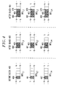
- FIG. 4 illustrates one simplified example of how signal status information can be progressively added to base rate signals in a particular group according to the embodiment shown in FIG. 3A.
- interface portion 400 is meant to represent a subsequent interface point within the system as opposed to a fundamental interface point as previously described.
- base rate signals BRS 1,1 through BRS 1,m in BRSG-1 are shown.
- the base rate signals Prior to entering interface portion 400, the base rate signals could each carry their own individual signal status, shown here 460 for BRS 1,1 , 461 for BRS 1,2 , and 462 for BRS 1,m .
- each of the base rate signals carries its own individual signal status as described above in addition to a group signal status, shown here as 465.
- each base rate signal in BRSG-I includes the same group signal status 465.
- each of the base rate signals is shown to carry its own individual signal status (460, 461, 462), group signal status 465 for BRSG-I, as well as another group signal status 470.
- this other group signal status 470 may represent a group status based on a different selection parameter or may represent a group status corresponding to a larger multiplexed group as described below.
- individual signal status can be advantageously used to reconstruct signal groups without adding any complexity to the control structure.
- the number of groups or composition of groups may change as signals are transported through a network, e.g., as a result of multiplexing/demultiplexing, switching, or cross-connect operations. Consequently, existing groups may be deleted or modified and new groups may be created, thus rendering a previous group signal status as invalid or inaccurate.
- a new group signal status can be easily computed for the newly created or modified group using the individual signal status that is still being carried by each of the individual base rate signals.
- the multiple layers of group signal status can also be advantageously used in a variety of multiplexing applications.
- individual signals may be multiplexed to form a signal group, which may then be multiplexed with other signal groups to form larger signal groups.
- Each individual signal may then carry its own individual signal status as well as multiple levels of group signal status for each signal group to which it belongs.
- a multiplexing operation may multiplex two groups, group A and group B, to form a larger group C. Therefore, an individual signal within group A could carry its own individual signal status, a group status for group A, and a group status for group C.
- the principles of the invention would be particularly applicable and useful for inverse multiplexing applications where higher rate signals are segmented and transported over a number of smaller size tributaries.
- group signal status can be defined with a non-null (e.g., purposeful) value if individual signal status is carried by all individual base rate signals in the group. A subsequent selection would then be based on the non-null group signal status. If group signal status is assigned a null value, a subsequent selection would only then be based on the individual signal status of the base rate signals. In an implementation where base rate signals carry multiple levels of group signal status, selection can be based on any of the multiple levels of group signal status. As expected, this type of implementation may require a more intelligent selector in order to decide which group signal status is to be used.
- group signal status may also be used to support switching decisions based on different criteria.
- group signal status can be based on any type of parameter (e.g., time-based, quality, etc.) and can be implemented in many different ways.
- quality e.g., group signal status could be determined on a worst-link approach, wherein the group signal status for a particular base rate signal group corresponds to the signal status of the individual base rate signal having the worst quality rating or value in the group.
- Group signal status may also be computed using an averaging technique, wherein group signal status is determined by averaging the individual statuses for each of the individual base rate signals in the group.
- group signal status may be computed based on throughput considerations. It may also be desirable to switch for maximum bandwidth through the various links in a network. In such a case, the group signal status would be computed to account for bandwidth requirements.
- the group signal status may be based on only a subset of the individual base rate signals in a particular group, yet the entire group would be switched accordingly.
- a system may use several particular channels to carry specialized data, with loss of this data rendering the entire group unusable regardless of the status of the remainder of the group's signals.
- the group signal status could then be derived based only on these particular channels, but used to effect switching of the entire group.
- an STS-48 signal group may comprise three (3) STS-12 signals and twelve (12) STS-1 signals. Within the STS-48 group, each of the STS-12 signals may be switched as a group using a group signal status derived therefrom.
- teachings of the invention may also be incorporated in fault isolation, identification and/or segmentation applications in which an embedded group signal status is used to manage faults in a multi-span, serial transmission path carrying higher order signal groups.
- any application that could benefit from using embedded control would be able to apply the teachings of the invention described herein. Accordingly, the scope of the invention is limited only by the claims that follow.
Landscapes
- Engineering & Computer Science (AREA)
- Computer Networks & Wireless Communication (AREA)
- Signal Processing (AREA)
- Time-Division Multiplex Systems (AREA)
- Data Exchanges In Wide-Area Networks (AREA)
- Use Of Switch Circuits For Exchanges And Methods Of Control Of Multiplex Exchanges (AREA)
- Compression, Expansion, Code Conversion, And Decoders (AREA)
- Transmission Systems Not Characterized By The Medium Used For Transmission (AREA)
Applications Claiming Priority (2)
| Application Number | Priority Date | Filing Date | Title |
|---|---|---|---|
| US87067 | 1987-08-19 | ||
| US09/087,067 US6301228B1 (en) | 1998-05-29 | 1998-05-29 | Method and apparatus for switching signals using an embedded group signal status |
Publications (2)
| Publication Number | Publication Date |
|---|---|
| EP0961521A2 true EP0961521A2 (fr) | 1999-12-01 |
| EP0961521A3 EP0961521A3 (fr) | 2001-01-10 |
Family
ID=22202924
Family Applications (1)
| Application Number | Title | Priority Date | Filing Date |
|---|---|---|---|
| EP99303847A Withdrawn EP0961521A3 (fr) | 1998-05-29 | 1999-05-18 | Procédé et dispositif pour commuter des signaux utilisant une signal d'état de groupe imbriqué |
Country Status (6)
| Country | Link |
|---|---|
| US (1) | US6301228B1 (fr) |
| EP (1) | EP0961521A3 (fr) |
| JP (1) | JP3476709B2 (fr) |
| CN (1) | CN1237857A (fr) |
| AU (1) | AU745963B2 (fr) |
| CA (1) | CA2266866C (fr) |
Families Citing this family (8)
| Publication number | Priority date | Publication date | Assignee | Title |
|---|---|---|---|---|
| US6693904B1 (en) * | 1998-04-09 | 2004-02-17 | Lucent Technologies Inc. | Trace format for a sliced switch fabric |
| US7315540B2 (en) * | 2002-07-31 | 2008-01-01 | Texas Instruments Incorporated | Random access memory based space time switch architecture |
| US7508752B1 (en) | 2003-05-30 | 2009-03-24 | Cisco Technology, Inc. | Hardware facility switching in cross-connect systems |
| US20060098660A1 (en) * | 2004-11-10 | 2006-05-11 | Rajesh Pal | Mechanism for automatic protection switching and apparatus utilizing same |
| US8660146B2 (en) * | 2008-01-15 | 2014-02-25 | Telefonaktiebolaget Lm Ericsson (Publ) | Telecom multiplexer for variable rate composite bit stream |
| US10165228B2 (en) | 2011-12-22 | 2018-12-25 | Mis Security, Llc | Sensor event assessor training and integration |
| US8902936B2 (en) | 2011-12-22 | 2014-12-02 | Cory J. Stephanson | Sensor event assessor input/output controller |
| CN113054991B (zh) * | 2021-02-02 | 2022-12-20 | 中国电子科技集团公司第二十九研究所 | 开关矩阵的实现方法、开关矩阵、模块及波束合成网络 |
Family Cites Families (14)
| Publication number | Priority date | Publication date | Assignee | Title |
|---|---|---|---|---|
| US4847877A (en) | 1986-11-28 | 1989-07-11 | International Business Machines Corporation | Method and apparatus for detecting a predetermined bit pattern within a serial bit stream |
| US5008882A (en) | 1987-08-17 | 1991-04-16 | California Institute Of Technology | Method and apparatus for eliminating unsuccessful tries in a search tree |
| ES2054909T3 (es) | 1989-03-22 | 1994-08-16 | Siemens Ag | Procedimiento para el control de calidad al menos de dos secciones de transmision de un trayecto de transmision de señales digitales y dispositivo para la realizacion del procedimiento. |
| US5555477A (en) | 1992-04-08 | 1996-09-10 | Hitachi, Ltd. | Optical transmission system constructing method and system |
| US5329520A (en) | 1992-07-17 | 1994-07-12 | Alcatel Network Systems, Inc. | High-speed facility protection in a digital telecommunications system |
| US5465256A (en) | 1993-12-23 | 1995-11-07 | Krone Ag | Telephone cross connect status signal pre-processor |
| JPH0897841A (ja) | 1994-09-29 | 1996-04-12 | Hitachi Ltd | パス切替伝送装置の制御方法及びパス切替伝送装置 |
| JP3376144B2 (ja) | 1994-12-28 | 2003-02-10 | 日本電気株式会社 | 光ネットワーク装置及び光伝送方式 |
| US5636203A (en) | 1995-06-07 | 1997-06-03 | Mci Corporation | Method and system for identifying fault locations in a communications network |
| US5838684A (en) | 1996-02-22 | 1998-11-17 | Fujitsu, Ltd. | Low latency, high clock frequency plesioasynchronous packet-based crossbar switching chip system and method |
| US5793745A (en) | 1996-05-06 | 1998-08-11 | Bell Communications Research, Inc. | Bundled protection switching in a wide area network background of the invention |
| US5838924A (en) | 1996-08-06 | 1998-11-17 | Lucent Technologies Inc | Asynchronous transfer mode (ATM) connection protection switching apparatus and method |
| US5822299A (en) | 1996-10-29 | 1998-10-13 | Nothern Telecom Limited | Path protection in a telecommunications network |
| US6560202B1 (en) | 1998-07-27 | 2003-05-06 | Lucent Technologies Inc. | Control architecture using a multi-layer embedded signal status protocol |
-
1998
- 1998-05-29 US US09/087,067 patent/US6301228B1/en not_active Expired - Lifetime
-
1999
- 1999-03-25 CA CA002266866A patent/CA2266866C/fr not_active Expired - Lifetime
- 1999-05-18 EP EP99303847A patent/EP0961521A3/fr not_active Withdrawn
- 1999-05-27 AU AU32276/99A patent/AU745963B2/en not_active Ceased
- 1999-05-27 CN CN99107086.0A patent/CN1237857A/zh active Pending
- 1999-05-28 JP JP14900199A patent/JP3476709B2/ja not_active Expired - Lifetime
Also Published As
| Publication number | Publication date |
|---|---|
| JP3476709B2 (ja) | 2003-12-10 |
| AU3227699A (en) | 1999-12-09 |
| EP0961521A3 (fr) | 2001-01-10 |
| CN1237857A (zh) | 1999-12-08 |
| US6301228B1 (en) | 2001-10-09 |
| JP2000041271A (ja) | 2000-02-08 |
| CA2266866A1 (fr) | 1999-11-29 |
| AU745963B2 (en) | 2002-04-11 |
| CA2266866C (fr) | 2003-07-22 |
Similar Documents
| Publication | Publication Date | Title |
|---|---|---|
| CA2130067C (fr) | Interfonctionnement des anneaux de systemes de transmission annulaires bidirectionnels a commutation par les lignes | |
| EP0654922B1 (fr) | Système de communication ayant des systèmes de transmission interconnectés et annulaires avec des lignes et des chemins commutés | |
| EP0590872B1 (fr) | Dispositif et méthode pour commutation sélective et tributaire dans un réseau bidirectionnel en anneau | |
| EP0654923B1 (fr) | Système de communication ayant des systèmes de transmission interconnectés et annulaires avec des chemins commutés | |
| US7386012B2 (en) | Multiplex transmission apparatuses, multiplex transmission networks, and operation method therefor | |
| EP0716521B1 (fr) | Réseau de communication à structure en boucle au moyen d'une porteuse optique et noeud reconfigurable pour cette structure | |
| US6560202B1 (en) | Control architecture using a multi-layer embedded signal status protocol | |
| JPH1093600A (ja) | 情報通信方法およびsonet回線交換リング用ノード | |
| JPH06303192A (ja) | 光ネットワ−ク及びその障害回復方式 | |
| US6185021B1 (en) | Cross-connecting optical translator array | |
| US6301228B1 (en) | Method and apparatus for switching signals using an embedded group signal status | |
| US6081503A (en) | Control architecture using an embedded signal status protocol | |
| US7058298B2 (en) | Optical transmission device and optical transmission system | |
| US20030235152A1 (en) | Network system incorporating protection paths in the transmission bandwidth of a virtual concatenation signal | |
| WO1993022859A1 (fr) | Procede et dispositif de configuration d'une interconnexion temporelle-spaciale-temporelle lorsque les besoins en interconnexion changent et leur utilisation | |
| JP3301565B2 (ja) | リング伝送装置 | |
| US20040141532A1 (en) | Multiplexer and usage thereof | |
| JP3466962B2 (ja) | Sdhリングシステム | |
| Takatori et al. | A high performance switch for OC-12 SONET self-healing ring networks | |
| JP3334868B2 (ja) | 同期光伝送装置 |
Legal Events
| Date | Code | Title | Description |
|---|---|---|---|
| PUAI | Public reference made under article 153(3) epc to a published international application that has entered the european phase |
Free format text: ORIGINAL CODE: 0009012 |
|
| AK | Designated contracting states |
Kind code of ref document: A2 Designated state(s): DE FR |
|
| AX | Request for extension of the european patent |
Free format text: AL;LT;LV;MK;RO;SI |
|
| PUAL | Search report despatched |
Free format text: ORIGINAL CODE: 0009013 |
|
| AK | Designated contracting states |
Kind code of ref document: A3 Designated state(s): AT BE CH CY DE DK ES FI FR GB GR IE IT LI LU MC NL PT SE |
|
| AX | Request for extension of the european patent |
Free format text: AL;LT;LV;MK;RO;SI |
|
| 17P | Request for examination filed |
Effective date: 20010628 |
|
| AKX | Designation fees paid |
Free format text: DE FR |
|
| STAA | Information on the status of an ep patent application or granted ep patent |
Free format text: STATUS: THE APPLICATION IS DEEMED TO BE WITHDRAWN |
|
| 18D | Application deemed to be withdrawn |
Effective date: 20060810 |