EP0961675B1 - Verfahren zum schneiden von holzstämmen - Google Patents
Verfahren zum schneiden von holzstämmen Download PDFInfo
- Publication number
- EP0961675B1 EP0961675B1 EP97948099A EP97948099A EP0961675B1 EP 0961675 B1 EP0961675 B1 EP 0961675B1 EP 97948099 A EP97948099 A EP 97948099A EP 97948099 A EP97948099 A EP 97948099A EP 0961675 B1 EP0961675 B1 EP 0961675B1
- Authority
- EP
- European Patent Office
- Prior art keywords
- log
- cuts
- pith
- cut
- twin
- Prior art date
- Legal status (The legal status is an assumption and is not a legal conclusion. Google has not performed a legal analysis and makes no representation as to the accuracy of the status listed.)
- Expired - Lifetime
Links
- 238000005520 cutting process Methods 0.000 title claims abstract description 18
- 238000000034 method Methods 0.000 title claims abstract description 17
- 239000002023 wood Substances 0.000 claims description 8
- 238000007688 edging Methods 0.000 claims description 4
- 238000009966 trimming Methods 0.000 abstract 1
- 238000001035 drying Methods 0.000 description 3
- 238000003825 pressing Methods 0.000 description 3
- 238000011161 development Methods 0.000 description 2
- 230000018109 developmental process Effects 0.000 description 2
- 239000000835 fiber Substances 0.000 description 2
- 239000000463 material Substances 0.000 description 2
- 230000015572 biosynthetic process Effects 0.000 description 1
- 239000003638 chemical reducing agent Substances 0.000 description 1
- 230000000366 juvenile effect Effects 0.000 description 1
- 238000004519 manufacturing process Methods 0.000 description 1
- 238000012544 monitoring process Methods 0.000 description 1
- 239000007858 starting material Substances 0.000 description 1
Images


Classifications
-
- B—PERFORMING OPERATIONS; TRANSPORTING
- B27—WORKING OR PRESERVING WOOD OR SIMILAR MATERIAL; NAILING OR STAPLING MACHINES IN GENERAL
- B27B—SAWS FOR WOOD OR SIMILAR MATERIAL; COMPONENTS OR ACCESSORIES THEREFOR
- B27B1/00—Methods for subdividing trunks or logs essentially involving sawing
-
- Y—GENERAL TAGGING OF NEW TECHNOLOGICAL DEVELOPMENTS; GENERAL TAGGING OF CROSS-SECTIONAL TECHNOLOGIES SPANNING OVER SEVERAL SECTIONS OF THE IPC; TECHNICAL SUBJECTS COVERED BY FORMER USPC CROSS-REFERENCE ART COLLECTIONS [XRACs] AND DIGESTS
- Y10—TECHNICAL SUBJECTS COVERED BY FORMER USPC
- Y10T—TECHNICAL SUBJECTS COVERED BY FORMER US CLASSIFICATION
- Y10T83/00—Cutting
- Y10T83/141—With means to monitor and control operation [e.g., self-regulating means]
- Y10T83/148—Including means to correct the sensed operation
- Y10T83/155—Optimizing product from unique workpiece
Definitions
- the present invention relates to a method of the type as stated in claim 1.
- the method relates to the dividing of logs of wood into parts in order to obtain timber with vertical annual rings.
- the invention has occurred during development work on the method which is described in SE 9100830.
- the log is first divided with at least two parallel longitudinal cuts which are substantially diametrical and parallel to the pith.
- at least one diametrical and plane parallel slab of wood is obtained which in its middle has a part made of the pith of the log.
- a pair of essentially half logs are obtained.
- Further planks with vertical annual rings are obtained out of these through cutting with substantially radial cuts at an angel towards the pith.
- pieces of wood with triangular cross-sections which can be glued together in the longitudinal direction with the triangniar points pointing in opposite directions for adjacent pairs of pieces of wood in order to make a block with an even thickness and straight edges.
- Several blocks can be glued together to form thicker blocks which can be used as starting material for further manufacturing of wooden goods. This method gives an extremely high yield from the log and good quality of the finished timber.
- the cut or cuts which are substantially diametrical and parallel to the pith give plane parallel slabs of wood which in their middles contain the pith of the log.
- the pith part in a log is of bad quality and therefore can not be used in timber. It is therefore cut away.
- the pith part in a log is considerably wider at the base of the log near its root. Therefore previously either a large part of the lower end of the log has been cut off or a large part of the middle of the slab or slabs of timber have been cut away after the initial cross cut sawing.
- An object with the invention is to achieve an even better yield from a log and an even better quality of the timber after dividing into pieces.
- Another object with the invention is to provide a way of working for cutting into pieces which requires so few operations as possible and which preferably can be controlled remotely.
- Yet another object with the invention is to provide a system for dividing logs into pieces which gives low labour costs and/or low investment costs.
- the log is first cut into parts by a band or circular saw with at least two nearly diametrical cuts where the outmost lie symmetrically around the pith of the log.
- Each so obtained wide central plank is divided up through a pith cut so that two radial planks are obtained.
- Each radial plank is edged with the outer side as a reference for lining up and such that its edges become substantially parallel. In this way the influence of that the pith of the log is wider in the root part is avoided and each plank has good quality.
- the outermost part of each side of the log can be cut off with alignment cuts which are parallel with the nearly diametrical cuts. This is done so that the cuts lie so close to the edges as possible at the top end of the log. In this way a later shoulder is obtained which is wider at the root end of the approximately cone shaped blocks obtained on each side of the middle plank.
- Each approximately conical block with the alignment cut is guided further through a twin-bladed saw, the cuts of which slant at 30° towards the base surface of the block, and which cuts essentially radially symmetrically around the pith layer.
- the remaining part can then be turned the other way round and be cut by the same twin-blades saw in the same way.
- the two so obtained planks are edged.
- the log can be guided through two-twin blades saws, one after the other, which lean at 30° in opposite directions. These saws can be displaced a relatively small amount in relationship to each other, but they can also be placed in different saw units so that the log is first completely guided through the first saw and then afterwards sawn in the opposite direction in the other saw.
- the middle plank gives boards of good quality because the pith wood has been cut away.
- a saw line in accordance with the invention in a basic embodiment can be equipped with machines which can be managed by four men. It gives a high yield of timber. Through remote controlling the output in a conventional way via for example TV cameras, the saw line can be handled by as few as two or three men which gives a high productivity of sales value per employee, considerably higher than in systems which were known before the invention.
- the timber 1 is placed by means of a conveying device 1' in a timber feeder 2 wherein a first work station 1 supervised by a person P1 has a saw 3, for example of the band saw type with two or four bands. Alternatively saw blades can be used, but this gives a lower yield of timber.
- each log is sawn in at least two nearly diametrical parallel cuts S1 and S2, where the outmost lie on each side of the pith part of the log in order to produce at least one centre plank 1A containing the pith part 6.
- the number of nearly diametrical cuts depends on the desired thickness of the finally obtained planks. For the sake of simplicity below only the formation of two planks will be described but the skilled person clearly can see how more planks than this can be processed.
- sector cuts S3 and S4 are made parallel to the cuts S1 and S2. All the cuts can be cut with band saws but it is alternatively possible to saw all the cuts with saw blades, or the cuts S1 and S2 with bands and the cuts S3 and S4 with saw blades. It is also possible to only saw the cuts S1 and S2 in the work station 1 and to perform the cutting to length at S3 and S4 at a later opportunity, for example with the outer reducers.
- the log 1 is advantageously laid in the timber feeder 2 so that a possible lifting hook (not shown) is placed upwards or downwards. In this way there is a high likelihood that the pith is caught in such a position that the high quality parts should be able to be obtained in the next machinery 20 during operation II where the sawn apart parts 1A, 2A and 2B are further processed.
- the machinery 20 comprises preferably a rip saw 21.
- the machine 21 can advantageously have two or three laterally movable blades or saw bands. Planks are made first of all from the middle piece 1A.
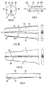
- Fig. 2B shows how log 1A should be cut in order to obtain two planks with parallel sides.
- the flat middle plank 1A is approximately trapezoidal with wider parts down towards the root and the greatest curvature of the pith lying near to the root end.
- the cuts S7 and S8 are made near to the outside of the plank.
- the cuts S9 and S10 are made on each side of the pith part 6 each parallel with its outer side.
- Fig. 2B The log shown in Fig. 2B is drawn with exaggerated curvature. If a log had such a shape in reality then possibly other marking for cross cutting would have to be made in order to obtain the maximal yield. In this case short planks from the root part and longer planks from the top part of the log would be preferable. This can be judged and managed by the person who is monitoring the machinery during operation II.
- the cut out middle plank 1A is preferably divided through a saw blade or a saw band cutting through the pith or on each side of this with straight mutually parallel cuts S5 and S6 in/or extremely close to the pith.
- the remaining parts will then be two approximately trapezoidal planks 4 and 5.
- These planks have their fibre direction parallel with the outerside of the wooden log. Clean cutting with straight cuts S7 and S8 along the outer edges which are inclined in relationship to a central line C1 through the pith can take place either in operation II (not shown) or later in operation II.
- the cut out part or parts of lower quality can be conveyed further for chopping up into chips.
- planks 4 and 5 are then conveyed further with the transporter 25 to the machine III, the way of working of which will be described more closely further on in the description.
- the cutting up of the two essentially semicircular side pieces 2A and 2B is performed.
- One side piece 2A is shown in Fig. 3, the other has in principle the same shape.
- the cut S3 is preferably already sawn in operation I.
- the side piece 2A is laid flat on the cross cutting table.
- the machine 21 performs the cross cuts S11 and S 12 of the outer surfaces 11A and 11B in the lower part according to Fig. 3 with blades 8 and 9 which are adjustable in width.
- the cuts are made here parallel with each other and such that the top end is not or is only lightly affected by the cuts while a guide surface is formed near to the root. This is important in order to lose as little as possible of the timber yield.
- the produced block 11 is conveyed further in a transporter 25 to a machine IV.
- the cut off parts 11A and 11B are conveyed away for example for chopping up (not shown).
- each plank is conveyed to the position L1, where it is fed to the input position L2 for a first sawing in the saw 27.
- planks 4 respectively 5 shall in this case be placed so that a cut S7 respectively S8 can be made parallel with the outerside (the bark side) of the plank so that the fibre direction will be in the same direction as the cut S7 respectively S8 and so close to the outside as possible where the tree has fewer knots.
- the earlier performed cuts S5 respectively S6 can give a straight edge so that guide (not shown) which can be adjusted obliquely set at a chosen angular position against which the straight edge lies, can form a guide for the desired cutting position for S7 respectively S8.
- planks which have been cut along the cuts S7 respectively S8 have the shape which is shown in Fig. 4 and after sawing are in the position L3. Thereafter they are conveyed first from the position L3 to the position L4 and therefrom to a turntable 27 where they are turned. They are then fed to the position L5 in order to be conveyed back in the reversed position L2 in order to once more be conveyed through the saw 27.
- a cut S9 respectively S10 is made at the parts close to the pith and such that at the root end a large amount of the juvenile wood which is of worse quality than the rest is removed.
- the cuts S9 respectively S10 are herewith placed parallel with S7 respectively S8 which means that the guide against which the cut side S7 respectively S8 now rest has been positioned parallel to the direction of sawing.
- the removed part 4B in this case is triangular and can, for example, be chopped up and the remaining plank 4A has become parallelepiped. This is then conveyed from the position L3 to the position L6 in order to be fed out as finished planks from the saw line.
- plank materials 4 and 5 are processed in the same way, suitably after one another.
- the two cut curved parts 11 are transported to a twin band or chain saw for example 30 with two parallel saw blades which preferably incline 30°, which in Fig. 5 have the reference numerals 34 and 35.
- the cuts performed with these saw blades shall be positioned so that a part 36 shaped like a 60° sector of a circle is formed together with a plank 37.
- a block 38 shall remain for further processing.
- the stated number of degrees for the inclination can be selected in another way. Furthermore, it is possible to choose more than two double cuts.
- the part 11 conveyed to the feed device 31 for the saw 30 is fed through the saw 30 with the root end first and in this way is guided by at least one guide surface 39 at the root end with a longitudinal rule (not shown).
- the approximately triangular part 36 is conveyed away via a transporter 40 for drying or further processing and the plank 37 is conveyed via the same transporter 40 or some other to an edging mill (not shown) where it is trimmed in a conventional manner.
- the block 38 is conveyed back to the device 31 and therefrom to the block turner 28 (which turns the block 180° root to top) and then returns to the device 31 for further transport through the band saw which, as shown in Fig. 6, saws up the block into two parts 42 and 43 with essentially a triangular cross section and a plank 45.
- the cuts 34' and 35' are placed substantially each on one side of the part which borders the pith part.
- the plank 45 is transported to the edging mill and trimmed in a conventional manner.
- the parts 42 and 43 with triangular cross sections are transported for drying and/or further processing.
- a guide stop 47 can be moved for example hydraulically in the band saw.
- the guide stop 47 will then be inclined approximately 60° with respect to the base plane.
- the block's 38 obtuse 120° angle will thereby be adapted to lie in line with the intermediate position between the two 30° inclined saw blades 34' and 35'.
- a pressing means 48 for example in the shape of a roller, pressing the block 38 downwardly inclined preferably 60° towards the base plate 50 a positioning in the right position at least at the beginning of the sawing is obtained. After the sawing has begun the pressing means 48 can, however, be removed as the guide stop's 47 vertical guidance takes over.
- the saw 30 can be provided with either two sets of pairs of saws where each pair is inclined 60° in different directions with respect to the base blade and each pair displaced in the direction of sawing so that they do not work against each other.
- the two sets of pairs of saws can be placed so long after each other that the log is sawn in its entirety in two operations.
- the same pair of saws can be adjustable from being inclined in one direction to be inclined in the other direction and the log conveyed twice through the saw. In all these cases two planks are obtained per half log which are conveyed to a conventional edging mill to be trimmed and three triangular parts which are conveyed further for drying and farther processing.
Landscapes
- Life Sciences & Earth Sciences (AREA)
- Engineering & Computer Science (AREA)
- Mechanical Engineering (AREA)
- Wood Science & Technology (AREA)
- Forests & Forestry (AREA)
- Chemical And Physical Treatments For Wood And The Like (AREA)
- Branch Pipes, Bends, And The Like (AREA)
- Light Guides In General And Applications Therefor (AREA)
- Beans For Foods Or Fodder (AREA)
- Perforating, Stamping-Out Or Severing By Means Other Than Cutting (AREA)
- Nonmetal Cutting Devices (AREA)
- Control And Other Processes For Unpacking Of Materials (AREA)
- Apparatuses For Bulk Treatment Of Fruits And Vegetables And Apparatuses For Preparing Feeds (AREA)
- Jellies, Jams, And Syrups (AREA)
Claims (9)
- Verfahren zum Aufteilen eines Baumstamms in Stücke, dadurch gekennzeichnet, dassder Baumstamm zuerst in Stücke durch mindestens zwei nahezu diametrale Schnitte (S1, S2) aufgeteilt wird, wobei das Äußerste im Wesentlichen symmetrisch rund um das Mark des Baumstamms liegt;jede so erreichte Bohle mit der Außenseite als Bezug für die Schneidrichtung randseitig geschnitten wird (S7, S8),zwei Bohlen mit Hilfe von Schnitten (S9, S10) gebildet werden, die in der Nähe des Marks im Wesentlichen parallel zu jeder geschnittenen Außenseite platziert sind.
- Verfahren nach Anspruch 1, gekennzeichnet durch
Querschneiden der äußersten Teile des Baumstamms mit Ausrichtungsschnitten (S3, S4) im Wesentlichen parallel zu den nahezu parallelen Schnitten (S1, S2) vorzugsweise in demselben Vorgang wie das Schneiden in die Teile mit den nahezu diametralen Schnitten. - Verfahren nach Anspruch 1 oder 2, dadurch gekennzeichnet, dass
jeder Block mit Ausrichtungsschnitten (S3, S4) durch mindestens eine Säge mit doppeltem Blatt hindurch transportiert wird, deren Schnitte zu der Basisfläche des Blocks geneigt sind, beispielsweise um 30°, und im Wesentlichen radial symmetrisch um die Position des Marks schneiden. - Verfahren nach Anspruch 3 mit der Verwendung einer Säge mit doppeltem Blatt, dadurch gekennzeichnet, dass nach dem ersten Sägen mit der Säge mit doppeltem Blatt der restliche Teil des Blocks, der nicht unter einem Winkel geschnitten worden ist und einen stumpfen Winkel aufweist, in der anderen Richtung gewendet und mittels derselben Säge mit doppeltem Blatt in der gleichen Richtung geschnitten wird.
- Verfahren nach Anspruch 3, mit der Verwendung von zwei Sägen mit doppeltem Blatt, dadurch gekennzeichnet, dass die beiden Paare der Sägen unter 30° in unterschiedlichen Richtungen zu der Basisfläche des Blocks schräg gestellt sind und entlang der Bewegungsrichtung des Baumstamms während des Sägens verschoben werden.
- Verfahren zum Schneiden von Baumstämmen in Stücke auf einer durchgehenden Sägestraße mit geringer Personalausstattung, dadurch gekennzeichnet, dassa) in einer ersten Arbeitsstation I jeder Baumstamm zu einer ersten Sägeeinrichtung (21) transportiert und dann in Teile mit zwei nahezu diametralen Schnitten geteilt wird, die im Wesentlichen symmetrisch um das Mark des Baumstamms liegen, um eine flache mittlere Bohle und zwei im Querschnitt im Wesentlichen halbkegelige Baumstammteile zu bilden;b) in einer zweiten Arbeitsstation mit einer zweiten Sägeeinrichtung (21)b1) die mittlere Bohle von der ersten zu der zweiten Arbeitsstation transportiert wird und mittels mindestens. eines Schnitts in dem Mark oder in der Nähe des Marks mittels der zweiten Sägeeinrichtung (21) auseinander geschnitten wird, um zwei Bohlen zu bilden, die zu einer dritten Arbeitsstation weiter transportiert werden;b2) alle im Wesentlichen halbkegeligen Teile des Baumstamms von der ersten zu der zweiten Arbeitsstation transportiert und mittels der zweiten Sägeeinrichtung (21) mit zwei parallelen Schnitten entlang der Länge an jeder Seite rechtwinklig zu ihren ebenen Flächen abgesägt werden und die gesägten Teile zu einer vierten Arbeitsstation weiter transportiert werden;c) in einer dritten Arbeitsstation eine dritte Sägeeinrichtung (27) jede Bohle sägt, die durch das Mark in der Nähe des Marks parallel zu ihrer Außenseite geteilt wird, um eine im Wesentlichen quaderförmige fertige Bohle zu bilden;d) in der vierten Arbeitsstation in der vierten Sägeeinrichtung (30) alle im Wesentlichen halbkegelig gestalteten Teile des Baumstamms mit Hilfe von Paaren doppelter, paralleler, im Wesentlichen radialer Schnitte gesägt werden, wobei jedes Paar der Schnitte im Querschnitt durch den Teil des Baumstamms unterschiedliche Neigungen aufweist.
- Verfahren nach Anspruch 6, dadurch gekennzeichnet, dass jede an dem Mark geteilte Bohle parallel zum ihren äußeren Rand entweder in der zweiten oder in der dritten Arbeitsstation getrimmt oder gesägt wird, bevor sie in der Nähe des Marks gesägt wird.
- Verfahren nach Anspruch 6 mit der Verwendung einer Säge mit doppeltem Blatt in der vierten Arbeitsstation, dadurch gekennzeichnet, dass nach einem ersten Sägen mit der Säge mit doppeltem Blatt, der übrige Teil, der noch nicht unter einem Winkel geschnitten worden ist, mit einem stumpfen Winkel im Querschnitt des Blocks in der anderen Richtung gewendet und mittels der Säge mit doppeltem Blatt in der gleichen Richtung geschnitten wird.
- Verfahren nach Anspruch 3 mit der Verwendung von mindestens zwei Sägen mit doppeltem Blatt in der vierten Arbeitsstation, dadurch gekennzeichnet, dass die Sägen mit doppeltem Blatt in unterschiedlichen Richtungen in Hinblick auf die Basisfläche des Blocks geneigt und entlang der Bewegungsrichtung des Baumstamms während des Sägens verschoben werden.
Applications Claiming Priority (5)
| Application Number | Priority Date | Filing Date | Title |
|---|---|---|---|
| SE9604598 | 1996-12-13 | ||
| SE9604598A SE9604598D0 (sv) | 1996-12-13 | 1996-12-13 | Förfarande för sönderdelning av stockar |
| SE9704212 | 1997-11-17 | ||
| SE9704212A SE9704212L (sv) | 1996-12-13 | 1997-11-17 | Förfarande för sönderdelning av stockar |
| PCT/SE1997/002069 WO1998025740A1 (en) | 1996-12-13 | 1997-12-11 | Method for cutting up logs |
Publications (2)
| Publication Number | Publication Date |
|---|---|
| EP0961675A1 EP0961675A1 (de) | 1999-12-08 |
| EP0961675B1 true EP0961675B1 (de) | 2001-07-18 |
Family
ID=26662817
Family Applications (1)
| Application Number | Title | Priority Date | Filing Date |
|---|---|---|---|
| EP97948099A Expired - Lifetime EP0961675B1 (de) | 1996-12-13 | 1997-12-11 | Verfahren zum schneiden von holzstämmen |
Country Status (9)
| Country | Link |
|---|---|
| US (1) | US6374881B1 (de) |
| EP (1) | EP0961675B1 (de) |
| AT (1) | ATE203194T1 (de) |
| DE (1) | DE69705749T2 (de) |
| EE (1) | EE04050B1 (de) |
| NO (1) | NO313660B1 (de) |
| RU (1) | RU2182862C2 (de) |
| SE (1) | SE9704212L (de) |
| WO (1) | WO1998025740A1 (de) |
Families Citing this family (9)
| Publication number | Priority date | Publication date | Assignee | Title |
|---|---|---|---|---|
| SE517828C2 (sv) * | 1999-12-08 | 2002-07-23 | Primwood Ab | Sågningsstation och ett förfarande för användning av sågningsstationen |
| US9050735B2 (en) * | 2006-06-20 | 2015-06-09 | Danzer Services Schweiz Ag | Automatic clipping line |
| US8113098B1 (en) * | 2008-11-28 | 2012-02-14 | Longfellow James L | Automated shingle milling system |
| RU2492042C1 (ru) * | 2012-06-18 | 2013-09-10 | Федеральное государственное бюджетное образовательное учреждение высшего профессионального образования "Тихоокеанский государственный университет" | Способ продольного раскроя круглых лесоматериалов |
| RU2524187C1 (ru) * | 2012-12-11 | 2014-07-27 | Федеральное государственное бюджетное образовательное учреждение высшего профессионального образования "Поволжский государственный технологический университет" | Способ раскроя бревен |
| RU2555827C1 (ru) * | 2013-12-24 | 2015-07-10 | Федеральное государственное бюджетное образовательное учреждение высшего профессионального образования "Поволжский государственный технологический университет" | Способ раскроя круглых лесоматериалов, имеющих несколько качественных зон, разделенных концентрическими окружностями |
| EA028257B1 (ru) * | 2014-10-27 | 2017-10-31 | Николай Николаевич Барковский | Способ изготовления мебельного щита с расположением клеевого шва под непрямым углом к поверхности щита |
| RU2622668C2 (ru) * | 2015-10-14 | 2017-06-19 | федеральное государственное бюджетное образовательное учреждение высшего образования "Костромской государственный университет" (КГУ) | Способ раскроя бревна |
| US11478952B1 (en) * | 2021-12-07 | 2022-10-25 | Charles R. Collier | Log cutter |
Family Cites Families (12)
| Publication number | Priority date | Publication date | Assignee | Title |
|---|---|---|---|---|
| US1146655A (en) * | 1914-08-25 | 1915-07-13 | Tyree Rodes | Method for sawing tapered logs. |
| US2316111A (en) * | 1942-01-12 | 1943-04-06 | Edward P Stamm | Method of cutting rectangular lumber |
| US3903943A (en) * | 1974-04-15 | 1975-09-09 | Weyerhaeuser Co | Log cutting and rejoining process |
| US4149577A (en) * | 1977-03-24 | 1979-04-17 | Matusewicz William P | Cant forming machine |
| IT1116595B (it) * | 1979-06-05 | 1986-02-10 | Franciosi Giovanni | Metodo e dispositivo per la segazione di tronchi dotati di naturale conicita'per ottenere il massimo rendimento in travi parallelepipede a sezione rettangolare con tolleranze d'uso |
| SE434812B (sv) * | 1982-12-27 | 1984-08-20 | Svenska Traeforskningsinst | Forfarande for uppsagning i lengdriktningen av en stock |
| EP0294997A3 (de) * | 1987-06-12 | 1990-01-31 | Erling Jim Andersen | Verfahren und Vorrichtung zum Sägen von Baumstämmen |
| US5109899A (en) * | 1991-01-31 | 1992-05-05 | Ken Henderickson | Cant-making apparatus and process |
| SE505056C2 (sv) * | 1991-03-19 | 1997-06-16 | Martin Wiklund | Förfarande för sönderdelning av stockar |
| EP0518246B1 (de) | 1991-06-14 | 1999-03-17 | Berthold Fries | Verfahren zur Holzhohlbalkenherstellung und Holzhohlbalkenformen nach diesem Verfahren |
| US5373878A (en) * | 1993-09-02 | 1994-12-20 | Cm Machinery Corporation | Log conveyor for a scragg mill |
| EP0904710B1 (de) * | 1997-09-30 | 2002-07-10 | Benedetto Fedeli | Selbstentleerende Tasche |
-
1997
- 1997-11-17 SE SE9704212A patent/SE9704212L/ not_active Application Discontinuation
- 1997-12-11 EP EP97948099A patent/EP0961675B1/de not_active Expired - Lifetime
- 1997-12-11 WO PCT/SE1997/002069 patent/WO1998025740A1/en not_active Ceased
- 1997-12-11 DE DE69705749T patent/DE69705749T2/de not_active Expired - Fee Related
- 1997-12-11 US US09/308,689 patent/US6374881B1/en not_active Expired - Fee Related
- 1997-12-11 RU RU99115786A patent/RU2182862C2/ru not_active IP Right Cessation
- 1997-12-11 AT AT97948099T patent/ATE203194T1/de not_active IP Right Cessation
- 1997-12-11 EE EE9900233A patent/EE04050B1/xx not_active IP Right Cessation
-
1999
- 1999-05-28 NO NO19992575A patent/NO313660B1/no not_active IP Right Cessation
Also Published As
| Publication number | Publication date |
|---|---|
| NO313660B1 (no) | 2002-11-11 |
| EE04050B1 (et) | 2003-06-16 |
| DE69705749T2 (de) | 2002-05-23 |
| ATE203194T1 (de) | 2001-08-15 |
| WO1998025740A1 (en) | 1998-06-18 |
| EE9900233A (et) | 1999-12-15 |
| NO992575L (no) | 1999-05-28 |
| SE9704212L (sv) | 1998-06-14 |
| DE69705749D1 (de) | 2001-08-23 |
| EP0961675A1 (de) | 1999-12-08 |
| SE9704212D0 (sv) | 1997-11-17 |
| NO992575D0 (no) | 1999-05-28 |
| RU2182862C2 (ru) | 2002-05-27 |
| US6374881B1 (en) | 2002-04-23 |
Similar Documents
| Publication | Publication Date | Title |
|---|---|---|
| US3961654A (en) | Log cutting and rejoining process | |
| US4111247A (en) | Log cutting and rejoining process for lumber manufacture | |
| CA2115022C (en) | Apparatus and method for producing surfaced lumber | |
| US5881786A (en) | Method of producing wood strips for conversion into composite lumber products | |
| US5109899A (en) | Cant-making apparatus and process | |
| US3304971A (en) | Small log plant | |
| US4691751A (en) | Method for sawing a tree trunk and for treating a uniformly thick slice of wood sawed off the trunk | |
| US6374881B1 (en) | Method for cutting up logs | |
| JPH06505930A (ja) | 丸太を挽く方法 | |
| US3989078A (en) | Log cutting and rejoining process | |
| US20050034786A1 (en) | Radial sawing method | |
| US3903943A (en) | Log cutting and rejoining process | |
| US6067766A (en) | Straight-sawn shake and method and apparatus for the fabrication of same | |
| SE510101C2 (sv) | Förfarande och anläggning för delning av stockar i smärre virkesstycken | |
| RU2357855C2 (ru) | Способ и технологическая линия для распиловки бревен | |
| US6240988B1 (en) | Process and device for production of octagonal or polygonal beams | |
| Maeglin et al. | Manufacture of quality yellow-poplar studs using the saw-dry-rip (SDR) concept | |
| FI76726C (fi) | Foerfarande foer styckning av runt saogstockar. | |
| Blackwell et al. | Sawmilling | |
| EP0775558B1 (de) | Verfahren zum spanabhebenden Bearbeiten von Baumstämmen | |
| US4333373A (en) | Positioning and feed system for cants and boards | |
| US3204675A (en) | Method of sawmilling | |
| WO2005087459A1 (en) | Method and plant for sawing a log | |
| RU2827159C1 (ru) | Способ распиловки лесоматериалов на однородные пиломатериалы | |
| Walker | Sawmilling |
Legal Events
| Date | Code | Title | Description |
|---|---|---|---|
| PUAI | Public reference made under article 153(3) epc to a published international application that has entered the european phase |
Free format text: ORIGINAL CODE: 0009012 |
|
| 17P | Request for examination filed |
Effective date: 19990604 |
|
| AK | Designated contracting states |
Kind code of ref document: A1 Designated state(s): AT DE FI IT SE |
|
| GRAG | Despatch of communication of intention to grant |
Free format text: ORIGINAL CODE: EPIDOS AGRA |
|
| 17Q | First examination report despatched |
Effective date: 20000905 |
|
| GRAG | Despatch of communication of intention to grant |
Free format text: ORIGINAL CODE: EPIDOS AGRA |
|
| GRAH | Despatch of communication of intention to grant a patent |
Free format text: ORIGINAL CODE: EPIDOS IGRA |
|
| GRAH | Despatch of communication of intention to grant a patent |
Free format text: ORIGINAL CODE: EPIDOS IGRA |
|
| GRAA | (expected) grant |
Free format text: ORIGINAL CODE: 0009210 |
|
| AK | Designated contracting states |
Kind code of ref document: B1 Designated state(s): AT DE FI IT SE |
|
| PG25 | Lapsed in a contracting state [announced via postgrant information from national office to epo] |
Ref country code: IT Free format text: LAPSE BECAUSE OF FAILURE TO SUBMIT A TRANSLATION OF THE DESCRIPTION OR TO PAY THE FEE WITHIN THE PRE;WARNING: LAPSES OF ITALIAN PATENTS WITH EFFECTIVE DATE BEFORE 2007 MAY HAVE OCCURRED AT ANY TIME BEFORE 2007. THE CORRECT EFFECTIVE DATE MAY BE DIFFERENT FROM THE ONE RECORDED.SCRIBED TIME-LIMIT Effective date: 20010718 |
|
| REF | Corresponds to: |
Ref document number: 203194 Country of ref document: AT Date of ref document: 20010815 Kind code of ref document: T |
|
| REF | Corresponds to: |
Ref document number: 69705749 Country of ref document: DE Date of ref document: 20010823 |
|
| PLBE | No opposition filed within time limit |
Free format text: ORIGINAL CODE: 0009261 |
|
| STAA | Information on the status of an ep patent application or granted ep patent |
Free format text: STATUS: NO OPPOSITION FILED WITHIN TIME LIMIT |
|
| 26N | No opposition filed | ||
| PGFP | Annual fee paid to national office [announced via postgrant information from national office to epo] |
Ref country code: DE Payment date: 20061219 Year of fee payment: 10 |
|
| PGFP | Annual fee paid to national office [announced via postgrant information from national office to epo] |
Ref country code: AT Payment date: 20061222 Year of fee payment: 10 |
|
| PG25 | Lapsed in a contracting state [announced via postgrant information from national office to epo] |
Ref country code: AT Free format text: LAPSE BECAUSE OF NON-PAYMENT OF DUE FEES Effective date: 20071211 |
|
| PG25 | Lapsed in a contracting state [announced via postgrant information from national office to epo] |
Ref country code: DE Free format text: LAPSE BECAUSE OF NON-PAYMENT OF DUE FEES Effective date: 20080701 |
|
| PGFP | Annual fee paid to national office [announced via postgrant information from national office to epo] |
Ref country code: FI Payment date: 20101220 Year of fee payment: 14 |
|
| PGFP | Annual fee paid to national office [announced via postgrant information from national office to epo] |
Ref country code: SE Payment date: 20101221 Year of fee payment: 14 |
|
| REG | Reference to a national code |
Ref country code: SE Ref legal event code: EUG |
|
| PG25 | Lapsed in a contracting state [announced via postgrant information from national office to epo] |
Ref country code: FI Free format text: LAPSE BECAUSE OF NON-PAYMENT OF DUE FEES Effective date: 20111211 |
|
| PG25 | Lapsed in a contracting state [announced via postgrant information from national office to epo] |
Ref country code: SE Free format text: LAPSE BECAUSE OF NON-PAYMENT OF DUE FEES Effective date: 20111212 |