EP0961724B2 - Systeme de freinage pour automobile et procede de transmission de donnees dans un systeme de freinage d'automobile a commande electrique - Google Patents
Systeme de freinage pour automobile et procede de transmission de donnees dans un systeme de freinage d'automobile a commande electrique Download PDFInfo
- Publication number
- EP0961724B2 EP0961724B2 EP98909315A EP98909315A EP0961724B2 EP 0961724 B2 EP0961724 B2 EP 0961724B2 EP 98909315 A EP98909315 A EP 98909315A EP 98909315 A EP98909315 A EP 98909315A EP 0961724 B2 EP0961724 B2 EP 0961724B2
- Authority
- EP
- European Patent Office
- Prior art keywords
- brake
- data
- pedal unit
- control system
- transmitted
- Prior art date
- Legal status (The legal status is an assumption and is not a legal conclusion. Google has not performed a legal analysis and makes no representation as to the accuracy of the status listed.)
- Expired - Lifetime
Links
- 238000000034 method Methods 0.000 title claims description 15
- 230000005540 biological transmission Effects 0.000 claims description 25
- 238000004891 communication Methods 0.000 claims description 24
- 238000013475 authorization Methods 0.000 claims description 4
- 230000004913 activation Effects 0.000 claims 7
- 238000006243 chemical reaction Methods 0.000 description 8
- 230000008901 benefit Effects 0.000 description 5
- 238000001514 detection method Methods 0.000 description 4
- 230000008859 change Effects 0.000 description 2
- 238000011161 development Methods 0.000 description 2
- 230000018109 developmental process Effects 0.000 description 2
- 230000009467 reduction Effects 0.000 description 2
- 230000004044 response Effects 0.000 description 2
- 230000008054 signal transmission Effects 0.000 description 2
- 208000027765 speech disease Diseases 0.000 description 2
- 241001295925 Gegenes Species 0.000 description 1
- 238000012937 correction Methods 0.000 description 1
- 230000001419 dependent effect Effects 0.000 description 1
- 238000013461 design Methods 0.000 description 1
- 238000006073 displacement reaction Methods 0.000 description 1
- 230000002427 irreversible effect Effects 0.000 description 1
- 238000012423 maintenance Methods 0.000 description 1
- 238000005259 measurement Methods 0.000 description 1
- 230000008569 process Effects 0.000 description 1
- 238000012545 processing Methods 0.000 description 1
Images
Classifications
-
- B—PERFORMING OPERATIONS; TRANSPORTING
- B60—VEHICLES IN GENERAL
- B60T—VEHICLE BRAKE CONTROL SYSTEMS OR PARTS THEREOF; BRAKE CONTROL SYSTEMS OR PARTS THEREOF, IN GENERAL; ARRANGEMENT OF BRAKING ELEMENTS ON VEHICLES IN GENERAL; PORTABLE DEVICES FOR PREVENTING UNWANTED MOVEMENT OF VEHICLES; VEHICLE MODIFICATIONS TO FACILITATE COOLING OF BRAKES
- B60T8/00—Arrangements for adjusting wheel-braking force to meet varying vehicular or ground-surface conditions, e.g. limiting or varying distribution of braking force
- B60T8/32—Arrangements for adjusting wheel-braking force to meet varying vehicular or ground-surface conditions, e.g. limiting or varying distribution of braking force responsive to a speed condition, e.g. acceleration or deceleration
- B60T8/88—Arrangements for adjusting wheel-braking force to meet varying vehicular or ground-surface conditions, e.g. limiting or varying distribution of braking force responsive to a speed condition, e.g. acceleration or deceleration with failure responsive means, i.e. means for detecting and indicating faulty operation of the speed responsive control means
- B60T8/885—Arrangements for adjusting wheel-braking force to meet varying vehicular or ground-surface conditions, e.g. limiting or varying distribution of braking force responsive to a speed condition, e.g. acceleration or deceleration with failure responsive means, i.e. means for detecting and indicating faulty operation of the speed responsive control means using electrical circuitry
-
- B—PERFORMING OPERATIONS; TRANSPORTING
- B60—VEHICLES IN GENERAL
- B60T—VEHICLE BRAKE CONTROL SYSTEMS OR PARTS THEREOF; BRAKE CONTROL SYSTEMS OR PARTS THEREOF, IN GENERAL; ARRANGEMENT OF BRAKING ELEMENTS ON VEHICLES IN GENERAL; PORTABLE DEVICES FOR PREVENTING UNWANTED MOVEMENT OF VEHICLES; VEHICLE MODIFICATIONS TO FACILITATE COOLING OF BRAKES
- B60T13/00—Transmitting braking action from initiating means to ultimate brake actuator with power assistance or drive; Brake systems incorporating such transmitting means, e.g. air-pressure brake systems
- B60T13/74—Transmitting braking action from initiating means to ultimate brake actuator with power assistance or drive; Brake systems incorporating such transmitting means, e.g. air-pressure brake systems with electrical assistance or drive
-
- B—PERFORMING OPERATIONS; TRANSPORTING
- B60—VEHICLES IN GENERAL
- B60T—VEHICLE BRAKE CONTROL SYSTEMS OR PARTS THEREOF; BRAKE CONTROL SYSTEMS OR PARTS THEREOF, IN GENERAL; ARRANGEMENT OF BRAKING ELEMENTS ON VEHICLES IN GENERAL; PORTABLE DEVICES FOR PREVENTING UNWANTED MOVEMENT OF VEHICLES; VEHICLE MODIFICATIONS TO FACILITATE COOLING OF BRAKES
- B60T7/00—Brake-action initiating means
- B60T7/02—Brake-action initiating means for personal initiation
- B60T7/04—Brake-action initiating means for personal initiation foot actuated
- B60T7/042—Brake-action initiating means for personal initiation foot actuated by electrical means, e.g. using travel or force sensors
-
- B—PERFORMING OPERATIONS; TRANSPORTING
- B60—VEHICLES IN GENERAL
- B60T—VEHICLE BRAKE CONTROL SYSTEMS OR PARTS THEREOF; BRAKE CONTROL SYSTEMS OR PARTS THEREOF, IN GENERAL; ARRANGEMENT OF BRAKING ELEMENTS ON VEHICLES IN GENERAL; PORTABLE DEVICES FOR PREVENTING UNWANTED MOVEMENT OF VEHICLES; VEHICLE MODIFICATIONS TO FACILITATE COOLING OF BRAKES
- B60T8/00—Arrangements for adjusting wheel-braking force to meet varying vehicular or ground-surface conditions, e.g. limiting or varying distribution of braking force
- B60T8/17—Using electrical or electronic regulation means to control braking
- B60T8/176—Brake regulation specially adapted to prevent excessive wheel slip during vehicle deceleration, e.g. ABS
- B60T8/1761—Brake regulation specially adapted to prevent excessive wheel slip during vehicle deceleration, e.g. ABS responsive to wheel or brake dynamics, e.g. wheel slip, wheel acceleration or rate of change of brake fluid pressure
- B60T8/17616—Microprocessor-based systems
-
- H—ELECTRICITY
- H04—ELECTRIC COMMUNICATION TECHNIQUE
- H04L—TRANSMISSION OF DIGITAL INFORMATION, e.g. TELEGRAPHIC COMMUNICATION
- H04L67/00—Network arrangements or protocols for supporting network services or applications
- H04L67/01—Protocols
- H04L67/12—Protocols specially adapted for proprietary or special-purpose networking environments, e.g. medical networks, sensor networks, networks in vehicles or remote metering networks
-
- B—PERFORMING OPERATIONS; TRANSPORTING
- B60—VEHICLES IN GENERAL
- B60R—VEHICLES, VEHICLE FITTINGS, OR VEHICLE PARTS, NOT OTHERWISE PROVIDED FOR
- B60R16/00—Electric or fluid circuits specially adapted for vehicles and not otherwise provided for; Arrangement of elements of electric or fluid circuits specially adapted for vehicles and not otherwise provided for
- B60R16/02—Electric or fluid circuits specially adapted for vehicles and not otherwise provided for; Arrangement of elements of electric or fluid circuits specially adapted for vehicles and not otherwise provided for electric constitutive elements
- B60R16/03—Electric or fluid circuits specially adapted for vehicles and not otherwise provided for; Arrangement of elements of electric or fluid circuits specially adapted for vehicles and not otherwise provided for electric constitutive elements for supply of electrical power to vehicle subsystems or for
- B60R16/0315—Electric or fluid circuits specially adapted for vehicles and not otherwise provided for; Arrangement of elements of electric or fluid circuits specially adapted for vehicles and not otherwise provided for electric constitutive elements for supply of electrical power to vehicle subsystems or for using multiplexing techniques
-
- B—PERFORMING OPERATIONS; TRANSPORTING
- B60—VEHICLES IN GENERAL
- B60T—VEHICLE BRAKE CONTROL SYSTEMS OR PARTS THEREOF; BRAKE CONTROL SYSTEMS OR PARTS THEREOF, IN GENERAL; ARRANGEMENT OF BRAKING ELEMENTS ON VEHICLES IN GENERAL; PORTABLE DEVICES FOR PREVENTING UNWANTED MOVEMENT OF VEHICLES; VEHICLE MODIFICATIONS TO FACILITATE COOLING OF BRAKES
- B60T2270/00—Further aspects of brake control systems not otherwise provided for
- B60T2270/40—Failsafe aspects of brake control systems
- B60T2270/404—Brake-by-wire or X-by-wire failsafe
-
- B—PERFORMING OPERATIONS; TRANSPORTING
- B60—VEHICLES IN GENERAL
- B60T—VEHICLE BRAKE CONTROL SYSTEMS OR PARTS THEREOF; BRAKE CONTROL SYSTEMS OR PARTS THEREOF, IN GENERAL; ARRANGEMENT OF BRAKING ELEMENTS ON VEHICLES IN GENERAL; PORTABLE DEVICES FOR PREVENTING UNWANTED MOVEMENT OF VEHICLES; VEHICLE MODIFICATIONS TO FACILITATE COOLING OF BRAKES
- B60T2270/00—Further aspects of brake control systems not otherwise provided for
- B60T2270/40—Failsafe aspects of brake control systems
- B60T2270/413—Plausibility monitoring, cross check, redundancy
Definitions
- the invention relates to a brake system for a motor vehicle and a method for transmitting data in an electrically controlled motor vehicle brake system.
- the driver is separated by force from the brake, that is, the outgoing from the driver braking torque request is no longer transmitted directly as a force via a hydraulic system, but only as a signal via an electrical line.
- an electric brake actuator or actuator is controlled, which generates a force on a brake with an electrical power supply, which generates the desired braking torque via a friction element.
- the braking torque generated by friction force is called Zuspannkraft.
- the brake actuator is mounted directly on the respective wheel of the motor vehicle, so that a clamping force is advantageously not transmitted over long distances in the vehicle, while the detection of the braking torque request by the driver and the brake control at a central location, for example near the brake pedal.
- the braking system is thus distributed over the entire motor vehicle and, since it forms a central safety function of the motor vehicle, increased safety conditions must be met for the electrical transmission of the braking torque request.
- the transmission must be fault-proof and fault-tolerant, that is, errors occurring in the transmission must be reliably detected by the brake system and suitable strategies for error handling must be available.
- all participants in the electrical communication must be able to detect a faulty behavior of another participant. In particular, a minimum braking capability must be ensured even if the communication fails.
- the invention is based on the object, a fail-safe and fault-tolerant brake system. especially with regard to communication via electrical lines.
- the advantages of the invention are, in particular, that the failure safety and the error correction measures of the brake system can be achieved with little effort.
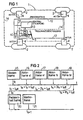
- a motor vehicle which is shown only schematically in Figure 1, is provided with a brake system 1, which includes (not shown) on each of its four wheels 2 brake, which is actuated by a respective electrically controlled brake actuator 4.
- the brakes are actuated by the driver of the motor vehicle by issuing a brake torque request via a brake pedal 5 which is connected to a pedal unit 6.
- the pedal unit 6 acts as a pedal force simulator. it is provided with a spring 7 and with one or more force sensors and at least one displacement sensor, which detect the operation of the brake pedal 5 by the driver and convert it into electrical signals.
- These sensors are summarized by a block 8 shown. The sensors not shown here are described in the above-mentioned earlier application.
- the pedal unit 6 is connected by a data bus 12 to a central controller 10 and to the brake actuators (or actuators) 4.
- An additional signal line 14 which allows a redundant transmission of control signals and data, also connects the pedal unit 6 to the central controller 10 and the brake actuators 4. In addition, it connects these actuators with each other.
- the type of data and signal transmission over the data bus 12 and the additional or redundant signal line 14 will be described below.
- the brake actuators 4 are mounted at a fully electric brake system directly to each wheel 2, since the application force for the respective brake is advantageously not transmitted over long stretches in the vehicle, while the detection of the driver braking torque request and the system control centrally at or in the Near the brake pedal 5 are located. It follows that the brake system is distributed over the entire vehicle.
- the brake actuator can generate the application force to the brake caliper in various ways, for Example of a mechanical or a hydraulic transmission.
- the electrical transmission of the braking torque requirement in the system to make special security requirements. It must be immune to interference and fault tolerant, ie occurring errors in the data and signal transmission (or: communication) must be reliably detected and there must be appropriate strategies for error handling. In addition, all participants in the communication must be able to detect a faulty behavior of other participants and even if communication fails, a minimum braking capability must be ensured.
- the driver's braking torque request is information transmitted as an electrical signal. This information must be repeated in a fixed time frame of a participant in the communication, the pedal unit 6 are detected and to several other participants in the communication, the brake actuators 4, are transmitted.
- the data of the electronic central control 10 - which performs additional braking functions, such as ABS, traction control, vehicle dynamics control and other functions - must be transmitted to the participants. For security reasons, additional data is exchanged between the participants.
- a data bus In motor vehicles, the CAN bus is often used. This is a standard 2-wire bus capable of transferring data between a large number of subscribers at rates between 100 kbit and 1000 kbit.
- This bus is event driven, i. Each date represents an event (event) which is transmitted digitally over electrical lines in the form of a specific data block (also: frames).
- the type of communication between the participants is prescribed and has to comply with certain forms, as well as the behavior in case of errors. For the data transmission in a brake system, however, some disadvantages would have to be taken into account, since this bus was not designed specifically for this task, but represents a general solution.
- the problem to be solved here requires a very regular communication in a fixed time grid, and therefore the event-driven structure is unfavorable. Also, the so-called communication overhead (many users possible) would drive up the required amount of data. In addition, the failure of a participant would be difficult to see because his communication would be tied to an event. In the event of an error, an avalanche-like increase in the data is possible, which can hinder the communication significantly and lead to a time-delayed processing of braking torque requirements. Especially this is a significant drawback, since such a case is difficult to avoid as part of the communication description. but a drastic restriction of security requirements means. These limitations are avoided by the solution described below.
- the driver's braking torque request is determined by means of sensors.
- the electronic central control or central control unit 10 which implements the higher electronic brake functions such as ABS, traction control, vehicle dynamics control, brake assist etc., forms an interface to other vehicle controls, for example the engine control. It can be arranged at any point in the motor vehicle. Their functions can be distributed to several control units, or even omitted for a very simple braking system.
- the basic function of the brake system 1 is as follows:
- the pedal unit 6 determines the driver's braking request, from this calculates a microprocessor 9 contained in it a clamping force of the brake caliper, which must be applied by the electric actuators (this can be done by a direct force generation or by pressure generation ).
- a corresponding application setpoint must be transmitted to the brake actuators 4.
- the brake actuator adjusts the clamping force independently and determines a clamping actual value.
- the central controller 10 may, according to the extent of the control functions contained therein, change the setpoints. For example, in an ABS case, it reduces the setpoints so that the respective wheel no longer blocked. In a vehicle dynamics system, the central control automatically requests application setpoint values on specific wheels.
- the data traffic takes place via the data bus 12, which is designed as a two-wire bus with symmetrical transmission of binary signals (for example according to RS 485 standard). All participants (brake actuators 4, pedal unit 6, central controller 10) each form a node of the data bus. For security reasons, no further nodes with send authorization are recorded on the bus (if the number of participants is as low as possible, the result is a low error rate).
- the data traffic is not event-controlled but time-controlled, i. Each participant receives a fixed time slot (or time slot) within a fixed cyclical sequence in which he has the authorization to send. For example, if each participant is assigned an equal time slot of 2 ms, the complete bus communication cycle takes 12 ms in a system with six subscribers, after which a new bus cycle begins (FIG. 2).
- a bus master begins with its data block 15 ( Figure 2) or "frame" the bus cycle, i. it transmits number 1 in the time slice.
- the central controller 10 acts as the bus master. All other participants respond to the transmission of the master data block.
- This connection is preferably in the form of a pulse width modulated data transmission, which realizes only the basic braking function, i. the measured driver's request (braking torque request) transmitted from the Pedaleinhei 6 to all participants.
- the data blocks used have a uniform data structure, they generally consist of twelve bytes: the first byte contains the identifier and the sender address, the second byte one instruction, bytes 3 to 11 data, byte 12 the checksum.
- the bus master begins to communicate with its first data block 15 after a self-initialization. This contains a time synchronization instruction. All participants synchronize to the time of the first bit of the block. Participants who are ready to send at this time send their data block within their time slice. These are data blocks 16, 17, 18 and 19 of the brake actuators 4 for the front wheel left vl, front wheel right vr, rear wheel left hl and rear wheel right hr, and a data block 20 of the pedal unit 6. Thereafter, the bus cycle starts again with the next master data block 21, etc.
- the bus master repeats the time synchronization every 50 ms, other subscribers can log on to it in their time slot. A participant who does not report at the beginning or later often fails blocks is turned off as disturbed.
- the transmission of a block takes approx. 1 ms, the time slice lasts 2 ms, within the time slice the time may vary, without this being considered an error. A transmission outside the time slice is not permitted and is treated as a serious error.
- the bus master sends the Zuspannkraftsoll values to the individual brake actuators 4, these regulate the clamping force generated by them to this target value, while a control loop of the brake actuator preferably has the same time duration as the data bus cycle.
- the brake actuator sends back a clamping force value (or an equivalent measurement result) measured by it to the bus master, together with other sensor data (e.g., wheel speed) determined at the brake actuator.
- driver request all the additional functions of the brake are realized, i. the brake torque request coming from the driver is changed in accordance with the results of the electronic brake management, for example reduced in the ABS case, or set up during a traction control on the drive axle.
- a new Zuspannsollkraft is calculated and shipped. Each participant observes the traffic on the bus and reacts to errors in the manner described below.
- the driver's request is measured and calculated by means of a safety circuit 10, which brings about, for example, a 2 out of 3 majority decision, from the sensor signals a braking torque request parallel to the central controller 10. It is constantly transmitted via PWM transmission to all other participants. As long as there is no change in the setpoint values by the central control (for example in the ABS case), the setpoint values must match for both transmissions, so that a check can be made of both data connections.
Landscapes
- Engineering & Computer Science (AREA)
- Transportation (AREA)
- Mechanical Engineering (AREA)
- Microelectronics & Electronic Packaging (AREA)
- Physics & Mathematics (AREA)
- Fluid Mechanics (AREA)
- Health & Medical Sciences (AREA)
- Computing Systems (AREA)
- General Health & Medical Sciences (AREA)
- Medical Informatics (AREA)
- Computer Networks & Wireless Communication (AREA)
- Signal Processing (AREA)
- Regulating Braking Force (AREA)
Claims (11)
- Système de freinage (1) pour un véhicule automobile comportant :- une unité de pédale (6), par laquelle des manoeuvres de la pédale de frein (5) du véhicule automobile sont reconnues par au moins un détecteur (8) et .par laquelle sont produites des valeurs de consigne de la force d'application du frein correspondant au souhait du conducteur,- des actionneurs de freinage (4) affectés aux roues (2) du véhicule automobile et actionnés électriquement,- une commande électronique centralisée (13), qui analyse les signaux des détecteurs et par laquelle sont produits des signaux de commande de fonctions supplémentaires de freinage,- un bus de donnés (12), reliant les uns aux autres l'unité de pédale (6), les actionneurs de freinage (4) et la commande centralisée (13) et par l'intermédiaire duquel des blocs de données sont échangés dans une trame de temps prescrite qui se répète cycliquement, et- une ligne supplémentaire de signalisation (14), reliant les uns aux autres l'unité de pédale (6), les actionneurs de freinage (4) et la commande centralisée (13) et par l'intermédiaire de laquelle la valeur de consigne de la force d'application du frein est transmise de l'unité de pédale (6) aux actionneurs de freinage (4) et à la commande centralisée (13) et des données concernant l'état des dispositifs raccordés sont échangées, les données étant transmises par la ligne supplémentaire de signalisation (14) sous la forme de signaux à modulation d'impulsion en largeur.
- Système de freinage selon la revendication 1, caractérisée par le fait que le bus de données (12) est conçu en tant que bus à deux fils pour une transmission symétrique de signaux numériques et que les participants, qui lui sont raccordés, à savoir les actionneurs de freinage (4), l'unité de pédale (6) et la commande centralisée (13), forment des noeuds à chacun desquels est affecté, dans un cycle de transmission, par un participant défini comme maître du bus, une fenêtre de temps fixe ayant une autorisation exclusive d'émission.
- Système de freinage selon l'une des revendications précédentes, caractérisé par le fait que l'unité de pédale (6) comporte un circuit de sécurité (10) par lequel le souhait du conducteur est déterminé en tant que décision majoritaire à partir des signaux de plusieurs détecteurs (8) redondants qui relèvent le mouvement de la pédale.
- Système de freinage selon l'une des revendications précédentes, caractérisé par le fait que les actionneurs de freinage (4) sont conçus en tant que régulateurs qui règlent la force d'application des freins sur la valeur de consigne reçues.
- Procédé de transmission de données dans un système de freinage de véhicule automobile commandé électriquement, au cours duquel on exécute les stades suivants :- les données sont échangées cycliquement par l'intermédiaire d'un bus de données (12) entre plusieurs actionneurs de freinage (4), raccordés en tant que participants au bus de données (12), une unité de pédale (6) ou une commande centralisée électronique (13) ;- un participant, qui agit comme maître du bus, synchronise tous les participants sur une trame de temps universelle et détermine, pour chaque participant, une fenêtre de temps fixe dans un cycle de communication, dans laquelle il a autorisation exclusive d'émission ;- les divers participants émettent des blocs de données (16-20), qui renferment des indications concernant le cycle de transmission en cours et l'expéditeur, les données correspondantes et une somme de contrôle, et- les données émises par les participants renferment les demandes de couple de freinage du conducteur et de la commande électronique, des valeurs de mesure fournies par les détecteurs (8) et des paramètres d'état des participants.
- Procédé selon la revendication 5, caractérisé par le fait que, par un bloc de données non transmis dans une fenêtre de temps, le participant, qui est affecté à la fenêtre de temps, est reconnu comme défaillant.
- Procédé selon la revendication 5, caractérisé par le fait que, grâce à un scénario d'erreur qui se présente dans une fenêtre de temps, on reconnaît qu'un participant émet dans une mauvaise fenêtre de temps.
- Procédé selon l'une des revendications 5 à 7, caractérisé par le fait que, par l'intermédiaire d'une ligne de signalisation supplémentaire (14), qui relie les uns aux autres l'unité de pédale (6), les actionneurs de freinage (4) et la commande centralisée (13), on transmet une valeur de consigne de la force d'application du frein de l'unité de pédale (6) aux actionneurs de freinage (4) et à la commande centralisée (13) et on échange des données concernant l'état des dispositifs raccordés.
- Procédé selon la revendication 8, caractérisé par le fait que les données sont transmises sous forme de signaux à modulation d'impulsions en largeur sur la ligne de signalisation supplémentaire (14).
- Procédé selon la revendication 8, caractérisé par le fait que, si la fonction supplémentaire de freinage n'est pas active, des erreurs sont reconnues par comparaison des valeurs de consigne de la force d'application du frein transmises sur le bus de données (12) avec les valeurs de consignes de la force d'application du frein transmises sur la ligne de signalisation supplémentaire (14).
- Procédé selon la revendication 8, caractérisé par le fait que la ligne de signalisation supplémentaire (14) est conçue comme guide d'ondes optiques et que les signaux sont transmis optiquement.
Applications Claiming Priority (3)
| Application Number | Priority Date | Filing Date | Title |
|---|---|---|---|
| DE19706479 | 1997-02-19 | ||
| DE19706479 | 1997-02-19 | ||
| PCT/DE1998/000289 WO1998036956A1 (fr) | 1997-02-19 | 1998-02-02 | Systeme de freinage pour automobile et procede de transmission de donnees dans un systeme de freinage d'automobile, a commande electrique |
Publications (3)
| Publication Number | Publication Date |
|---|---|
| EP0961724A1 EP0961724A1 (fr) | 1999-12-08 |
| EP0961724B1 EP0961724B1 (fr) | 2002-05-02 |
| EP0961724B2 true EP0961724B2 (fr) | 2007-09-12 |
Family
ID=7820784
Family Applications (1)
| Application Number | Title | Priority Date | Filing Date |
|---|---|---|---|
| EP98909315A Expired - Lifetime EP0961724B2 (fr) | 1997-02-19 | 1998-02-02 | Systeme de freinage pour automobile et procede de transmission de donnees dans un systeme de freinage d'automobile a commande electrique |
Country Status (4)
| Country | Link |
|---|---|
| EP (1) | EP0961724B2 (fr) |
| JP (1) | JP3288390B2 (fr) |
| DE (1) | DE59803979D1 (fr) |
| WO (1) | WO1998036956A1 (fr) |
Cited By (2)
| Publication number | Priority date | Publication date | Assignee | Title |
|---|---|---|---|---|
| DE102011116642A1 (de) * | 2011-10-20 | 2013-04-25 | Audi Ag | Übertragungseinrichtung und Verfahren zur sicheren Übertragung eines Sensorsignals an ein Übertragungsziel und Kraftfahrzeug |
| DE102024108677A1 (de) * | 2024-03-27 | 2025-10-02 | Continental Automotive Technologies GmbH | Redundantes Bremssystem für ein Fahrzeug und Verfahren zur Steuerung eines Bremssystems |
Families Citing this family (22)
| Publication number | Priority date | Publication date | Assignee | Title |
|---|---|---|---|---|
| DE19949258C2 (de) * | 1999-10-13 | 2001-08-02 | Bayerische Motoren Werke Ag | Bremsanlage für Kraftfahrzeuge |
| US6317675B1 (en) | 1997-11-22 | 2001-11-13 | Continental Teves Ag & Co., Ohg | Electromechanical brake system |
| DE19755431A1 (de) * | 1997-12-13 | 1999-06-17 | Wabco Gmbh | Fahrzeugbremsanlage |
| DE19756976C2 (de) * | 1997-12-20 | 2000-05-11 | Daimler Chrysler Ag | Bremseinrichtung für Fahrzeuge |
| DE19836690A1 (de) * | 1998-08-13 | 2000-02-17 | Continental Teves Ag & Co Ohg | Pedaleinheit für eine elektromechanische Bremsanlage |
| DE29823179U1 (de) * | 1998-12-29 | 2000-05-11 | Schunk Motorensysteme GmbH, 27777 Ganderkesee | Anordnung in einem Regelkreis zur Ansteuerung eines Motors eines Hilfsantriebs in einem Fahrzeug |
| US7281770B1 (en) * | 2000-08-08 | 2007-10-16 | Ford Global Technologies, Llc | System and method for regenerative and antiskid braking within an electric vehicle |
| DE10329016B3 (de) * | 2003-06-27 | 2004-10-21 | Daimlerchrysler Ag | Steuerungssystem für ein Kraftfahrzeug |
| JP4379793B2 (ja) | 2004-03-12 | 2009-12-09 | 株式会社デンソー | 車両用電子制御装置 |
| FR2877302B1 (fr) * | 2004-10-29 | 2008-05-09 | Renault Sas | Systeme de freinage a commande electrique |
| DE102004060459A1 (de) * | 2004-12-16 | 2006-07-06 | Bayerische Motoren Werke Ag | Datenbussystem für Kraftfahrzeuge und Verfahren zur Diagnose |
| US7676342B2 (en) | 2004-12-23 | 2010-03-09 | Asml Netherlands B.V. | Sensor assembly, digital serial bus and protocol, sensor network, and lithographic apparatus and system |
| DE102006059919A1 (de) * | 2006-12-19 | 2008-07-03 | Robert Bosch Gmbh | Datenverarbeitungssystem für ein Kraftfahreug |
| DE102007001371A1 (de) * | 2007-01-09 | 2008-07-10 | Siemens Ag | Redundante Übermittlung von Bremsanweisungen |
| DE102007021646A1 (de) * | 2007-05-09 | 2008-11-13 | Wabco Gmbh | Modulator |
| DE102007052710B4 (de) * | 2007-11-06 | 2011-02-17 | Wabco Gmbh | Elektropneumatische Bremssteuerungsanordnung für ein Fahrzeug |
| US20090189441A1 (en) * | 2008-01-29 | 2009-07-30 | Paul Degoul | Distributed electrical/electronic architectures for brake-by-wire brake systems |
| DE102010031608A1 (de) | 2009-07-31 | 2011-02-03 | Continental Teves Ag & Co. Ohg | Elektronisches Bremssystem und Verfahren zum Betrieb eines elektronischen Bremssystems |
| FR2974339B1 (fr) * | 2011-04-19 | 2014-08-29 | Renault Sa | Procede et systeme de commande de l'allumage de feux de stop d'un vehicule automobile, et vehicule equipe d'un tel systeme |
| JP6266281B2 (ja) * | 2013-09-18 | 2018-01-24 | 日立オートモティブシステムズ株式会社 | 自動車用電子制御装置 |
| DE102019104955A1 (de) | 2019-02-27 | 2020-08-27 | Wabco Gmbh | Übertragung eines wertes mittels eines pulsweiten-modulierten signals |
| DE102024204790A1 (de) | 2024-05-24 | 2025-11-27 | Robert Bosch Gesellschaft mit beschränkter Haftung | Verfahren zum Betrieb eines Fremdkraftbremssystems, Fremdkraftbremssystem und Kraftfahrzeug |
Citations (3)
| Publication number | Priority date | Publication date | Assignee | Title |
|---|---|---|---|---|
| EP0247026A2 (fr) † | 1986-05-16 | 1987-11-25 | Austria Mikrosysteme International Gmbh | Procédé de synchronisation des horloges des dispositifs de calcul reliés à un système de communication et dispositifs de calcul à cet effet |
| US4995483A (en) † | 1989-12-18 | 1991-02-26 | Aircraft Braking Systems Corporation | Motor position feedback controlled electrically actuated aircraft brake |
| WO1994006080A1 (fr) † | 1992-09-04 | 1994-03-17 | Fault Tolerant Systems | Controleur de communication et procede de transmission d'informations |
Family Cites Families (3)
| Publication number | Priority date | Publication date | Assignee | Title |
|---|---|---|---|---|
| DE19509133C2 (de) * | 1994-04-11 | 2003-07-17 | Daimler Chrysler Ag | Anordnung zur Überwachung von Zweidraht-Busleitungen |
| GB9516414D0 (en) * | 1995-08-10 | 1995-10-11 | Genrad Ltd | Electronic diagnostic system |
| DE19529434B4 (de) * | 1995-08-10 | 2009-09-17 | Continental Teves Ag & Co. Ohg | Microprozessorsystem für sicherheitskritische Regelungen |
-
1998
- 1998-02-02 EP EP98909315A patent/EP0961724B2/fr not_active Expired - Lifetime
- 1998-02-02 JP JP53613898A patent/JP3288390B2/ja not_active Expired - Fee Related
- 1998-02-02 DE DE59803979T patent/DE59803979D1/de not_active Expired - Fee Related
- 1998-02-02 WO PCT/DE1998/000289 patent/WO1998036956A1/fr not_active Ceased
Patent Citations (3)
| Publication number | Priority date | Publication date | Assignee | Title |
|---|---|---|---|---|
| EP0247026A2 (fr) † | 1986-05-16 | 1987-11-25 | Austria Mikrosysteme International Gmbh | Procédé de synchronisation des horloges des dispositifs de calcul reliés à un système de communication et dispositifs de calcul à cet effet |
| US4995483A (en) † | 1989-12-18 | 1991-02-26 | Aircraft Braking Systems Corporation | Motor position feedback controlled electrically actuated aircraft brake |
| WO1994006080A1 (fr) † | 1992-09-04 | 1994-03-17 | Fault Tolerant Systems | Controleur de communication et procede de transmission d'informations |
Non-Patent Citations (3)
| Title |
|---|
| ATZ 98(1996), Balz et al. : "Konzept für eine elktromechanische Pahrzeugbremse" † |
| Hinsch, Hermann :"Elektronik : ein Werkzeug für Naturwissenschaftler,Pulsmodulation (PM), Seite 220"(Springer-Verlag 1996) † |
| Manfred Burckhardt : "Radschlupf-Regelsysteme", Fahrwerktechnik, 1. Auflage, Vogel-Verlag,1993 † |
Cited By (3)
| Publication number | Priority date | Publication date | Assignee | Title |
|---|---|---|---|---|
| DE102011116642A1 (de) * | 2011-10-20 | 2013-04-25 | Audi Ag | Übertragungseinrichtung und Verfahren zur sicheren Übertragung eines Sensorsignals an ein Übertragungsziel und Kraftfahrzeug |
| DE102024108677A1 (de) * | 2024-03-27 | 2025-10-02 | Continental Automotive Technologies GmbH | Redundantes Bremssystem für ein Fahrzeug und Verfahren zur Steuerung eines Bremssystems |
| WO2025201893A1 (fr) | 2024-03-27 | 2025-10-02 | Continental Automotive Technologies GmbH | Système de freinage redondant pour véhicule et procédé de commande d'un système de freinage |
Also Published As
| Publication number | Publication date |
|---|---|
| JP2000510077A (ja) | 2000-08-08 |
| EP0961724A1 (fr) | 1999-12-08 |
| WO1998036956A1 (fr) | 1998-08-27 |
| JP3288390B2 (ja) | 2002-06-04 |
| EP0961724B1 (fr) | 2002-05-02 |
| DE59803979D1 (de) | 2002-06-06 |
Similar Documents
| Publication | Publication Date | Title |
|---|---|---|
| EP0961724B1 (fr) | Systeme de freinage pour automobile et procede de transmission de donnees dans un systeme de freinage d'automobile a commande electrique | |
| EP4048565B1 (fr) | Système de freinage pour un véhicule à moteur | |
| EP2176106B1 (fr) | Système de freinage pour véhicule et procédé d'exploitation d'un système de freinage pour véhicule | |
| EP0780276B1 (fr) | Dispositif de freinage pour un véhicule | |
| EP2183136B1 (fr) | Système de freinage pour véhicule et procédé d'exploitation d'un système de freinage pour véhicule | |
| DE4227084B4 (de) | Druckregelmodul einer Druckluft-Fahrzeugbremsanlage | |
| EP0832800B1 (fr) | Système de freinage électronique pour véhicules à roues | |
| EP4114696B1 (fr) | Systeme de freinage avec controle redondante du frein de stationnement | |
| DE102009001081B3 (de) | Vorrichtung und Verfahren zum Übertragen von Daten und Energie über Einrichtungen eines Netzwerkes | |
| DE19756976C2 (de) | Bremseinrichtung für Fahrzeuge | |
| DE4110372A1 (de) | Multiplex-uebertragungssystem fuer fahrzeuge | |
| DE102008024180A1 (de) | Kombinierte Bremsanlage, insbesondere für Kraftfahrzeuge | |
| DE69129510T2 (de) | Multiplex-Übertragungssystem für Kraftfahrzeuge | |
| EP3385934A1 (fr) | Dispositif de commande d'un processus relatif à la sécurité, procédé d'essai de la capacité de fonctionnement dudit dispositif ainsi que véhicule doté dudit dispositif | |
| EP2459426A1 (fr) | Système de freinage électronique et procédé permettant de faire fonctionner un système de freinage électronique | |
| DE19937159A1 (de) | Elektrisch gesteuertes Bremssystem | |
| DE10104194B4 (de) | X-By-Wire-System für ein Kraftfahrzeug | |
| DE102022205986A1 (de) | Verfahren zur Steuerung eines hydraulischen Bremssystems und Bremssystem | |
| DE4210094C2 (de) | Multiplexes Übertragungsverfahren | |
| DE102018200313A1 (de) | Verfahren zum Herstellen eines Steuersystems für ein Kraftfahrzeug, Steuersystem | |
| WO2023174494A1 (fr) | Procédé de commande d'un système de freinage hydraulique et système de freinage | |
| EP1163778B1 (fr) | Circuit et procede pour configurer une interface de dispositif de commande ou de regulation | |
| DE10324724A1 (de) | Redundanter CAN-Datenbus | |
| DE2849008C2 (de) | Verfahren zur Abbremsung von kontinuierlich beeinflußten Schienenfahrzeugen bei Übertragungsausfall | |
| DE102024108677A1 (de) | Redundantes Bremssystem für ein Fahrzeug und Verfahren zur Steuerung eines Bremssystems |
Legal Events
| Date | Code | Title | Description |
|---|---|---|---|
| PUAI | Public reference made under article 153(3) epc to a published international application that has entered the european phase |
Free format text: ORIGINAL CODE: 0009012 |
|
| 17P | Request for examination filed |
Effective date: 19990805 |
|
| AK | Designated contracting states |
Kind code of ref document: A1 Designated state(s): DE FR GB IT |
|
| GRAG | Despatch of communication of intention to grant |
Free format text: ORIGINAL CODE: EPIDOS AGRA |
|
| GRAG | Despatch of communication of intention to grant |
Free format text: ORIGINAL CODE: EPIDOS AGRA |
|
| GRAH | Despatch of communication of intention to grant a patent |
Free format text: ORIGINAL CODE: EPIDOS IGRA |
|
| 17Q | First examination report despatched |
Effective date: 20010903 |
|
| REG | Reference to a national code |
Ref country code: GB Ref legal event code: IF02 |
|
| GRAH | Despatch of communication of intention to grant a patent |
Free format text: ORIGINAL CODE: EPIDOS IGRA |
|
| GRAA | (expected) grant |
Free format text: ORIGINAL CODE: 0009210 |
|
| AK | Designated contracting states |
Kind code of ref document: B1 Designated state(s): DE FR GB IT |
|
| REG | Reference to a national code |
Ref country code: GB Ref legal event code: FG4D Free format text: NOT ENGLISH |
|
| REF | Corresponds to: |
Ref document number: 59803979 Country of ref document: DE Date of ref document: 20020606 |
|
| GBT | Gb: translation of ep patent filed (gb section 77(6)(a)/1977) |
Effective date: 20020720 |
|
| ET | Fr: translation filed | ||
| PLBI | Opposition filed |
Free format text: ORIGINAL CODE: 0009260 |
|
| PLBQ | Unpublished change to opponent data |
Free format text: ORIGINAL CODE: EPIDOS OPPO |
|
| PLBF | Reply of patent proprietor to notice(s) of opposition |
Free format text: ORIGINAL CODE: EPIDOS OBSO |
|
| 26 | Opposition filed |
Opponent name: DAIMLERCHRYSLER AG Effective date: 20030203 |
|
| PLAX | Notice of opposition and request to file observation + time limit sent |
Free format text: ORIGINAL CODE: EPIDOSNOBS2 |
|
| PLBB | Reply of patent proprietor to notice(s) of opposition received |
Free format text: ORIGINAL CODE: EPIDOSNOBS3 |
|
| RAP2 | Party data changed (patent owner data changed or rights of a patent transferred) |
Owner name: PACIFICA GROUP TECHNOLOGIES PTY LTD |
|
| PUAH | Patent maintained in amended form |
Free format text: ORIGINAL CODE: 0009272 |
|
| STAA | Information on the status of an ep patent application or granted ep patent |
Free format text: STATUS: PATENT MAINTAINED AS AMENDED |
|
| 27A | Patent maintained in amended form |
Effective date: 20070912 |
|
| AK | Designated contracting states |
Kind code of ref document: B2 Designated state(s): DE FR GB IT |
|
| GBTA | Gb: translation of amended ep patent filed (gb section 77(6)(b)/1977) | ||
| ET3 | Fr: translation filed ** decision concerning opposition | ||
| REG | Reference to a national code |
Ref country code: GB Ref legal event code: 732E |
|
| REG | Reference to a national code |
Ref country code: FR Ref legal event code: TP |
|
| PGFP | Annual fee paid to national office [announced via postgrant information from national office to epo] |
Ref country code: DE Payment date: 20090129 Year of fee payment: 12 |
|
| PGFP | Annual fee paid to national office [announced via postgrant information from national office to epo] |
Ref country code: GB Payment date: 20090119 Year of fee payment: 12 |
|
| PGFP | Annual fee paid to national office [announced via postgrant information from national office to epo] |
Ref country code: IT Payment date: 20090226 Year of fee payment: 12 |
|
| PGFP | Annual fee paid to national office [announced via postgrant information from national office to epo] |
Ref country code: FR Payment date: 20090107 Year of fee payment: 12 |
|
| GBPC | Gb: european patent ceased through non-payment of renewal fee |
Effective date: 20100202 |
|
| REG | Reference to a national code |
Ref country code: FR Ref legal event code: ST Effective date: 20101029 |
|
| PG25 | Lapsed in a contracting state [announced via postgrant information from national office to epo] |
Ref country code: FR Free format text: LAPSE BECAUSE OF NON-PAYMENT OF DUE FEES Effective date: 20100301 |
|
| PG25 | Lapsed in a contracting state [announced via postgrant information from national office to epo] |
Ref country code: DE Free format text: LAPSE BECAUSE OF NON-PAYMENT OF DUE FEES Effective date: 20100901 |
|
| PG25 | Lapsed in a contracting state [announced via postgrant information from national office to epo] |
Ref country code: GB Free format text: LAPSE BECAUSE OF NON-PAYMENT OF DUE FEES Effective date: 20100202 Ref country code: IT Free format text: LAPSE BECAUSE OF NON-PAYMENT OF DUE FEES Effective date: 20100202 |