EP0961886B1 - Dispositif elastique d'orientation radiale pour un volant amortisseur double de transmission de vehicule automobile - Google Patents
Dispositif elastique d'orientation radiale pour un volant amortisseur double de transmission de vehicule automobile Download PDFInfo
- Publication number
- EP0961886B1 EP0961886B1 EP98963584A EP98963584A EP0961886B1 EP 0961886 B1 EP0961886 B1 EP 0961886B1 EP 98963584 A EP98963584 A EP 98963584A EP 98963584 A EP98963584 A EP 98963584A EP 0961886 B1 EP0961886 B1 EP 0961886B1
- Authority
- EP
- European Patent Office
- Prior art keywords
- spring
- elastic
- elastic device
- washer
- springs
- Prior art date
- Legal status (The legal status is an assumption and is not a legal conclusion. Google has not performed a legal analysis and makes no representation as to the accuracy of the status listed.)
- Expired - Lifetime
Links
- 230000005540 biological transmission Effects 0.000 title 1
- 230000006835 compression Effects 0.000 claims description 13
- 238000007906 compression Methods 0.000 claims description 13
- 238000013016 damping Methods 0.000 claims description 12
- 208000031968 Cadaver Diseases 0.000 description 4
- 239000000463 material Substances 0.000 description 4
- 239000002184 metal Substances 0.000 description 4
- 229910052751 metal Inorganic materials 0.000 description 4
- 230000003071 parasitic effect Effects 0.000 description 4
- 230000008901 benefit Effects 0.000 description 3
- 238000006243 chemical reaction Methods 0.000 description 3
- 238000002485 combustion reaction Methods 0.000 description 3
- 239000007858 starting material Substances 0.000 description 2
- 238000003466 welding Methods 0.000 description 2
- 229910001018 Cast iron Inorganic materials 0.000 description 1
- 210000004027 cell Anatomy 0.000 description 1
- 150000001875 compounds Chemical class 0.000 description 1
- 230000008878 coupling Effects 0.000 description 1
- 238000010168 coupling process Methods 0.000 description 1
- 238000005859 coupling reaction Methods 0.000 description 1
- 238000002788 crimping Methods 0.000 description 1
- 230000001627 detrimental effect Effects 0.000 description 1
- 238000006073 displacement reaction Methods 0.000 description 1
- 229920001971 elastomer Polymers 0.000 description 1
- 239000000806 elastomer Substances 0.000 description 1
- 239000002783 friction material Substances 0.000 description 1
- 238000004519 manufacturing process Methods 0.000 description 1
- 238000000034 method Methods 0.000 description 1
- 244000045947 parasite Species 0.000 description 1
- 230000002093 peripheral effect Effects 0.000 description 1
- 230000000284 resting effect Effects 0.000 description 1
- 235000013580 sausages Nutrition 0.000 description 1
Images


Classifications
-
- F—MECHANICAL ENGINEERING; LIGHTING; HEATING; WEAPONS; BLASTING
- F16—ENGINEERING ELEMENTS AND UNITS; GENERAL MEASURES FOR PRODUCING AND MAINTAINING EFFECTIVE FUNCTIONING OF MACHINES OR INSTALLATIONS; THERMAL INSULATION IN GENERAL
- F16F—SPRINGS; SHOCK-ABSORBERS; MEANS FOR DAMPING VIBRATION
- F16F15/00—Suppression of vibrations in systems; Means or arrangements for avoiding or reducing out-of-balance forces, e.g. due to motion
- F16F15/10—Suppression of vibrations in rotating systems by making use of members moving with the system
- F16F15/12—Suppression of vibrations in rotating systems by making use of members moving with the system using elastic members or friction-damping members, e.g. between a rotating shaft and a gyratory mass mounted thereon
- F16F15/131—Suppression of vibrations in rotating systems by making use of members moving with the system using elastic members or friction-damping members, e.g. between a rotating shaft and a gyratory mass mounted thereon the rotating system comprising two or more gyratory masses
- F16F15/133—Suppression of vibrations in rotating systems by making use of members moving with the system using elastic members or friction-damping members, e.g. between a rotating shaft and a gyratory mass mounted thereon the rotating system comprising two or more gyratory masses using springs as elastic members, e.g. metallic springs
- F16F15/134—Wound springs
- F16F15/13407—Radially mounted springs
-
- F—MECHANICAL ENGINEERING; LIGHTING; HEATING; WEAPONS; BLASTING
- F16—ENGINEERING ELEMENTS AND UNITS; GENERAL MEASURES FOR PRODUCING AND MAINTAINING EFFECTIVE FUNCTIONING OF MACHINES OR INSTALLATIONS; THERMAL INSULATION IN GENERAL
- F16F—SPRINGS; SHOCK-ABSORBERS; MEANS FOR DAMPING VIBRATION
- F16F1/00—Springs
- F16F1/02—Springs made of steel or other material having low internal friction; Wound, torsion, leaf, cup, ring or the like springs, the material of the spring not being relevant
- F16F1/04—Wound springs
- F16F1/12—Attachments or mountings
- F16F1/128—Attachments or mountings with motion-limiting means, e.g. with a full-length guide element or ball joint connections; with protective outer cover
-
- F—MECHANICAL ENGINEERING; LIGHTING; HEATING; WEAPONS; BLASTING
- F16—ENGINEERING ELEMENTS AND UNITS; GENERAL MEASURES FOR PRODUCING AND MAINTAINING EFFECTIVE FUNCTIONING OF MACHINES OR INSTALLATIONS; THERMAL INSULATION IN GENERAL
- F16F—SPRINGS; SHOCK-ABSORBERS; MEANS FOR DAMPING VIBRATION
- F16F3/00—Spring units consisting of several springs, e.g. for obtaining a desired spring characteristic
- F16F3/02—Spring units consisting of several springs, e.g. for obtaining a desired spring characteristic with springs made of steel or of other material having low internal friction
- F16F3/04—Spring units consisting of several springs, e.g. for obtaining a desired spring characteristic with springs made of steel or of other material having low internal friction composed only of wound springs
Definitions
- the present invention relates to an elastic device for a double damping flywheel intended to be installed radially for elastic coupling the two rotating masses of the double flywheel.
- the invention relates more particularly to an elastic device for a double shock-absorbing flywheel for a motor vehicle comprising a first mass rotating suitable for being linked in rotation to a driving shaft, a second mass rotating revolving mounted on the first mass using a bearing and adapted to form the reaction plate of a friction clutch capable of being linked in rotation by disengageable to a driven shaft, and a series of elastic devices implanted in a radial general direction to elastically couple the second mass rotating at the first rotating mass, each of the elastic devices being articulated, on the one hand on the first rotating mass via a first axis parallel to the axis of rotation of the double flywheel, and secondly on the second rotating mass via a second axis, parallel to the first axis.
- the elastic means are constituted by a helical spring, sausage, compression whose two opposite axial ends are in support mutual against the two support washers.
- each device uses a large dimensioned spring which consequence, taking into account the need to reduce the overall size of these devices, is adjacent to the internal face of the second tubular element against which it is therefore in frictional contact, this arrangement also being necessary to ensure good support and good guidance of the spring, thus avoiding noise generating parasitic movements.
- the object of the present invention is to propose a new design for telescopic elements of an elastic device of the type described and shown in document WO-A-94 / 27.062 which remedies these drawbacks.
- the invention provides an elastic device characterized in that that the elastic means comprise at least two springs of different stiffness which are mounted axially in series between the first and second support washers, which are crossed by the central rod, and among which a first spring, of stiffness the strongest, intervenes without friction between its body and the internal surface of the body tubular of the second element.
- the second spring when the second spring comes into contiguous turns, we still benefits from an elasticity without the first spring rubbing against the body and therefore disturb the friction devices.
- the second spring is not active in the second phase and therefore not bothersome.
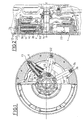
- FIGS. 1 and 2 show a double torsional damping flywheel comprising two coaxial parts 1 and 2 mounted movable in rotation relative to one another to the other, around a common axis X-X, against a series of devices cushioning bands 10.
- the first part 1 consists of a plate 11 and the second part also consists of a plate 21 extending parallel to the plate 11.
- the plates 11 and 21 are made of moldable material, usually cast iron, to increase their inertia. Parts 1 and 2 therefore constitute masses rotating.
- the second rotating mass 2 is rotatably mounted on a hub tubular 14 carried by the first rotating mass 11.
- the hub 14 is a part of generally coaxial cylindrical shape, with an axis X-X, with rotating masses 1 and 2 which is here made in one piece with the plate 11.
- the hub 14 can be attached to the plate 11, and a bearing 15, here a ball bearing, is interposed between the outer periphery of the hub 14 and the internal periphery of the plate 21.
- the second mass 2 which is rotatably mounted on the rotating mass 1 by means of the bearing 15, constitutes by its plate 21 the reaction plate a friction clutch 13 comprising a cover fixed on the plate 21, a diaphragm resting on the bottom of the cover to urge a pressure plate towards the reaction plate 21 to tighten the friction linings of a disc friction between said plates.
- the first rotating mass is intended to be connected, for example screws not shown, by its internal periphery to a drive shaft, here to the crankshaft (not shown) of the internal combustion engine of the motor vehicle, while the second rotating mass is disengageable in rotation by through the clutch 13 to the input shaft 17 of the gearbox of the vehicle.
- the first rotating mass 1 forming a plate is formed for essentially by a central part 11 of transverse orientation, in the form of a plate or flange, which carries at its outer periphery a starter ring 13 provided to be driven by the pinion of a starter (not shown) of the engine combustion of a motor vehicle fitted with a damping flywheel.
- the elastic damping means include a series of elastic devices 10 and they intervene globally in the direction radial between the plates 11 and 21, and therefore between the two rotating masses 1 and 2.
- each elastic device comprises a first articulation head 30 arranged radially inwards so as to allow the articulated mounting of the elastic device around a Y-Y axis parallel to the X-X axis.
- each first articulation head 30 is mounted, articulated on the second rotating mass 2 by via a hinge pin 32 riveted on the part located radially towards inside the plate 21 of the second rotating mass 2.
- Each elastic device 10 is also mounted articulated on the first rotating mass 1, radially outward, by means of a second head articulation 34 which is crossed by an articulation rod 36 carried by the first rotating mass 1 and of axis Z-Z parallel to the axes X-X and Y-Y.
- each elastic device 10 tends to bring its two articulation heads 30 and 34 radially towards each other, that is to say to constitute globally the equivalent of a tension spring which tends to lengthen (see figure 1) when the two rotating masses 1 and 2 rotate one relative to the other, the elastic devices 10 resiliently recalling the rotating masses 1 and 2 in their angular position of rest illustrated in FIGS. 1 and 2, in which each device 10 of generally radial orientation, that is to say that the straight line D passing through the axes Z-Z and Y-Y is generally of radial orientation.
- Each elastic device 10 shown in the figures, consists of two telescopic elements capable of sliding axially, one with respect to the other along line D which is the geometric sliding axis.
- the first telescopic element is constituted by the articulation head 30 produced in the form of a ring which extends radially from its surface cylindrical device 40 by a massive rod 42 oriented in the direction D of telescopic sliding.
- the ring 31 receives a rivet 32 with interposition of a bearing bush not referenced.
- the rod 42 is for example fixed by welding to the articulation ring 30, or made in one piece, and it extends axially inside means compression elastics that each elastic device 10 comprises.
- the free end 48 of the rod 42 passes through a first metal washer 50.
- the free end 48 is welded into a hole 52 in the first washer 50.
- the production of the washer 50 which constitutes the first support washer for the first axial end of the elastic means, is such that it brings to its outer periphery an annular sliding pad 35 made of low coefficient material friction which is fixed to it by an elastic axial retaining ring 37 received in a washer groove 50.
- the second axial end of the elastic means is in axial support against a second metal support washer 58.
- the washer 58 is slidably traversed by the body of the rod 42.
- the metal washer 58 carries at its internal periphery an annular pad of slip 39 made of a material with a low coefficient of friction attached to it by a elastic axial retaining ring 41 received in a groove in the washer 58.
- the second washer 58 belongs to the second telescopic element of the elastic device 10 which comprises the second articulation head 34 and a body external 60 of generally tubular shape with circular annular cylindrical section.
- the tubular body 60 a guide tube, which is a metal part treated, the dimensions of which are such that the first support washer 50 with its sliding shoe is received sliding inside 62 of body 60, while its free end edge 64 is fixed, for example by crimping or welding against the cylindrical peripheral edge 66 of the second support washer 58.
- the tubular body 60 is extends by a transverse bottom 70 opposite which extends the first washer 50.
- This bottom 70 is extended by a head 34 pierced in its center by a hole 74 intended to receive the articulation rod 36 with the interposition of a bearing sleeve 75.
- the elastic means axially interposed between the two washers 50 and 58 are constituted by at least two coil springs 100 and 102 of different stiffnesses which are mounted in series from the point of view of their elastic action in axial compression.
- the first spring 100 which is the strongest spring, is here a helical compression spring which is axially interposed between the first support washer 50, against which it is supported by its first end turn upper 104, considering the figures, and an intermediate washer 106 against which it supports indirectly via its second turn lower end 108; the washer 106 being traversed axially with radial clearance by the body of the rod 42 and being itself received with radial clearance inside the second tubular element 60.
- the cage 110 internally houses an annular cylindrical bearing 116 in low friction material that slides along the body of the rod 42 while slidingly guiding the lower end of the first spring 100 and so all of this first spring.
- This cage 110 is metallic and is produced by stamping and protecting the bearing 116.
- the first spring 100 of the highest stiffness present an overall outside diameter reduced compared to the diameter of the internal surface cylindrical 62 of the second tubular element 60 so as to permanently spare a radial clearance "J" between these two elements to avoid the appearance of any phenomenon of friction, and therefore friction forces arising therefrom, between the first spring 100 and the second tubular element 60.
- the second spring 102 is a helical compression spring mounted at the lower part of the device 10 which is a spring of larger diameter than the first spring 100 and which is itself produced in a wire of larger diameter.
- the second spring 102 is supported axially by its first turn upper end 118 against the underside of the intermediate washer 106 and it is supported axially by its second lower end turn 120 against the second support washer 58.
- the second spring 102 of lower stiffness has the maximum permissible dimensions so to be able to be received inside the second tubular element 60, that is to say that the external surface of its turns is partly in frictional contact with the surface internal 62 of the tubular element 60.
- the second spring 102 In order to further increase the stiffness of the second spring 102, it can be associated in parallel with another coil spring with coaxial and internal coil 122 according to a so-called "compound" arrangement.
- This device 23 comprises a control washer driven in rotation by the rod 36 as described in document FR 96 12098 filed on 30/03/1996. More specifically, the rod 42 drives the washer 50 which drives the intermediate washer 106 through the first stiffer spring 100, and it then acts directly on the springs 102 and 122 at the way of a conventional device 10 of the type illustrated in FIGS.
- the spring 100 never comes into contact with the surface 62 due to the play "J" and there is an elasticity when the springs 102, 122 have contiguous turns.
- the end of intervention of the first spring 100 corresponds to its state compressed, that is to say when all the turns are contiguous.
- the first spring 100 of the highest stiffness is constituted by a frustoconical elastic washer which is directly interposed between the first support washer 50 and the washer intermediate 46.
- the other elements or components of the elastic device 10 according to this second embodiment are identical to those described with reference to the first embodiment illustrated in Figures 3 and 4 and the operation of the device in two successive phases without parasitic friction then with possibly parasitic friction is identical to what has been described previously with reference to the first embodiment.
- the second spring of lower stiffness can be constituted by an elastic block of compressible elastomer material.
- the second spring is not annoying at the end of the relative angular movement between the two rotating masses.
- the first spring never rubs. There is no risk of block one of the elastic devices because we benefit from a stiffness of elasticity when the second springs are blocked.
Landscapes
- Engineering & Computer Science (AREA)
- General Engineering & Computer Science (AREA)
- Mechanical Engineering (AREA)
- Physics & Mathematics (AREA)
- Acoustics & Sound (AREA)
- Aviation & Aerospace Engineering (AREA)
- Mechanical Operated Clutches (AREA)
- Springs (AREA)
- Vibration Prevention Devices (AREA)
Description
- un premier élément comportant une première tête, pour son articulation sur une première masse tournante, qui se prolonge axialement par une tige centrale qui traverse les moyens élastiques et qui se termine par une première rondelle d'appui qui s'étend radialement vers l'extérieur en regard d'une première extrémité des moyens élastiques ; et
- un second élément comportant une seconde tête, pour son articulation sur la seconde masse tournante, qui se prolonge axialement par un corps externe de forme générale tubulaire qui entoure les moyens élastiques et qui se termine par une seconde rondelle d'appui qui s'étend radialement vers l'intérieur en regard de la seconde extrémité des moyens élastiques et qui est traversée par la tige centrale du premier élément.
- une rondelle intermédiaire est interposée axialement entre les extrémités en vis-à-vis des deux ressorts en série ;
- ledit premier ressort est un ressort hélicoïdal de compression dont le diamètre extérieur moyen est inférieur au diamètre interne du corps tubulaire du second élément de manière à ménager un jeu radial entre le premier ressort et le corps tubulaire ;
- l'extrémité du premier ressort hélicoïdal adjacente au second des deux
ressorts est guidée en coulissement le long de la tige centrale par l'intermédiaire d'un
patin annulaire de glissement:
- ledit premier ressort est une rondelle élastique ;
- le second des deux ressorts montés en série, de raideur la plus faible, est un ressort hélicoïdal de compression ;
- le second ressort est constitué par deux ressorts hélicoïdaux coaxiaux intervenant simultanément et en parallèle ;
- la première rondelle d'appui est guidée en coulissement le long de la surface interne du corps tubulaire du second élément par l'intermédiaire d'un patin annulaire de glissement pour réduire les frottements.
- la seconde rondelle d'appui est guidée en coulissement le long de la tige centrale par l'intermédiaire d'un patin annulaire de glissement pour réduire les frottements.
- la figure 1 est une vue latérale, illustrée pour moitié en coupe selon un plan radial, d'un double volant amortisseur équipé de dispositifs élastiques télescopiques selon l'état de la technique ;
- la figure 2 est une vue en section axiale du double volant amortisseur de la figure 1 ;
- la figure 3 est une vue en section longitudinale d'un premier mode de réalisation d'un dispositif élastique conforme aux enseignements de l'invention qui est illustré en position de repos ;
- la figure 4 est une vue similaire à celle de la figure 3 sur laquelle le dispositif élastique est illustré dans son état maximal de compression des moyens élastiques ; et
- les figures 5 et 6 sont des vues similaires à celles des figures 3 et 4 qui illustrent un deuxième mode de réalisation d'un dispositif élastique conforme aux enseignements de l'invention.
Claims (9)
- Dispositif élastique (10) pour un double volant amortisseur destiné à être implanté radialement pour accoupler élastiquement deux masses tournantes (1, 2) du volant dites première masse tournante (2) et deuxième masse tournante (1), comportant des moyens élastiques (100, 102, 122) comprimés axialement entre deux éléments télescopiques (42, 60) comprenant :un premier élément (42) comportant une première tête (30), pour son articulation sur la première masse tournante (2), qui se prolonge axialement par une tige centrale (42) qui traverse les moyens élastiques et qui se termine par une première rondelle d'appui (50) qui s'étend radialement vers l'extérieur de la tige centrale (42) en regard d'une première extrémité (104) des moyens élastiques ; etun second élément (60) comportant une seconde tête (34), pour son articulation sur la seconde masse tournante (1), qui se prolonge axialement par un corps externe de forme générale tubulaire (60) qui entoure les moyens élastiques et qui se termine par une seconde rondelle d'appui (58) qui s'étend radialement vers l'intérieur du corps externe en regard d'une seconde extrémité (120) des moyens élastiques et qui est traversée par la tige centrale (42) du premier élément, caractérisé en ce que les moyens élastiques comportent au moins deux ressorts (100, 102) de raideurs différentes qui sont montés axialement en série entre les première (50) et seconde (58) rondelles d'appui, qui sont traversés par la tige centrale (42), et parmi lesquels un premier ressort (100), de raideur la plus forte, intervient sans frottement entre son corps et la surface interne (62) du corps tubulaire du second élément (60).
- Dispositif élastique selon la revendication 1, caractérisé en ce qu'une rondelle intermédiaire (106) est interposée axialement entre les extrémités en vis-à-vis (108, 118) des deux ressorts (100, 102) en série.
- Dispositif élastique selon l'une quelconque des revendications précédentes, caractérisé en ce que ledit premier ressort (100) est un ressort hélicoïdal de compression dont le diamètre extérieur moyen est inférieur au diamètre interne du corps tubulaire (60) du second élément de manière à ménager un jeu radial (J) entre le premier ressort (100) et le corps tubulaire (60, 62).
- Dispositif élastique selon la revendication précédente, caractérisé en ce que l'extrémité (108) du premier ressort hélicoïdal (100) adjacente au second (102, 118) des deux ressorts (100, 102) est guidée en coulissement le long de la tige centrale (42) par l'intermédiaire d'un patin annulaire de glissement (116).
- Dispositif élastique selon l'une des revendications 1 ou 2, caractérisé en ce que ledit premier ressort (100) est une rondelle élastique.
- Dispositif élastique selon l'une quelconque des revendications précédentes, caractérisé en ce que le second (102) des deux ressorts montés en série, de raideur la plus faible, est un ressort hélicoïdal de compression.
- Dispositif élastique selon la revendication précédente, caractérisé en ce que le second ressort (102) est constitué par deux ressorts hélicoïdaux (102, 122) coaxiaux intervenant simultanément et en parallèle.
- Dispositif élastique selon l'une quelconque des revendications précédentes, caractérisé en ce que la première rondelle d'appui (50) est guidée en coulissement le long de la surface interne (62) du corps tubulaire (60) du second élément par l'intermédiaire d'un patin annulaire de glissement (35).
- Dispositif élastique selon l'une quelconque des revendications précédentes, caractérisé en ce que la seconde rondelle d'appui (58) est guidée en coulissement le long de la tige (42) centrale par l'intermédiaire d'un patin annulaire de glissement (39).
Applications Claiming Priority (3)
| Application Number | Priority Date | Filing Date | Title |
|---|---|---|---|
| FR9716368 | 1997-12-23 | ||
| FR9716368A FR2772855B1 (fr) | 1997-12-23 | 1997-12-23 | Dispositif elastique d'orientation radiale pour un volant amortisseur double de transmission de vehicule automobile |
| PCT/FR1998/002817 WO1999034130A1 (fr) | 1997-12-23 | 1998-12-22 | Dispositif elastique d'orientation radiale pour un volant amortisseur double de transmission de vehicule automobile |
Publications (2)
| Publication Number | Publication Date |
|---|---|
| EP0961886A1 EP0961886A1 (fr) | 1999-12-08 |
| EP0961886B1 true EP0961886B1 (fr) | 2003-05-21 |
Family
ID=9515007
Family Applications (1)
| Application Number | Title | Priority Date | Filing Date |
|---|---|---|---|
| EP98963584A Expired - Lifetime EP0961886B1 (fr) | 1997-12-23 | 1998-12-22 | Dispositif elastique d'orientation radiale pour un volant amortisseur double de transmission de vehicule automobile |
Country Status (6)
| Country | Link |
|---|---|
| EP (1) | EP0961886B1 (fr) |
| JP (1) | JP2001513183A (fr) |
| DE (1) | DE19882161T1 (fr) |
| ES (1) | ES2200402T3 (fr) |
| FR (1) | FR2772855B1 (fr) |
| WO (1) | WO1999034130A1 (fr) |
Families Citing this family (4)
| Publication number | Priority date | Publication date | Assignee | Title |
|---|---|---|---|---|
| US6773002B2 (en) | 2002-01-28 | 2004-08-10 | Barnes Group Inc. | Compression spring rod |
| JP5063031B2 (ja) * | 2006-05-16 | 2012-10-31 | 日本発條株式会社 | スプリング・リテーナ及びスプリング・システム |
| DE102014214015A1 (de) | 2014-07-18 | 2016-01-21 | Schaeffler Technologies AG & Co. KG | Drehschwingungsdämpfer |
| CN114233805B (zh) * | 2022-02-28 | 2022-05-03 | 徐州米然机车配件有限公司 | 一种车辆减震器 |
Family Cites Families (6)
| Publication number | Priority date | Publication date | Assignee | Title |
|---|---|---|---|---|
| US3885778A (en) * | 1972-06-22 | 1975-05-27 | Excel Ind | Closure counterbalance |
| US5224689A (en) * | 1991-12-16 | 1993-07-06 | Jordan Valchev Georgiev | Shock absorbing device allowing reducing the vehicle weight |
| SE501308C2 (sv) | 1993-05-19 | 1995-01-09 | Saab Scania Ab | Dubbelmassesvänghjul |
| FR2741927B1 (fr) * | 1995-12-04 | 1998-01-16 | Valeo | Double volant amortisseur a limiteur de couple annulaire |
| FR2742507B1 (fr) * | 1995-12-13 | 1998-12-18 | Valeo | Dispositif elastique d'orientation radiale pour un volant amortisseur double de transmission de vehicule automobile |
| FR2734331B1 (fr) * | 1996-01-31 | 2001-09-07 | Valeo | Volant amortisseur, notamment pour vehicule automobile |
-
1997
- 1997-12-23 FR FR9716368A patent/FR2772855B1/fr not_active Expired - Fee Related
-
1998
- 1998-12-22 JP JP53457899A patent/JP2001513183A/ja active Pending
- 1998-12-22 ES ES98963584T patent/ES2200402T3/es not_active Expired - Lifetime
- 1998-12-22 EP EP98963584A patent/EP0961886B1/fr not_active Expired - Lifetime
- 1998-12-22 DE DE19882161T patent/DE19882161T1/de not_active Withdrawn
- 1998-12-22 WO PCT/FR1998/002817 patent/WO1999034130A1/fr not_active Ceased
Also Published As
| Publication number | Publication date |
|---|---|
| JP2001513183A (ja) | 2001-08-28 |
| FR2772855A1 (fr) | 1999-06-25 |
| FR2772855B1 (fr) | 2000-03-03 |
| EP0961886A1 (fr) | 1999-12-08 |
| WO1999034130A1 (fr) | 1999-07-08 |
| ES2200402T3 (es) | 2004-03-01 |
| DE19882161T1 (de) | 2000-03-23 |
Similar Documents
| Publication | Publication Date | Title |
|---|---|---|
| FR2694356A1 (fr) | Volant d'inertie à deux masses. | |
| FR2577644A1 (fr) | Ensemble de volant moteur avec dispositif de friction debrayable | |
| EP0885360B1 (fr) | Amortisseur de torsion et dispositif amortisseur equipe d'un tel amortisseur de torsion | |
| EP0961886B1 (fr) | Dispositif elastique d'orientation radiale pour un volant amortisseur double de transmission de vehicule automobile | |
| WO2010034918A1 (fr) | Double volant amortisseur, en particulier pour vehicule automobile | |
| EP1200751B1 (fr) | Disque pour embrayage a friction rigide | |
| FR2601099A1 (fr) | Systeme amortisseur de torsion | |
| FR2825129A1 (fr) | Dispositif de couplage d'un moteur de vehicule automobile avec une boite de vitesses | |
| EP0813000B1 (fr) | Procédé d'assemblage et de réglage des éléments d'un dispositif élastique d'amortissement | |
| WO2000020777A9 (fr) | Double volant amortisseur, notamment pour vehicule automobile | |
| FR2885194A1 (fr) | Double volant amortisseur pour moteur a combustion interne | |
| FR2801082A1 (fr) | Amortisseur de torsion, en particulier pour embrayage a friction de vehicule automobile | |
| EP1707843A1 (fr) | Double volant amortisseur pour véhicule automobile | |
| FR2902165A1 (fr) | Double volant amortisseur, en particulier pour vehicule automobile | |
| FR2894005A1 (fr) | Double volant amortisseur | |
| FR2885195A1 (fr) | Double volant amortisseur, en particulier pour vehicule automobile | |
| WO2000020776A1 (fr) | Double volant amortisseur, notamment pour vehicule automobile | |
| EP0754276A1 (fr) | Double volant amortisseur de torsion, notamment pour vehicule automobile | |
| FR2527722A1 (fr) | Disque d'embrayage pour embrayage de vehicule a moteur | |
| WO2002038981A1 (fr) | Dispositif de transmission de couple, en particulier pour vehicule automobile | |
| EP0961887B1 (fr) | Dispositif elastique d'orientation radiale pour un volant amortisseur double de transmission de vehicule automobile | |
| FR2868823A1 (fr) | Double volant amortisseur, en particulier pour vehicule automobile | |
| FR2882416A1 (fr) | Double volant amortisseur | |
| FR2887316A1 (fr) | Double volant amortisseur a amortissement progressif | |
| FR2628808A1 (fr) | Dispositif amortisseur de torsion, notamment pour vehicule automobile |
Legal Events
| Date | Code | Title | Description |
|---|---|---|---|
| PUAI | Public reference made under article 153(3) epc to a published international application that has entered the european phase |
Free format text: ORIGINAL CODE: 0009012 |
|
| 17P | Request for examination filed |
Effective date: 19990805 |
|
| AK | Designated contracting states |
Kind code of ref document: A1 Designated state(s): ES GB IT |
|
| GRAH | Despatch of communication of intention to grant a patent |
Free format text: ORIGINAL CODE: EPIDOS IGRA |
|
| RAP1 | Party data changed (applicant data changed or rights of an application transferred) |
Owner name: VALEO EMBRAYAGES |
|
| GRAH | Despatch of communication of intention to grant a patent |
Free format text: ORIGINAL CODE: EPIDOS IGRA |
|
| GRAA | (expected) grant |
Free format text: ORIGINAL CODE: 0009210 |
|
| AK | Designated contracting states |
Designated state(s): ES GB IT |
|
| REG | Reference to a national code |
Ref country code: GB Ref legal event code: FG4D Free format text: NOT ENGLISH |
|
| GBT | Gb: translation of ep patent filed (gb section 77(6)(a)/1977) | ||
| REG | Reference to a national code |
Ref country code: ES Ref legal event code: FG2A Ref document number: 2200402 Country of ref document: ES Kind code of ref document: T3 |
|
| PLBE | No opposition filed within time limit |
Free format text: ORIGINAL CODE: 0009261 |
|
| STAA | Information on the status of an ep patent application or granted ep patent |
Free format text: STATUS: NO OPPOSITION FILED WITHIN TIME LIMIT |
|
| 26N | No opposition filed |
Effective date: 20040224 |
|
| PGFP | Annual fee paid to national office [announced via postgrant information from national office to epo] |
Ref country code: GB Payment date: 20041209 Year of fee payment: 7 |
|
| PGFP | Annual fee paid to national office [announced via postgrant information from national office to epo] |
Ref country code: ES Payment date: 20041213 Year of fee payment: 7 |
|
| PG25 | Lapsed in a contracting state [announced via postgrant information from national office to epo] |
Ref country code: IT Free format text: LAPSE BECAUSE OF NON-PAYMENT OF DUE FEES;WARNING: LAPSES OF ITALIAN PATENTS WITH EFFECTIVE DATE BEFORE 2007 MAY HAVE OCCURRED AT ANY TIME BEFORE 2007. THE CORRECT EFFECTIVE DATE MAY BE DIFFERENT FROM THE ONE RECORDED. Effective date: 20051222 Ref country code: GB Free format text: LAPSE BECAUSE OF NON-PAYMENT OF DUE FEES Effective date: 20051222 |
|
| PG25 | Lapsed in a contracting state [announced via postgrant information from national office to epo] |
Ref country code: ES Free format text: LAPSE BECAUSE OF NON-PAYMENT OF DUE FEES Effective date: 20051223 |
|
| GBPC | Gb: european patent ceased through non-payment of renewal fee |
Effective date: 20051222 |
|
| REG | Reference to a national code |
Ref country code: ES Ref legal event code: FD2A Effective date: 20051223 |