EP0962204A1 - Steuerungssystem für ein Verflüssigungshandstück - Google Patents
Steuerungssystem für ein Verflüssigungshandstück Download PDFInfo
- Publication number
- EP0962204A1 EP0962204A1 EP99201381A EP99201381A EP0962204A1 EP 0962204 A1 EP0962204 A1 EP 0962204A1 EP 99201381 A EP99201381 A EP 99201381A EP 99201381 A EP99201381 A EP 99201381A EP 0962204 A1 EP0962204 A1 EP 0962204A1
- Authority
- EP
- European Patent Office
- Prior art keywords
- handpiece
- control system
- amplifier
- surgical
- fluid
- Prior art date
- Legal status (The legal status is an assumption and is not a legal conclusion. Google has not performed a legal analysis and makes no representation as to the accuracy of the status listed.)
- Withdrawn
Links
Images





Classifications
-
- A—HUMAN NECESSITIES
- A61—MEDICAL OR VETERINARY SCIENCE; HYGIENE
- A61F—FILTERS IMPLANTABLE INTO BLOOD VESSELS; PROSTHESES; DEVICES PROVIDING PATENCY TO, OR PREVENTING COLLAPSING OF, TUBULAR STRUCTURES OF THE BODY, e.g. STENTS; ORTHOPAEDIC, NURSING OR CONTRACEPTIVE DEVICES; FOMENTATION; TREATMENT OR PROTECTION OF EYES OR EARS; BANDAGES, DRESSINGS OR ABSORBENT PADS; FIRST-AID KITS
- A61F9/00—Methods or devices for treatment of the eyes; Devices for putting in contact-lenses; Devices to correct squinting; Apparatus to guide the blind; Protective devices for the eyes, carried on the body or in the hand
- A61F9/007—Methods or devices for eye surgery
- A61F9/00736—Instruments for removal of intra-ocular material or intra-ocular injection, e.g. cataract instruments
-
- A—HUMAN NECESSITIES
- A61—MEDICAL OR VETERINARY SCIENCE; HYGIENE
- A61B—DIAGNOSIS; SURGERY; IDENTIFICATION
- A61B17/00—Surgical instruments, devices or methods
- A61B17/32—Surgical cutting instruments
- A61B17/3203—Fluid jet cutting instruments
-
- A—HUMAN NECESSITIES
- A61—MEDICAL OR VETERINARY SCIENCE; HYGIENE
- A61B—DIAGNOSIS; SURGERY; IDENTIFICATION
- A61B17/00—Surgical instruments, devices or methods
- A61B17/32—Surgical cutting instruments
- A61B17/320068—Surgical cutting instruments using mechanical vibrations, e.g. ultrasonic
- A61B2017/320084—Irrigation sleeves
-
- A—HUMAN NECESSITIES
- A61—MEDICAL OR VETERINARY SCIENCE; HYGIENE
- A61B—DIAGNOSIS; SURGERY; IDENTIFICATION
- A61B18/00—Surgical instruments, devices or methods for transferring non-mechanical forms of energy to or from the body
- A61B18/04—Surgical instruments, devices or methods for transferring non-mechanical forms of energy to or from the body by heating
- A61B2018/044—Surgical instruments, devices or methods for transferring non-mechanical forms of energy to or from the body by heating the surgical action being effected by a circulating hot fluid
-
- A—HUMAN NECESSITIES
- A61—MEDICAL OR VETERINARY SCIENCE; HYGIENE
- A61B—DIAGNOSIS; SURGERY; IDENTIFICATION
- A61B18/00—Surgical instruments, devices or methods for transferring non-mechanical forms of energy to or from the body
- A61B18/04—Surgical instruments, devices or methods for transferring non-mechanical forms of energy to or from the body by heating
- A61B2018/044—Surgical instruments, devices or methods for transferring non-mechanical forms of energy to or from the body by heating the surgical action being effected by a circulating hot fluid
- A61B2018/046—Surgical instruments, devices or methods for transferring non-mechanical forms of energy to or from the body by heating the surgical action being effected by a circulating hot fluid in liquid form
-
- A—HUMAN NECESSITIES
- A61—MEDICAL OR VETERINARY SCIENCE; HYGIENE
- A61F—FILTERS IMPLANTABLE INTO BLOOD VESSELS; PROSTHESES; DEVICES PROVIDING PATENCY TO, OR PREVENTING COLLAPSING OF, TUBULAR STRUCTURES OF THE BODY, e.g. STENTS; ORTHOPAEDIC, NURSING OR CONTRACEPTIVE DEVICES; FOMENTATION; TREATMENT OR PROTECTION OF EYES OR EARS; BANDAGES, DRESSINGS OR ABSORBENT PADS; FIRST-AID KITS
- A61F9/00—Methods or devices for treatment of the eyes; Devices for putting in contact-lenses; Devices to correct squinting; Apparatus to guide the blind; Protective devices for the eyes, carried on the body or in the hand
- A61F9/007—Methods or devices for eye surgery
- A61F9/00736—Instruments for removal of intra-ocular material or intra-ocular injection, e.g. cataract instruments
- A61F9/00745—Instruments for removal of intra-ocular material or intra-ocular injection, e.g. cataract instruments using mechanical vibrations, e.g. ultrasonic
-
- A—HUMAN NECESSITIES
- A61—MEDICAL OR VETERINARY SCIENCE; HYGIENE
- A61F—FILTERS IMPLANTABLE INTO BLOOD VESSELS; PROSTHESES; DEVICES PROVIDING PATENCY TO, OR PREVENTING COLLAPSING OF, TUBULAR STRUCTURES OF THE BODY, e.g. STENTS; ORTHOPAEDIC, NURSING OR CONTRACEPTIVE DEVICES; FOMENTATION; TREATMENT OR PROTECTION OF EYES OR EARS; BANDAGES, DRESSINGS OR ABSORBENT PADS; FIRST-AID KITS
- A61F9/00—Methods or devices for treatment of the eyes; Devices for putting in contact-lenses; Devices to correct squinting; Apparatus to guide the blind; Protective devices for the eyes, carried on the body or in the hand
- A61F9/007—Methods or devices for eye surgery
- A61F9/00736—Instruments for removal of intra-ocular material or intra-ocular injection, e.g. cataract instruments
- A61F9/00763—Instruments for removal of intra-ocular material or intra-ocular injection, e.g. cataract instruments with rotating or reciprocating cutting elements, e.g. concentric cutting needles
-
- A—HUMAN NECESSITIES
- A61—MEDICAL OR VETERINARY SCIENCE; HYGIENE
- A61M—DEVICES FOR INTRODUCING MEDIA INTO, OR ONTO, THE BODY; DEVICES FOR TRANSDUCING BODY MEDIA OR FOR TAKING MEDIA FROM THE BODY; DEVICES FOR PRODUCING OR ENDING SLEEP OR STUPOR
- A61M1/00—Suction or pumping devices for medical purposes; Devices for carrying-off, for treatment of, or for carrying-over, body-liquids; Drainage systems
- A61M1/71—Suction drainage systems
- A61M1/77—Suction-irrigation systems
Definitions
- This invention relates generally to the field of cataract surgery and more particularly to a control system for a handpiece for practicing the liquefaction technique of cataract removal.
- the human eye in its simplest terms functions to provide vision by transmitting light through a clear outer portion called the cornea, and focusing the image by way of the lens onto the retina.
- the quality of the focused image depends on many factors including the size and shape of the eye, and the transparency of the cornea and lens.
- IOL intraocular lens
- phacoemulsification In the United States, the majority of cataractous lenses are removed by a surgical technique called phacoemulsification. During this procedure, a thin phacoemulsification cutting tip is inserted into the diseased lens and vibrated ultrasonically. The vibrating cutting tip liquifies or emulsifies the lens so that the lens may be aspirated out of the eye. The diseased lens, once removed, is replaced by an artificial lens.
- a typical ultrasonic surgical device suitable for ophthalmic procedures consists of an ultrasonically driven handpiece, an attached cutting tip, and irrigating sleeve and an electronic control console.
- the handpiece assembly is attached to the control console by an electric cable and flexible tubings. Through the electric cable, the console varies the power level transmitted by the handpiece to the attached cutting tip and the flexible tubings supply irrigation fluid to and draw aspiration fluid from the eye through the handpiece assembly.
- the operative part of the handpiece is a centrally located, hollow resonating bar or horn directly attached to a set of piezoelectric crystals.
- the crystals supply the required ultrasonic vibration needed to drive both the horn and the attached cutting tip during phacoemulsification and are controlled by the console.
- the crystal/horn assembly is suspended within the hollow body or shell of the handpiece by flexible mountings.
- the handpiece body terminates in a reduced diameter portion or nosecone at the body's distal end.
- the nosecone is externally threaded to accept the irrigation sleeve.
- the horn bore is internally threaded at its distal end to receive the external threads of the cutting tip.
- the irrigation sleeve also has an internally threaded bore that is screwed onto the external threads of the nosecone.
- the cutting tip is adjusted so that the tip projects only a predetermined amount past the open end of the irrigating sleeve.
- Ultrasonic handpieces and cutting tips are more fully described in United States patents US A 3,589,363; US A 4,223,676; US A 4,246,902; US A 4,493,694; US A 4,515,583; US A 4,589,415; US A 4,609,368; US A 4,869,715; US A 4,922,902; US A 4,989,583; US A 5,154,694 and US A 5,359,996, the entire contents of which are incorporated herein by reference.
- the ends of the cutting tip and irrigating sleeve are inserted into a small incision of predetermined width in the cornea, sclera, or other location.
- the cutting tip is ultrasonically vibrated along its longitudinal axis within the irrigating sleeve by the crystal-driven ultrasonic horn, thereby emulsifying the selected tissue in situ.
- the hollow bore of the cutting tip communicates with the bore in the horn that in turn communicates with the aspiration line from the handpiece to the console.
- a reduced pressure or vacuum source in the console draws or aspirates the emulsified tissue from the eye through the open end of the cutting tip, the cutting tip and horn bores and the aspiration line and into a collection device.
- the aspiration of emulsified tissue is aided by a saline flushing solution or irrigant that is injected into the surgical site through the small annular gap between the inside surface of the irrigating sleeve and the cutting tip.
- the present invention improves upon the prior art by providing a control system for a liquefaction handpiece.
- the system uses output from a surgical console to generate a control signal for an RF amplifier.
- the output from the RF amplifier is used to drive the handpiece heating element.
- one objective of the present invention is to provide a surgical console control system.
- Another objective of the present invention is to provide a surgical console control system that generates a control signal for an RF amplifier.
- Another objective of the present invention is to provide a surgical console control system that provided a drive signal for a liquefaction handpiece.
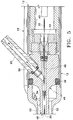
- Handpiece 10 of the present invention generally includes handpiece body 12 and operative tip 16.
- Body 12 generally includes external irrigation lumen 18 and aspiration fitting 20.
- Body 12 is similar in construction to well-known in the art phacoemulsification handpieces and may be made from plastic, titanium or stainless steel.
- operative tip 16 includes tip/cap sleeve 26, needle 28 and lumen 30.
- Sleeve 26 may be any suitable commercially available phacoemulsification tip/cap sleeve or sleeve 26 may be incorporated into other tubes as a multi-lumen tube.
- Needle 28 may be any commercially available hollow phacoemulsification cutting tip, such as the TURBOSONICS tip available from Alcon Laboratories, Inc., Fort Worth, Texas.
- Lumen 30 may be any suitably sized tubing to fit within needle 28, for example 29 gauge hypodermic needle tubing.
- lumen 30 is free on the distal end and connected to pumping chamber 42 on the proximal end.
- Lumen 30 and pumping chamber 42 may be sealed fluid tight by any suitable means having a relatively high melting point, such as silver solder.
- Fitting 44 holds lumen 30 within bore 48 of aspiration horn 46. Bore 48 communicates with fitting 20, which is journaled into horn 46 and sealed with O-ring seal 50 to form an aspiration pathway through horn 46 and out fitting 20.
- Horn 46 is held within body 12 by O-ring seal 56 to form irrigation lumen 52 which communicates with irrigation lumen 18 at port 54.
- pumping chamber 42 contains a relatively large pumping reservoir 43 that is sealed on both ends by electrodes 45 and 47. Electrical power is supplied to electrodes 45 and 47 by insulated wires 49 and 51, respectively.
- surgical fluid e.g. saline irrigating solution
- Electrical current preferably RFAC
- the surgical fluid boils. As the surgical fluid boils, it expands rapidly out of pumping chamber 42 through port 57 and into lumen 30 (check valve 53 prevents the expanding fluid from entering lumen 34).
- the expanding gas bubble pushes the surgical fluid in lumen 30 downstream of pumping chamber 42 forward. Subsequent pulses of electrical current form sequential gas bubbles that move surgical fluid down lumen 30.
- the size and pressure of the fluid pulse obtained by pumping chamber 42 can be varied by varying the length, timing and/or power of the electrical pulse sent to electrodes 45 and 47 and by varying the dimensions of reservoir 43.
- the surgical fluid may be preheated prior to entering pumping chamber 42. Preheating the surgical fluid will decrease the power required by pumping chamber 42 and/or increase the speed at which pressure pulses can be generated.
- any handpiece producing adequate pressure pulse force, temperature, rise time and frequency may also be used.
- any handpiece producing a pressure pulse force of between 0.03 grams and 3.0 grams, with a rise time of between 1 gram/sec. and 3,000 grams/sec and a frequency of between 1 Hz and 200 Hz may be used, with between 10 Hz and 100 Hz being most preferred.
- the pressure pulse force and frequency will vary with the hardness of the material being removed. For example, the inventors have found that a lower frequency with a higher pulse force is most efficient at debulking and removing the relatively hard nuclear material, with a higher frequency and lower pulse force being useful in removing softer epinuclear and conical material.
- Infusion pressure, aspiration flow rate and vacuum limit are similar to current phacoemulsification techniques.
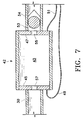
- the fluid in reservoir 143 in pumping chamber 142 may also be heated by the use of heating element 145 that is internal to reservoir 143.
- Heating element 145 may be, for example, a coil of 0.003 inch diameter stainless steel wire which is energized by power source 147.
- the size and pressure of the fluid pulse obtained by pumping chamber 142 can be varied by varying the length and timing of the electrical pulse sent to element 145 by control module 147 and by varying the dimensions of reservoir 143.
- control system 300 for use in operating handpiece 310 includes control module 347, power gain RF amplifier 312 and function generator 314. Power is supplied to RF amplifier 312 by DC power supply 316, which preferably is an isolated DC power supply operating at several hundred volts, but typically ⁇ 200 volts.
- Control module 347 may be any suitable microprocessor, micro controller, computer or digital logic controller and may receive input from operator input device 318.
- Function generator 314 provides the electric wave form in kilohertz to amplifier 312 and typically operates at round 450 KHz or above to help minimize corrosion.
- control module 347 receives input from surgical console 320.
- Console 320 may be any commercially available surgical control console such as the LEGACY® SERIES TWENTY THOUSAND® surgical system available from Alcon Laboratories, Inc., Fort Worth, Texas.
- Console 320 is connected to handpiece 310 through irrigation line 322 and aspiration line 324, and the flow through lines 322 and 324 is controlled by the user via footswitch 326.
- Irrigation and aspiration flow rate information in handpiece 310 is provided to control module 347 by console 320 via interface 328, which may be connected to the ultrasound handpiece control port on console 320 or to any other output port.
- Control module 347 uses footswitch 326 information provided by console 320 and operator input from input device 318 to generate two control signals 330 and 332.
- Signal 332 is used to operate pinch valve 334, which controls the surgical fluid flowing from fluid source 336 to handpiece 310. Fluid from fluid source 336 is heated in the manner described herein.
- Signal 330 is used to control function generator 314. Based on signal 330, function generator 314 provides a wave form at the operator selected frequency and amplitude determined by the position of footswitch 326 to RF amplifier 312 which is amplified to advance the powered wave form output to handpiece 310 to create heated, pressurized pulses of surgical fluid.
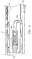
- surgical fluid may be supplied to pumping chamber 43 through lumen 34 or, as seen in FIG. 9, surgical fluid may be supplied to pumping chamber 243 through irrigation fluid lumen 234 which branches off main irrigation lumen 235 supplying cool surgical fluid to the operative site.
- irrigation fluid lumen 234 may be contained internally to handpiece 10.
- the pulse train duty cycle of the heated solution can be varied so that the total amount of heated solution introduced into the eye does not vary with the pulse frequency.
- the aspiration flow rate can be varied as a function of pulse frequency so that as pulse frequency increases aspiration flow rate increases proportionally.
Landscapes
- Health & Medical Sciences (AREA)
- Ophthalmology & Optometry (AREA)
- Heart & Thoracic Surgery (AREA)
- Surgery (AREA)
- Engineering & Computer Science (AREA)
- Biomedical Technology (AREA)
- Nuclear Medicine, Radiotherapy & Molecular Imaging (AREA)
- Vascular Medicine (AREA)
- Life Sciences & Earth Sciences (AREA)
- Animal Behavior & Ethology (AREA)
- General Health & Medical Sciences (AREA)
- Public Health (AREA)
- Veterinary Medicine (AREA)
- Surgical Instruments (AREA)
- External Artificial Organs (AREA)
Applications Claiming Priority (4)
| Application Number | Priority Date | Filing Date | Title |
|---|---|---|---|
| US09/090,433 US6080128A (en) | 1998-06-04 | 1998-06-04 | Liquefaction handpiece |
| US90433 | 1998-06-04 | ||
| US13040398A | 1998-08-06 | 1998-08-06 | |
| US130403 | 1998-08-06 |
Publications (1)
| Publication Number | Publication Date |
|---|---|
| EP0962204A1 true EP0962204A1 (de) | 1999-12-08 |
Family
ID=26782261
Family Applications (1)
| Application Number | Title | Priority Date | Filing Date |
|---|---|---|---|
| EP99201381A Withdrawn EP0962204A1 (de) | 1998-06-04 | 1999-05-03 | Steuerungssystem für ein Verflüssigungshandstück |
Country Status (5)
| Country | Link |
|---|---|
| EP (1) | EP0962204A1 (de) |
| JP (1) | JP2000005219A (de) |
| AU (2) | AU727194B2 (de) |
| BR (1) | BR9901770A (de) |
| CA (1) | CA2269263A1 (de) |
Cited By (5)
| Publication number | Priority date | Publication date | Assignee | Title |
|---|---|---|---|---|
| EP1199054A1 (de) * | 2000-10-17 | 2002-04-24 | Alcon Manufacturing Ltd. | Spitze für Verflüssigungshandstück |
| WO2002049552A3 (en) * | 2000-12-20 | 2003-03-27 | Alcon Inc | Solution for removing cataracts via liquefracture |
| US8377001B2 (en) | 2010-10-01 | 2013-02-19 | Abbott Laboratories | Feeding set for a peristaltic pump system |
| US8377000B2 (en) | 2010-10-01 | 2013-02-19 | Abbott Laboratories | Enteral feeding apparatus having a feeding set |
| US8689439B2 (en) | 2010-08-06 | 2014-04-08 | Abbott Laboratories | Method for forming a tube for use with a pump delivery system |
Families Citing this family (3)
| Publication number | Priority date | Publication date | Assignee | Title |
|---|---|---|---|---|
| US7811252B2 (en) * | 2006-05-17 | 2010-10-12 | Alcon Research, Ltd. | Dosage control device |
| TWI451862B (zh) * | 2007-10-09 | 2014-09-11 | Alcon Res Ltd | 用於眼睛注射的熱係數驅動藥丸尺寸 |
| JP2011120685A (ja) * | 2009-12-09 | 2011-06-23 | Univ Of Tsukuba | 処理装置 |
Citations (10)
| Publication number | Priority date | Publication date | Assignee | Title |
|---|---|---|---|---|
| US3589363A (en) | 1967-07-25 | 1971-06-29 | Cavitron Corp | Material removal apparatus and method employing high frequency vibrations |
| US4223676A (en) | 1977-12-19 | 1980-09-23 | Cavitron Corporation | Ultrasonic aspirator |
| US4246902A (en) | 1978-03-10 | 1981-01-27 | Miguel Martinez | Surgical cutting instrument |
| US4493694A (en) | 1980-10-17 | 1985-01-15 | Cooper Lasersonics, Inc. | Surgical pre-aspirator |
| US4515583A (en) | 1983-10-17 | 1985-05-07 | Coopervision, Inc. | Operative elliptical probe for ultrasonic surgical instrument and method of its use |
| US4589415A (en) | 1984-08-31 | 1986-05-20 | Haaga John R | Method and system for fragmenting kidney stones |
| US5203353A (en) * | 1989-10-24 | 1993-04-20 | Surgical Technologies, Inc. | Method of penetrating and working in the vitreous humor of the eye |
| EP0657152A2 (de) * | 1993-12-06 | 1995-06-14 | American Cyanamid Company | Verfahren und Vorrichtung zur Verhinderung einer hinteren Linsenkapseltrübung |
| US5616120A (en) * | 1995-02-06 | 1997-04-01 | Andrew; Mark S. | Method and apparatus for lenticular liquefaction and aspiration |
| WO1998025557A1 (en) * | 1996-12-11 | 1998-06-18 | Alcon Laboratories, Inc. | Liquefaction handpiece |
Family Cites Families (2)
| Publication number | Priority date | Publication date | Assignee | Title |
|---|---|---|---|---|
| US4597388A (en) * | 1983-12-15 | 1986-07-01 | Trutek Research, Inc. | Apparatus for removing cataracts |
| US5653692A (en) * | 1995-09-07 | 1997-08-05 | Innerdyne Medical, Inc. | Method and system for direct heating of fluid solution in a hollow body organ |
-
1999
- 1999-04-19 CA CA002269263A patent/CA2269263A1/en not_active Abandoned
- 1999-04-21 AU AU23875/99A patent/AU727194B2/en not_active Ceased
- 1999-04-21 AU AU23876/99A patent/AU734617B2/en not_active Ceased
- 1999-05-03 EP EP99201381A patent/EP0962204A1/de not_active Withdrawn
- 1999-06-02 BR BR9901770-9A patent/BR9901770A/pt not_active Application Discontinuation
- 1999-06-03 JP JP11156443A patent/JP2000005219A/ja active Pending
Patent Citations (10)
| Publication number | Priority date | Publication date | Assignee | Title |
|---|---|---|---|---|
| US3589363A (en) | 1967-07-25 | 1971-06-29 | Cavitron Corp | Material removal apparatus and method employing high frequency vibrations |
| US4223676A (en) | 1977-12-19 | 1980-09-23 | Cavitron Corporation | Ultrasonic aspirator |
| US4246902A (en) | 1978-03-10 | 1981-01-27 | Miguel Martinez | Surgical cutting instrument |
| US4493694A (en) | 1980-10-17 | 1985-01-15 | Cooper Lasersonics, Inc. | Surgical pre-aspirator |
| US4515583A (en) | 1983-10-17 | 1985-05-07 | Coopervision, Inc. | Operative elliptical probe for ultrasonic surgical instrument and method of its use |
| US4589415A (en) | 1984-08-31 | 1986-05-20 | Haaga John R | Method and system for fragmenting kidney stones |
| US5203353A (en) * | 1989-10-24 | 1993-04-20 | Surgical Technologies, Inc. | Method of penetrating and working in the vitreous humor of the eye |
| EP0657152A2 (de) * | 1993-12-06 | 1995-06-14 | American Cyanamid Company | Verfahren und Vorrichtung zur Verhinderung einer hinteren Linsenkapseltrübung |
| US5616120A (en) * | 1995-02-06 | 1997-04-01 | Andrew; Mark S. | Method and apparatus for lenticular liquefaction and aspiration |
| WO1998025557A1 (en) * | 1996-12-11 | 1998-06-18 | Alcon Laboratories, Inc. | Liquefaction handpiece |
Cited By (7)
| Publication number | Priority date | Publication date | Assignee | Title |
|---|---|---|---|---|
| EP1199054A1 (de) * | 2000-10-17 | 2002-04-24 | Alcon Manufacturing Ltd. | Spitze für Verflüssigungshandstück |
| EP1314409A3 (de) * | 2000-10-17 | 2003-07-16 | Alcon Manufacturing Ltd. | Zerflüssigungshandstück |
| WO2002049552A3 (en) * | 2000-12-20 | 2003-03-27 | Alcon Inc | Solution for removing cataracts via liquefracture |
| US7169755B2 (en) | 2000-12-20 | 2007-01-30 | Alcon, Inc. | Solution for removing cataracts via liquefracture |
| US8689439B2 (en) | 2010-08-06 | 2014-04-08 | Abbott Laboratories | Method for forming a tube for use with a pump delivery system |
| US8377001B2 (en) | 2010-10-01 | 2013-02-19 | Abbott Laboratories | Feeding set for a peristaltic pump system |
| US8377000B2 (en) | 2010-10-01 | 2013-02-19 | Abbott Laboratories | Enteral feeding apparatus having a feeding set |
Also Published As
| Publication number | Publication date |
|---|---|
| JP2000005219A (ja) | 2000-01-11 |
| AU2387699A (en) | 1999-12-16 |
| BR9901770A (pt) | 2000-01-18 |
| CA2269263A1 (en) | 1999-12-04 |
| AU727194B2 (en) | 2000-12-07 |
| AU2387599A (en) | 1999-12-23 |
| AU734617B2 (en) | 2001-06-21 |
Similar Documents
| Publication | Publication Date | Title |
|---|---|---|
| US6315755B1 (en) | Method of controlling a liquefracture handpiece | |
| US5989212A (en) | Pumping chamber for a liquefaction handpiece having a countersink electrode | |
| US6860868B1 (en) | Surgical handpiece | |
| US6648847B2 (en) | Method of operating a liquefracture handpiece | |
| US6589204B1 (en) | Method of operating a liquefracture handpiece | |
| US6080128A (en) | Liquefaction handpiece | |
| EP0962205B1 (de) | Spitze für ein Verflüssigungshandstück | |
| EP1199054B1 (de) | Verflüssigungshandstück | |
| US6589201B1 (en) | Liquefracture handpiece tip | |
| US6179805B1 (en) | Liquefracture handpiece | |
| US6579270B2 (en) | Liquefracture handpiece tip | |
| US6331171B1 (en) | Tip for a liquefracture handpiece | |
| AU727194B2 (en) | Control system for a liquefaction handpiece | |
| MXPA99005015A (en) | Control system for one piece manual delicuefacc | |
| MXPA99004983A (en) | One piece manual of licuefacc |
Legal Events
| Date | Code | Title | Description |
|---|---|---|---|
| PUAI | Public reference made under article 153(3) epc to a published international application that has entered the european phase |
Free format text: ORIGINAL CODE: 0009012 |
|
| AK | Designated contracting states |
Kind code of ref document: A1 Designated state(s): AT BE CH CY DE DK ES FI FR GB GR IE IT LI LU MC NL PT SE |
|
| AX | Request for extension of the european patent |
Free format text: AL;LT;LV;MK;RO;SI |
|
| 17P | Request for examination filed |
Effective date: 19991122 |
|
| RIN1 | Information on inventor provided before grant (corrected) |
Inventor name: THOE DAVID Inventor name: SALEHI AHMED Inventor name: MORELLO PHILIP P. Inventor name: COHEN, DONALD M. Inventor name: CAPETAN, THOMAS G. Inventor name: SUSSMAN,GLENN |
|
| RIN1 | Information on inventor provided before grant (corrected) |
Inventor name: THOE DAVID Inventor name: SALEHI AHMED Inventor name: MORELLO PHILIP P. Inventor name: COHEN, DONALD M. Inventor name: CAPETAN, THOMAS G. Inventor name: SUSSMAN,GLENN |
|
| AKX | Designation fees paid |
Free format text: AT BE CH CY DE DK ES FI FR GB GR IE IT LI LU MC NL PT SE |
|
| 17Q | First examination report despatched |
Effective date: 20030821 |
|
| GRAP | Despatch of communication of intention to grant a patent |
Free format text: ORIGINAL CODE: EPIDOSNIGR1 |
|
| STAA | Information on the status of an ep patent application or granted ep patent |
Free format text: STATUS: THE APPLICATION IS DEEMED TO BE WITHDRAWN |
|
| 18D | Application deemed to be withdrawn |
Effective date: 20040602 |