EP0962299A1 - Schmelzeventil - Google Patents
Schmelzeventil Download PDFInfo
- Publication number
- EP0962299A1 EP0962299A1 EP99109510A EP99109510A EP0962299A1 EP 0962299 A1 EP0962299 A1 EP 0962299A1 EP 99109510 A EP99109510 A EP 99109510A EP 99109510 A EP99109510 A EP 99109510A EP 0962299 A1 EP0962299 A1 EP 0962299A1
- Authority
- EP
- European Patent Office
- Prior art keywords
- melt
- valve
- plug
- outlet
- outlets
- Prior art date
- Legal status (The legal status is an assumption and is not a legal conclusion. Google has not performed a legal analysis and makes no representation as to the accuracy of the status listed.)
- Granted
Links
- 239000012815 thermoplastic material Substances 0.000 title 1
- 239000000155 melt Substances 0.000 claims abstract description 47
- 238000011144 upstream manufacturing Methods 0.000 claims abstract description 7
- 238000001914 filtration Methods 0.000 claims abstract 2
- 238000002844 melting Methods 0.000 claims description 8
- 230000008018 melting Effects 0.000 claims description 8
- 238000006073 displacement reaction Methods 0.000 claims description 3
- 230000001105 regulatory effect Effects 0.000 claims description 2
- 229920001169 thermoplastic Polymers 0.000 claims 2
- 239000004416 thermosoftening plastic Substances 0.000 claims 2
- 230000009969 flowable effect Effects 0.000 claims 1
- 238000007789 sealing Methods 0.000 description 9
- 238000000034 method Methods 0.000 description 4
- 241000287828 Gallus gallus Species 0.000 description 3
- 238000004140 cleaning Methods 0.000 description 3
- 238000005553 drilling Methods 0.000 description 3
- 230000000694 effects Effects 0.000 description 2
- 238000011010 flushing procedure Methods 0.000 description 2
- XLYOFNOQVPJJNP-UHFFFAOYSA-N water Substances O XLYOFNOQVPJJNP-UHFFFAOYSA-N 0.000 description 2
- 241001136792 Alle Species 0.000 description 1
- 230000015572 biosynthetic process Effects 0.000 description 1
- 239000003795 chemical substances by application Substances 0.000 description 1
- 238000010276 construction Methods 0.000 description 1
- 238000005516 engineering process Methods 0.000 description 1
- 238000001125 extrusion Methods 0.000 description 1
- 239000004519 grease Substances 0.000 description 1
- 238000010438 heat treatment Methods 0.000 description 1
- 238000009434 installation Methods 0.000 description 1
- 239000000314 lubricant Substances 0.000 description 1
- 238000005461 lubrication Methods 0.000 description 1
- 238000004519 manufacturing process Methods 0.000 description 1
- 239000000463 material Substances 0.000 description 1
- 238000012856 packing Methods 0.000 description 1
- 238000012545 processing Methods 0.000 description 1
- 230000005855 radiation Effects 0.000 description 1
- 238000004381 surface treatment Methods 0.000 description 1
- 230000001360 synchronised effect Effects 0.000 description 1
- 238000005496 tempering Methods 0.000 description 1
- 238000012549 training Methods 0.000 description 1
- 238000009423 ventilation Methods 0.000 description 1
- 238000013022 venting Methods 0.000 description 1
Images




Classifications
-
- B—PERFORMING OPERATIONS; TRANSPORTING
- B01—PHYSICAL OR CHEMICAL PROCESSES OR APPARATUS IN GENERAL
- B01D—SEPARATION
- B01D35/00—Filtering devices having features not specifically covered by groups B01D24/00 - B01D33/00, or for applications not specifically covered by groups B01D24/00 - B01D33/00; Auxiliary devices for filtration; Filter housing constructions
- B01D35/12—Devices for taking out of action one or more units of multi- unit filters, e.g. for regeneration
-
- B—PERFORMING OPERATIONS; TRANSPORTING
- B29—WORKING OF PLASTICS; WORKING OF SUBSTANCES IN A PLASTIC STATE IN GENERAL
- B29C—SHAPING OR JOINING OF PLASTICS; SHAPING OF MATERIAL IN A PLASTIC STATE, NOT OTHERWISE PROVIDED FOR; AFTER-TREATMENT OF THE SHAPED PRODUCTS, e.g. REPAIRING
- B29C48/00—Extrusion moulding, i.e. expressing the moulding material through a die or nozzle which imparts the desired form; Apparatus therefor
- B29C48/25—Component parts, details or accessories; Auxiliary operations
- B29C48/255—Flow control means, e.g. valves
-
- B—PERFORMING OPERATIONS; TRANSPORTING
- B29—WORKING OF PLASTICS; WORKING OF SUBSTANCES IN A PLASTIC STATE IN GENERAL
- B29C—SHAPING OR JOINING OF PLASTICS; SHAPING OF MATERIAL IN A PLASTIC STATE, NOT OTHERWISE PROVIDED FOR; AFTER-TREATMENT OF THE SHAPED PRODUCTS, e.g. REPAIRING
- B29C48/00—Extrusion moulding, i.e. expressing the moulding material through a die or nozzle which imparts the desired form; Apparatus therefor
- B29C48/25—Component parts, details or accessories; Auxiliary operations
- B29C48/36—Means for plasticising or homogenising the moulding material or forcing it through the nozzle or die
- B29C48/50—Details of extruders
- B29C48/69—Filters or screens for the moulding material
- B29C48/691—Arrangements for replacing filters, e.g. with two parallel filters for alternate use
-
- B—PERFORMING OPERATIONS; TRANSPORTING
- B29—WORKING OF PLASTICS; WORKING OF SUBSTANCES IN A PLASTIC STATE IN GENERAL
- B29C—SHAPING OR JOINING OF PLASTICS; SHAPING OF MATERIAL IN A PLASTIC STATE, NOT OTHERWISE PROVIDED FOR; AFTER-TREATMENT OF THE SHAPED PRODUCTS, e.g. REPAIRING
- B29C48/00—Extrusion moulding, i.e. expressing the moulding material through a die or nozzle which imparts the desired form; Apparatus therefor
- B29C48/03—Extrusion moulding, i.e. expressing the moulding material through a die or nozzle which imparts the desired form; Apparatus therefor characterised by the shape of the extruded material at extrusion
-
- Y—GENERAL TAGGING OF NEW TECHNOLOGICAL DEVELOPMENTS; GENERAL TAGGING OF CROSS-SECTIONAL TECHNOLOGIES SPANNING OVER SEVERAL SECTIONS OF THE IPC; TECHNICAL SUBJECTS COVERED BY FORMER USPC CROSS-REFERENCE ART COLLECTIONS [XRACs] AND DIGESTS
- Y10—TECHNICAL SUBJECTS COVERED BY FORMER USPC
- Y10T—TECHNICAL SUBJECTS COVERED BY FORMER US CLASSIFICATION
- Y10T137/00—Fluid handling
- Y10T137/5762—With leakage or drip collecting
-
- Y—GENERAL TAGGING OF NEW TECHNOLOGICAL DEVELOPMENTS; GENERAL TAGGING OF CROSS-SECTIONAL TECHNOLOGIES SPANNING OVER SEVERAL SECTIONS OF THE IPC; TECHNICAL SUBJECTS COVERED BY FORMER USPC CROSS-REFERENCE ART COLLECTIONS [XRACs] AND DIGESTS
- Y10—TECHNICAL SUBJECTS COVERED BY FORMER USPC
- Y10T—TECHNICAL SUBJECTS COVERED BY FORMER US CLASSIFICATION
- Y10T137/00—Fluid handling
- Y10T137/8593—Systems
- Y10T137/86493—Multi-way valve unit
- Y10T137/86509—Sequentially progressive opening or closing of plural ports
- Y10T137/86517—With subsequent closing of first port
- Y10T137/86533—Rotary
- Y10T137/86541—Plug
-
- Y—GENERAL TAGGING OF NEW TECHNOLOGICAL DEVELOPMENTS; GENERAL TAGGING OF CROSS-SECTIONAL TECHNOLOGIES SPANNING OVER SEVERAL SECTIONS OF THE IPC; TECHNICAL SUBJECTS COVERED BY FORMER USPC CROSS-REFERENCE ART COLLECTIONS [XRACs] AND DIGESTS
- Y10—TECHNICAL SUBJECTS COVERED BY FORMER USPC
- Y10T—TECHNICAL SUBJECTS COVERED BY FORMER US CLASSIFICATION
- Y10T137/00—Fluid handling
- Y10T137/8593—Systems
- Y10T137/86493—Multi-way valve unit
- Y10T137/86863—Rotary valve unit
- Y10T137/86871—Plug
Definitions
- the invention relates to a melt valve according to the preamble of claim 1.
- melt valves are primarily used in extrusion technology
- Large-area melt filters are used and as three-way valves have the task of the entry of the melt into the respective filter chamber and the exit from it Control the filter chamber.
- the two filter chambers are usually controlled by the two Three-way valves accomplished, which in the embodiments with simple Cock plug (cylindrical or conical), double cock plug (cylindrical or conical), Slide valves in plate construction or slide valves with cylindrical tappets be used.
- Slider valves have the disadvantage of an unfavorable flow of the melt and also long melt paths compared to the chick designs, which also causes problems posing while cleaning.
- both the melt inlet and the melt outlet are achieved by a single chick, which results in operational advantages, however the feed melt channels and melt lines are much longer and therefore the additional cleaning effort is increased.
- the present invention is therefore based on the object mentioned above Reduce disadvantages or avoid them entirely.
- melt valve should be developed so that on the one hand Melting paths are kept short for better cleaning options, and others are said to drive the cock plug largely outside of occurring Thermal radiation of the melt filter can be arranged.
- melt valve with a simple cock plug is used in which the melt occurs axially to the cock plug and the Radial melt outlet to it.
- the sealing of the relatively large melt channel is done with a special packing and an additional, tapered sealing lip on the inlet connector was released.
- This Sealing lip also has the property that it increases as the melt pressure rises Surface pressure on the sealing edge causes.
- the additional axial pressure that arises caught by a standard thrust bearing, which at the low Rotational movement with a unique high-temperature grease filling is permanently lubricated.
- the surface treatment comes through the narrow gaps between the plug and the housing a special treatment for the sliding surfaces. To do this, the chick with one Hard material coated in the micro range and the housing nitrided. This will be a good one Security against seizing and jamming of the plug in the housing is achieved.
- melt channel be twisted slightly the chick's current flow direction and the flow direction something in the cleaned filter already opens, causing the new filter to Plastic melt is flooded without interrupting the production process.
- melt channels be arranged that a partial coverage of both melt outlet channels is possible.
- the advantages of the present invention are short melting paths and the optimal ones lateral arrangement of the valve drive.
- valve actuator can be arranged in one area, in which the relatively high processing temperatures of the plastic melt hardly Have influence.
- melt valves according to the invention with laterally arranged valve drive both electrical or pneumatic, as well as by Manual drives can be operated with commercially available torque amplifiers.
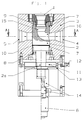
- Figure 1 shows the melt valve according to the invention in a preferred Embodiment, the plastic melt on the fixed flange or Melt inlet 1 enters the rotatable cock plug 2 and depending on the plug position the outlet opening 4 or 5 exits the housing 3 again.
- the chick gets over the Drive 6 and the gear means 14 rotated into the desired position, the Drive can be operated both by motor and by hand.
- the special seals 7 prevent the melt from escaping to the outside or into the Thrust bearing 8.
- the fixed flange has a sealing lip 9, which is designed so that the sealing effect between the sealing lip 9 and the cock plug 2 is increased with increasing melt pressure.
- the gap or the game between the tap plug 2 and the housing 3 is selected so that the plug 2 is straight can still be turned, but melt leakage through the gap is prevented. Should but the smallest amounts of melt penetrate into the gap are in front of and behind the Melt outlet 4, 5 leakage grooves 10 are provided in the tap plug 2, which the melt can lead to the outside via channels in the housing 3 without pressure.
- the stop disc 11 is firmly connected to the shaft 2a of the cock plug 2 and The rotary movements of the plug can be limited or adjusted using the adjusting screw 12. to adjust.
- the position of the plug can be determined using the disk of the angle of rotation sensor 13 read a scale, the scale can also be designed so that the position the chick via electronic displacement sensors or switching elements outside the entire valve can be displayed or registered.
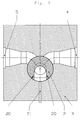
- Figure 2 shows the melt valve in a cross section along the line A-A through the Housing 3 and the cock plug 2.
- the melt enters the upstream side Section 15 of the cock plug 2 in and out through the outlet channels 4 or 5.
- the outlet channels 4 and 5 are not opposite, but under one Angles of less than 180 ° are arranged. First, this will make it necessary The angle of rotation of the chick is reduced and secondly, this results in a smaller one Twist of the chick 2 a partial coverage of the section 15 and downstream section 16 with both outlet channels 4, 5.
- the valve is heated via heating cartridges 17, the temperature being above Thermal sensor 18, which are inserted into the holes 18a, and over Temperature controller is regulated.
- FIG. 3 shows the melt valve in a cross section through the housing 3 and Cockerel chick 2 with chick 2 swiveled to receive water, here the Flood holes 20 firstly a defined amount of melt into the outlet channel 5 lets flow and thus starts the receiving process, and on the other hand in the outlet channel 4 Prevents the formation of dead corners as they melt these areas flush out.
- Figure 4 shows the melt valve in a cross section through the housing 3 and Cock plug 2 in which the plug 2 is pivoted in such a way that a ventilation or Flushing hole 21 is open and the outlet holes 4, 5 are closed.
- Figure 5 shows the melt valve in a cross section through the housing 3 and Rooster chick 2 in the position of chick 2, in which all channels 4, 5 and the bore 21 are closed.
- Figure 6 shows a cross section through the housing 3 and the cock plug 2 in one another embodiment of the valve with four outputs 4, 4a, 5, 5a, both the plug-side and the housing-side outputs 4, 4a, 5, 5a each by 90 ° are staggered.
- Figure 7 shows a cross section through the housing 3 and the cock plug 2 in one Another embodiment of the valve with four outputs 4, 4a, 5, 5a, two each Outputs 4, 4a and 5, 5a parallel to each other and the two pairs 4, 4a and 5, 5a are mutually offset by 180 °.
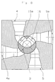
- FIG 8 shows a cross section through the housing 3 and the cock plug 2 in one Another embodiment of the valve with four outputs 4, 4a, 5, 5a and one Double outlet 16, 16a in the chick 2.
- the chick 2 connects its two Outlet channels 16, 16a each with two outlet channels 4, 4a, 5, 5a of the housing and thus the connections between the outlet channels 4, 4a and 4a, 5 and 5, 5a and 5a, 4 possible with the entry channel.
Landscapes
- Engineering & Computer Science (AREA)
- Mechanical Engineering (AREA)
- Chemical & Material Sciences (AREA)
- Chemical Kinetics & Catalysis (AREA)
- Multiple-Way Valves (AREA)
- Extrusion Moulding Of Plastics Or The Like (AREA)
- Filtration Of Liquid (AREA)
- Details Of Valves (AREA)
Abstract
Description
- 1
- Schmelzeeingang
- 2
- Hahnküken
- 2a
- Schaft
- 3
- Gehäuse
- 4
- Schmelzeausgang
- 4a
- Schmelzeausgang
- 5
- Schmelzeausgang
- 5a
- Schmelzeausgang
- 6
- Antrieb
- 7
- Spezialdichtung
- 8
- Drucklager
- 9
- Dichtlippe
- 10
- Leckagenut
- 11
- Anschlagscheibe
- 12
- Stellschraube
- 13
- Drehwinkelgeber
- 14
- getriebliche Mittel
- 15
- zuströmseitiger Abschnitt
- 16
- abströmseitiger Abschnitt
- 16a
- abströmseitiger Abschnitt
- 17
- Temperiermittel
- 18
- Thermofühler
- 18a
- Bohrung
- 19
- Leckagebohrung
- 20
- Vorflutbohrung
- 21
- Spühlbohrung
Claims (13)
- Schmelzeventil zum wahlweisen Zuführen eines fließfähig erschmolzenen thermoplastischen Kunststoffes zu wenigstens einem ersten und zweiten Schmelzefilter einer Anlage zum Herstellen flächenartiger thermoplastischer Produkte, mit einem im Ventilgehäuse (3) vorhandenen Schmelzeeingang (1) und wenigstens einem ersten Schmelzeausgang (4) und einem zweiten Schmelzeausgang (5), wobei die Verbindung zwischen dem Schmelzeeingang (1) und einem der Schmelzeausgänge (4,5) von einem im Ventilgehäuse (3) integrierten drehangetriebenen Hahnküken (2) mit wenigstens einem Strömungskanal hergestellt oder unterbrochen wird, wobei der wenigstens eine Strömungskanal des Hahnkükens einen zuströmseitigen Abschnitt (15) und einen abströmseitigen Abschnitt (16) besitzt, wobei das Ventil Mittel (17) zum Temperieren und Mittel (18) zur Regelung der Temperatur des Ventils besitzt, dadurch gekennzeichnet, dass der Schmelzeeingang (1) axial zum zuströmseitigen Abschnitt (15) des Hahnküken-Strömungskanals und die kükenseitigen Schmelzeausgänge (4,5) des Ventilgehäuses (3) radial zum abströmseitigen Abschnitt (16) des Hahnküken-Strömungskanals angeordnet sind und dass vom zuströmseitigen Abschnitt (15) Vorflutbohrungen (20) ausgehen, die bei vorgegebener Stellung des Hahnkükens gleichzeitig den ersten Schmelzeausgang (4) und den zweiten Schmelzeausgang (5) des Ventilgehäuses (3) mit dem zuströmseitigen Abschnitt (15) des Küken-Strömungskanals verbinden.
- Schmelzeventil nach Anspruch 1, dadurch gekennzeichnet, dass weitere Schmelzeausgänge (4a,5a) im Ventilgehäuse (3) angeordnet sind.
- Schmelzeventil nach Anspruch 1, und 2, dadurch gekennzeichnet, dass die Schmelzeausgänge (4,4a;5,5a) zueinander um 90° versetzt angeordnet sind.
- Schmelzeventil nach Anspruch 1 und 2, dadurch gekennzeichnet, dass die Schmelzeausgänge (4,4a) und (5,5a) jeweils ein Paar von Schmelzeausgängen bilden und wobei die Ausgänge der Paare parallel zueinander angeordnet sind, und die beiden Paare zueinander um 180 ° versetzt sind.
- Schmelzeventil nach Anspruch 1, dadurch gekennzeichnet, dass das Hahnküken (2) einen weiteren abströmseitigen Abschnitt (16a) besitzt, der zusammen mit dem abströmseitigen Abschnitt (16) je nach Position des Hahnkükens (2) zwei Schmelzeausgänge (4,4a;4,5a;4,5;5,5a;5,4a) miteinander verbindet.
- Schmelzeventil nach Anspruch 1, dadurch gekennzeichnet, dass das Hahnküken (2) einen Schaft (2a) besitzt, der über getriebliche Mittel (14) mit einem Antrieb (6) wirkverbunden ist.
- Schmelzeventil nach Anspruch 6, dadurch gekennzeichnet, dass der Antrieb (6) ein elektromotorischer Antrieb ist.
- Schmelzeventil nach Anspruch 1, dadurch gekennzeichnet, dass eine Anschlagscheibe (11) drehfest mit dem Schaft (2a) zwischen dem Hahnküken (2) und den getrieblichen Mitteln (14) verbunden ist.
- Schmelzeventil nach Anspruch 8, dadurch gekennzeichnet, dass die Drehbewegung der Anschlagscheibe (11) von einer Stellschraube (12) begrenzt ist.
- Schmelzeventil nach Anspruch 1, dadurch gekennzeichnet, dass elektronische Wegmessaufnehmer oder Schaltelemente vorhanden sind, die die Position des Hahnkükens (2) anzeigen und/oder registrieren.
- Schmelzeventil nach Anspruch 10, dadurch gekennzeichnet, dass der Wegmessaufnehmer ein mit dem Schaft (2a) drehfest verbundener Drehwinkelgeber (13) ist.
- Vorrichtung zur Schmelzefiltration mit einem ersten und einem zweiten Schmelzefilter, dadurch gekennzeichnet, dass deren Schmelzeeingänge mit einem nach den Merkmalen der Ansprüche 1 bis 11 ausgebildeten ersten Schmelzeventil in Wirkverbindung stehen und dass deren Schmelzeausgänge mit einem zweiten Schmelzeventil wirkverbunden sind, wobei dessen Schmelzeeingang wahlweise der Schmelzeausgang (4) oder (5) und der Schmelzeausgang der Schmelzeeingang (1) des nach den Merkmalen der Ansprüche 1 bis 11 ausgebildeten Schmelzeventils ist, und wobei ferner das zweite Schmelzeventil auf Vorflutbohrungen (20) verzichtet.
- Vorrichtung nach Anspruch 12, dadurch gekennzeichnet, dass der Schmelzeeingang (1) bzw. die Schmelzeeingänge (1), die Schmelzeausgänge (4,4a,5,5a) bzw. der Schmelzeausgang und der Antrieb (6) der betreffenden Hahnküken (2) in der horizontalen Ebene liegt (liegen).
Applications Claiming Priority (2)
| Application Number | Priority Date | Filing Date | Title |
|---|---|---|---|
| DE19824902A DE19824902A1 (de) | 1998-06-04 | 1998-06-04 | Schmelzeventil |
| DE19824902 | 1998-06-04 |
Publications (2)
| Publication Number | Publication Date |
|---|---|
| EP0962299A1 true EP0962299A1 (de) | 1999-12-08 |
| EP0962299B1 EP0962299B1 (de) | 2002-04-03 |
Family
ID=7869841
Family Applications (1)
| Application Number | Title | Priority Date | Filing Date |
|---|---|---|---|
| EP99109510A Expired - Lifetime EP0962299B1 (de) | 1998-06-04 | 1999-05-12 | Schmelzeventil |
Country Status (4)
| Country | Link |
|---|---|
| US (1) | US6196267B1 (de) |
| EP (1) | EP0962299B1 (de) |
| JP (1) | JP3200047B2 (de) |
| DE (2) | DE19824902A1 (de) |
Cited By (10)
| Publication number | Priority date | Publication date | Assignee | Title |
|---|---|---|---|---|
| EP1167844A2 (de) | 2000-06-21 | 2002-01-02 | GNEUSS KUNSTSTOFFTECHNIK GmbH | Mehrwegventil |
| DE102006050683A1 (de) * | 2006-10-24 | 2008-04-30 | Gneuß Kunststofftechnik GmbH | Vorrichtung zum gesteuerten Leiten einer Kunststoffschmelze |
| WO2016142244A3 (de) * | 2015-03-09 | 2016-12-29 | Dr. Collin Gmbh | Vorrichtung und verfahren zur prüfung von flüssigkeiten |
| EP3282245A1 (de) * | 2016-08-08 | 2018-02-14 | Blue Ocean Nova AG | Vorrichtung und verfahren zur analyse eines materialstroms |
| CN112601649A (zh) * | 2018-08-22 | 2021-04-02 | 格诺伊斯有限责任公司 | 用于高粘性介质的过滤装置 |
| CN115362324A (zh) * | 2020-01-21 | 2022-11-18 | 奥若泰克股份有限公司 | 阀 |
| EP4180200A1 (de) | 2021-11-12 | 2023-05-17 | Polymetrix AG | Verfahren zur herstellung und verarbeitung eines gemisches aus rezykliertem polyestermaterial und einem polyester-prepolymer aus einem polyester-herstellprozess |
| EP4180199A1 (de) | 2021-11-12 | 2023-05-17 | Polymetrix AG | Verfahren und vorrichtung zur herstellung und verarbeitung eines gemisches aus rezykliertem polyestermaterial und einem polyester-prepolymer aus einem polyester-herstellprozess |
| WO2023083802A1 (de) | 2021-11-12 | 2023-05-19 | Polymetrix Ag | Verfahren und vorrichtung zur herstellung und verarbeitung eines gemisches aus rezykliertem polyestermaterial und einem polyester-prepolymer aus einem polyester-herstellprozess |
| CN116497569A (zh) * | 2022-01-19 | 2023-07-28 | 海尔衣联生态科技(上海)有限公司 | 一种洗涤剂切换投放装置及洗涤设备 |
Families Citing this family (13)
| Publication number | Priority date | Publication date | Assignee | Title |
|---|---|---|---|---|
| DE10150796C2 (de) * | 2001-10-15 | 2003-08-07 | Collin Gmbh Dr | Vorrichtung zur Prüfung der Reinheit von Kunststoffschmelzen |
| DE10238901B3 (de) * | 2002-08-24 | 2004-06-03 | Zentes Unitex Gmbh | Hahnkükenventil |
| US20050006150A1 (en) * | 2003-07-07 | 2005-01-13 | Power Chokes, L.P. | Solids strainer system for a hydraulic choke |
| CN1956840B (zh) * | 2004-05-28 | 2010-11-24 | 倍耐力轮胎股份公司 | 用于制造轮胎的方法和装置 |
| JP4318623B2 (ja) * | 2004-10-25 | 2009-08-26 | 株式会社神戸製鋼所 | スクリーンチェンジャ |
| JP4800071B2 (ja) * | 2005-06-02 | 2011-10-26 | 株式会社クレハ | 回転式切換バルブ、切換バルブ装置、充填包装体製造装置及び充填包装体製造方法 |
| US11357966B2 (en) | 2015-04-23 | 2022-06-14 | B. Braun Medical Inc. | Compounding device, system, kit, software, and method |
| DE102015008637A1 (de) | 2015-07-03 | 2017-01-05 | Bb Engineering Gmbh | Schmelzeventil |
| DE102017208185A1 (de) | 2017-03-07 | 2018-09-13 | Robert Bosch Gmbh | Ventil zur Steuerung eines Fluidstroms |
| DE102018216149B4 (de) * | 2018-09-21 | 2023-05-25 | Fraunhofer-Gesellschaft zur Förderung der angewandten Forschung e.V. | Vorrichtung zur Beeinflussung des Volumenstroms von extrudiertem plastisch verformbaren Werkstoff |
| EP3854565A1 (de) * | 2020-01-21 | 2021-07-28 | Aurotec GmbH | Ventil und verfahren zum transport von fluiden |
| NO346374B1 (en) * | 2020-12-07 | 2022-06-27 | Astorplast As | A Device for Determining Offset Value of a Movable Valve Part |
| SE547376C2 (en) * | 2024-03-06 | 2025-07-22 | Valmet Oy | Separation valve, a system and a method of separating fibers from steam with the separation valve |
Citations (4)
| Publication number | Priority date | Publication date | Assignee | Title |
|---|---|---|---|---|
| GB1455611A (en) * | 1973-01-23 | 1976-11-17 | Zink Co Inc | Plug valve units for extrusion apparatus |
| DE4407941A1 (de) * | 1993-03-11 | 1994-09-15 | Aska Corp | Filtervorrichtung |
| US5462653A (en) * | 1994-02-15 | 1995-10-31 | Hills, Inc. | Apparatus for continuous polymer filtration |
| US5536399A (en) * | 1993-03-11 | 1996-07-16 | Aska Corporation | Filter device |
Family Cites Families (10)
| Publication number | Priority date | Publication date | Assignee | Title |
|---|---|---|---|---|
| US2702050A (en) | 1953-01-02 | 1955-02-15 | Stephen J Thomas | Two-way by-pass header valve |
| US3679060A (en) * | 1970-09-08 | 1972-07-25 | Xomox Corp | Duplex strainer construction |
| FR2148849A5 (de) * | 1971-07-30 | 1973-03-23 | Defontaine Freres Fils | |
| GB1420752A (en) * | 1972-04-19 | 1976-01-14 | Lucas Industries Ltd | Fluid control valve |
| SE373647B (sv) * | 1973-03-05 | 1975-02-10 | T L Henningsson | Regleranordning for strommande medier i anleggningar der en eller flera for matning med ett medium avsedda seriekopplade forbrukningsanordningar er anslutna till en mediekella |
| US3935108A (en) * | 1974-10-07 | 1976-01-27 | Parks-Cramer Company | Changeover valves with bypass and bent valving |
| US4156437A (en) * | 1978-02-21 | 1979-05-29 | The Perkin-Elmer Corporation | Computer controllable multi-port valve |
| DE3131281C2 (de) * | 1981-08-07 | 1993-10-21 | Fluidtech Gmbh | Vorrichtung zum getrennten Führen zweier Ströme, wahlweise nur eines Stromes, mindestens eines Mediums |
| DE3621746A1 (de) * | 1986-06-28 | 1988-01-21 | Hubert Skibowski | Absperrarmatur |
| DE19525062A1 (de) * | 1994-12-02 | 1996-06-05 | Richter Chemie Tech Itt Gmbh | Kugelhahn |
-
1998
- 1998-06-04 DE DE19824902A patent/DE19824902A1/de not_active Withdrawn
-
1999
- 1999-05-12 DE DE59901097T patent/DE59901097D1/de not_active Expired - Fee Related
- 1999-05-12 EP EP99109510A patent/EP0962299B1/de not_active Expired - Lifetime
- 1999-06-02 JP JP15512299A patent/JP3200047B2/ja not_active Expired - Fee Related
- 1999-06-02 US US09/324,242 patent/US6196267B1/en not_active Expired - Fee Related
Patent Citations (4)
| Publication number | Priority date | Publication date | Assignee | Title |
|---|---|---|---|---|
| GB1455611A (en) * | 1973-01-23 | 1976-11-17 | Zink Co Inc | Plug valve units for extrusion apparatus |
| DE4407941A1 (de) * | 1993-03-11 | 1994-09-15 | Aska Corp | Filtervorrichtung |
| US5536399A (en) * | 1993-03-11 | 1996-07-16 | Aska Corporation | Filter device |
| US5462653A (en) * | 1994-02-15 | 1995-10-31 | Hills, Inc. | Apparatus for continuous polymer filtration |
Cited By (15)
| Publication number | Priority date | Publication date | Assignee | Title |
|---|---|---|---|---|
| EP1167844A2 (de) | 2000-06-21 | 2002-01-02 | GNEUSS KUNSTSTOFFTECHNIK GmbH | Mehrwegventil |
| US6550497B2 (en) | 2000-06-21 | 2003-04-22 | Gneuss Kunststofftechnik Gmbh | Multipath rotary disc valve for distributing polymer plastics melts |
| DE102006050683A1 (de) * | 2006-10-24 | 2008-04-30 | Gneuß Kunststofftechnik GmbH | Vorrichtung zum gesteuerten Leiten einer Kunststoffschmelze |
| WO2016142244A3 (de) * | 2015-03-09 | 2016-12-29 | Dr. Collin Gmbh | Vorrichtung und verfahren zur prüfung von flüssigkeiten |
| EP3282245A1 (de) * | 2016-08-08 | 2018-02-14 | Blue Ocean Nova AG | Vorrichtung und verfahren zur analyse eines materialstroms |
| US10088417B2 (en) | 2016-08-08 | 2018-10-02 | Hochschule Reutlingen | Apparatus and method for analyzing a flow of material |
| CN112601649A (zh) * | 2018-08-22 | 2021-04-02 | 格诺伊斯有限责任公司 | 用于高粘性介质的过滤装置 |
| CN112601649B (zh) * | 2018-08-22 | 2022-11-22 | 格诺伊斯有限责任公司 | 用于高粘性介质的过滤装置 |
| CN115362324A (zh) * | 2020-01-21 | 2022-11-18 | 奥若泰克股份有限公司 | 阀 |
| CN115362324B (zh) * | 2020-01-21 | 2025-07-25 | 奥若泰克股份有限公司 | 阀 |
| EP4180200A1 (de) | 2021-11-12 | 2023-05-17 | Polymetrix AG | Verfahren zur herstellung und verarbeitung eines gemisches aus rezykliertem polyestermaterial und einem polyester-prepolymer aus einem polyester-herstellprozess |
| EP4180199A1 (de) | 2021-11-12 | 2023-05-17 | Polymetrix AG | Verfahren und vorrichtung zur herstellung und verarbeitung eines gemisches aus rezykliertem polyestermaterial und einem polyester-prepolymer aus einem polyester-herstellprozess |
| WO2023083802A1 (de) | 2021-11-12 | 2023-05-19 | Polymetrix Ag | Verfahren und vorrichtung zur herstellung und verarbeitung eines gemisches aus rezykliertem polyestermaterial und einem polyester-prepolymer aus einem polyester-herstellprozess |
| EP4450546A2 (de) | 2021-11-12 | 2024-10-23 | Polymetrix AG | Verfahren und vorrichtung zur herstellung und verarbeitung eines gemisches aus rezykliertem polyestermaterial und einem polyester-prepolymer aus einem polyester-herstellprozess |
| CN116497569A (zh) * | 2022-01-19 | 2023-07-28 | 海尔衣联生态科技(上海)有限公司 | 一种洗涤剂切换投放装置及洗涤设备 |
Also Published As
| Publication number | Publication date |
|---|---|
| US6196267B1 (en) | 2001-03-06 |
| JP2000205423A (ja) | 2000-07-25 |
| EP0962299B1 (de) | 2002-04-03 |
| JP3200047B2 (ja) | 2001-08-20 |
| DE19824902A1 (de) | 1999-12-30 |
| DE59901097D1 (de) | 2002-05-08 |
Similar Documents
| Publication | Publication Date | Title |
|---|---|---|
| EP0962299B1 (de) | Schmelzeventil | |
| DE69714675T2 (de) | Vorrichtung zum Schneiden und Formen eines kugelförmigen Körpers | |
| DE69005868T2 (de) | Einhebelmischventil mit Scheiben aus hartem Material, bei dem die bewegliche Scheibe um den Durchflussanschluss drehbar ist. | |
| EP0043076B1 (de) | Mischventil für Flüssigkeiten | |
| EP0305821B1 (de) | Vorrichtung zum Verschliessen einer Rohrabzweigung | |
| EP1626854B1 (de) | Anlage zum aufbereiten von stoffen | |
| DE2402172C2 (de) | Extruder | |
| DE69616047T2 (de) | Doppelscheibenrefiner | |
| EP1631434B1 (de) | Anlage zum aufbereiten von stoffen | |
| EP1577131B1 (de) | Strömungssteuereinrichtung zur Steuerung der Durchflussmenge eines fluiden Mediums durch einen Strömungskanal | |
| DE19537303A1 (de) | Vorrichtung zum Homogenisieren fließfähiger Stoffe | |
| DE2430527A1 (de) | Klappenventil | |
| EP0760254B1 (de) | Vorrichtung zum Homogenisieren fliessfähiger Stoffe | |
| DE69804211T2 (de) | Karusselltür | |
| EP1631435A1 (de) | Anlage zum aufbereiten von stoffen | |
| EP0513431B1 (de) | Vorrichtung zum Aufbereiten und Strangpressen von Werkstoffen | |
| DE3008832C2 (de) | ||
| DE3202915C2 (de) | Vorrichtung zum Mischen und/oder Homogenisieren eines fließfähigen Gutes | |
| DE102021101145A1 (de) | Verteilerventil für eine Kaffeemaschine, Kaffeemaschine mit einem solchen Verteilerventil, und Verfahren zum Verteilen von Medien auf Verbrauchsfunktionalitäten einer Kaffeemaschine | |
| CH660219A5 (de) | Einhebelmischventil. | |
| EP0463197A1 (de) | Trennbares Doppelventil | |
| DE1804314A1 (de) | Zwangsverdraengungsvorrichtung | |
| EP0745818A2 (de) | Vakuum-Trockenschrank | |
| AT502865B1 (de) | Vorrichtung zum mischen reaktiver kunststoffe | |
| DE2847614A1 (de) | Dreh-schieberverschluss fuer giesspfannen o.ae. |
Legal Events
| Date | Code | Title | Description |
|---|---|---|---|
| PUAI | Public reference made under article 153(3) epc to a published international application that has entered the european phase |
Free format text: ORIGINAL CODE: 0009012 |
|
| AK | Designated contracting states |
Kind code of ref document: A1 Designated state(s): BE CH DE FR GB IT LI NL |
|
| AX | Request for extension of the european patent |
Free format text: AL;LT;LV;MK;RO;SI |
|
| 17P | Request for examination filed |
Effective date: 20000215 |
|
| AKX | Designation fees paid |
Free format text: BE CH DE FR GB IT LI NL |
|
| 17Q | First examination report despatched |
Effective date: 20010125 |
|
| GRAG | Despatch of communication of intention to grant |
Free format text: ORIGINAL CODE: EPIDOS AGRA |
|
| GRAG | Despatch of communication of intention to grant |
Free format text: ORIGINAL CODE: EPIDOS AGRA |
|
| GRAH | Despatch of communication of intention to grant a patent |
Free format text: ORIGINAL CODE: EPIDOS IGRA |
|
| GRAH | Despatch of communication of intention to grant a patent |
Free format text: ORIGINAL CODE: EPIDOS IGRA |
|
| REG | Reference to a national code |
Ref country code: GB Ref legal event code: IF02 |
|
| GRAA | (expected) grant |
Free format text: ORIGINAL CODE: 0009210 |
|
| AK | Designated contracting states |
Kind code of ref document: B1 Designated state(s): BE CH DE FR GB IT LI NL |
|
| REG | Reference to a national code |
Ref country code: CH Ref legal event code: EP |
|
| REF | Corresponds to: |
Ref document number: 59901097 Country of ref document: DE Date of ref document: 20020508 |
|
| REG | Reference to a national code |
Ref country code: CH Ref legal event code: NV Representative=s name: R. A. EGLI & CO. PATENTANWAELTE |
|
| GBT | Gb: translation of ep patent filed (gb section 77(6)(a)/1977) |
Effective date: 20020701 |
|
| PLBE | No opposition filed within time limit |
Free format text: ORIGINAL CODE: 0009261 |
|
| STAA | Information on the status of an ep patent application or granted ep patent |
Free format text: STATUS: NO OPPOSITION FILED WITHIN TIME LIMIT |
|
| 26N | No opposition filed |
Effective date: 20030106 |
|
| PGFP | Annual fee paid to national office [announced via postgrant information from national office to epo] |
Ref country code: FR Payment date: 20050404 Year of fee payment: 7 |
|
| PGFP | Annual fee paid to national office [announced via postgrant information from national office to epo] |
Ref country code: DE Payment date: 20050419 Year of fee payment: 7 |
|
| PGFP | Annual fee paid to national office [announced via postgrant information from national office to epo] |
Ref country code: GB Payment date: 20050428 Year of fee payment: 7 |
|
| PGFP | Annual fee paid to national office [announced via postgrant information from national office to epo] |
Ref country code: BE Payment date: 20050429 Year of fee payment: 7 |
|
| PGFP | Annual fee paid to national office [announced via postgrant information from national office to epo] |
Ref country code: NL Payment date: 20050531 Year of fee payment: 7 |
|
| PGFP | Annual fee paid to national office [announced via postgrant information from national office to epo] |
Ref country code: CH Payment date: 20050831 Year of fee payment: 7 |
|
| PG25 | Lapsed in a contracting state [announced via postgrant information from national office to epo] |
Ref country code: GB Free format text: LAPSE BECAUSE OF NON-PAYMENT OF DUE FEES Effective date: 20060512 |
|
| PG25 | Lapsed in a contracting state [announced via postgrant information from national office to epo] |
Ref country code: LI Free format text: LAPSE BECAUSE OF NON-PAYMENT OF DUE FEES Effective date: 20060531 Ref country code: CH Free format text: LAPSE BECAUSE OF NON-PAYMENT OF DUE FEES Effective date: 20060531 Ref country code: BE Free format text: LAPSE BECAUSE OF NON-PAYMENT OF DUE FEES Effective date: 20060531 |
|
| PGFP | Annual fee paid to national office [announced via postgrant information from national office to epo] |
Ref country code: IT Payment date: 20060531 Year of fee payment: 8 |
|
| PG25 | Lapsed in a contracting state [announced via postgrant information from national office to epo] |
Ref country code: NL Free format text: LAPSE BECAUSE OF NON-PAYMENT OF DUE FEES Effective date: 20061201 Ref country code: DE Free format text: LAPSE BECAUSE OF NON-PAYMENT OF DUE FEES Effective date: 20061201 |
|
| REG | Reference to a national code |
Ref country code: CH Ref legal event code: PL |
|
| GBPC | Gb: european patent ceased through non-payment of renewal fee |
Effective date: 20060512 |
|
| NLV4 | Nl: lapsed or anulled due to non-payment of the annual fee |
Effective date: 20061201 |
|
| REG | Reference to a national code |
Ref country code: FR Ref legal event code: ST Effective date: 20070131 |
|
| BERE | Be: lapsed |
Owner name: *LINDAUER DORNIER G.M.B.H. Effective date: 20060531 |
|
| PG25 | Lapsed in a contracting state [announced via postgrant information from national office to epo] |
Ref country code: FR Free format text: LAPSE BECAUSE OF NON-PAYMENT OF DUE FEES Effective date: 20060531 |
|
| PG25 | Lapsed in a contracting state [announced via postgrant information from national office to epo] |
Ref country code: IT Free format text: LAPSE BECAUSE OF NON-PAYMENT OF DUE FEES Effective date: 20070512 |