EP0962310A2 - Machine pour la fabrication de carton ondulé simple à grande vitesse avec injection de vapeur - Google Patents
Machine pour la fabrication de carton ondulé simple à grande vitesse avec injection de vapeur Download PDFInfo
- Publication number
- EP0962310A2 EP0962310A2 EP99304163A EP99304163A EP0962310A2 EP 0962310 A2 EP0962310 A2 EP 0962310A2 EP 99304163 A EP99304163 A EP 99304163A EP 99304163 A EP99304163 A EP 99304163A EP 0962310 A2 EP0962310 A2 EP 0962310A2
- Authority
- EP
- European Patent Office
- Prior art keywords
- web
- steam
- liner
- medium
- elongated
- Prior art date
- Legal status (The legal status is an assumption and is not a legal conclusion. Google has not performed a legal analysis and makes no representation as to the accuracy of the status listed.)
- Withdrawn
Links
- 238000010793 Steam injection (oil industry) Methods 0.000 title abstract description 5
- 239000000853 adhesive Substances 0.000 claims abstract description 35
- 230000001070 adhesive effect Effects 0.000 claims abstract description 35
- 239000003292 glue Substances 0.000 claims abstract description 23
- XLYOFNOQVPJJNP-UHFFFAOYSA-N water Substances O XLYOFNOQVPJJNP-UHFFFAOYSA-N 0.000 claims abstract description 13
- 238000000034 method Methods 0.000 claims abstract description 8
- 238000010411 cooking Methods 0.000 claims abstract description 3
- 238000006664 bond formation reaction Methods 0.000 claims description 13
- 238000004519 manufacturing process Methods 0.000 claims description 9
- 239000007788 liquid Substances 0.000 claims description 5
- 238000012545 processing Methods 0.000 claims description 5
- 238000010438 heat treatment Methods 0.000 claims description 3
- 238000007599 discharging Methods 0.000 claims description 2
- 229920002472 Starch Polymers 0.000 abstract description 14
- 239000008107 starch Substances 0.000 abstract description 14
- 235000019698 starch Nutrition 0.000 abstract description 14
- 230000018044 dehydration Effects 0.000 abstract description 13
- 238000006297 dehydration reaction Methods 0.000 abstract description 13
- 239000002002 slurry Substances 0.000 abstract description 6
- 230000015572 biosynthetic process Effects 0.000 abstract description 5
- 239000008187 granular material Substances 0.000 abstract description 4
- 230000002028 premature Effects 0.000 abstract description 3
- 230000001737 promoting effect Effects 0.000 abstract 1
- 239000002131 composite material Substances 0.000 description 6
- 238000009833 condensation Methods 0.000 description 3
- 230000005494 condensation Effects 0.000 description 3
- 230000004323 axial length Effects 0.000 description 2
- 238000010276 construction Methods 0.000 description 2
- 238000002347 injection Methods 0.000 description 2
- 239000007924 injection Substances 0.000 description 2
- 230000004048 modification Effects 0.000 description 2
- 238000012986 modification Methods 0.000 description 2
- 239000011087 paperboard Substances 0.000 description 2
- 238000011144 upstream manufacturing Methods 0.000 description 2
- 229920002261 Corn starch Polymers 0.000 description 1
- 238000004026 adhesive bonding Methods 0.000 description 1
- 230000002411 adverse Effects 0.000 description 1
- 239000008120 corn starch Substances 0.000 description 1
- 229940099112 cornstarch Drugs 0.000 description 1
- 230000002542 deteriorative effect Effects 0.000 description 1
- 238000001035 drying Methods 0.000 description 1
- 239000003595 mist Substances 0.000 description 1
- 238000012360 testing method Methods 0.000 description 1
- 238000012546 transfer Methods 0.000 description 1
Images

Classifications
-
- B—PERFORMING OPERATIONS; TRANSPORTING
- B31—MAKING ARTICLES OF PAPER, CARDBOARD OR MATERIAL WORKED IN A MANNER ANALOGOUS TO PAPER; WORKING PAPER, CARDBOARD OR MATERIAL WORKED IN A MANNER ANALOGOUS TO PAPER
- B31F—MECHANICAL WORKING OR DEFORMATION OF PAPER, CARDBOARD OR MATERIAL WORKED IN A MANNER ANALOGOUS TO PAPER
- B31F1/00—Mechanical deformation without removing material, e.g. in combination with laminating
- B31F1/20—Corrugating; Corrugating combined with laminating to other layers
- B31F1/24—Making webs in which the channel of each corrugation is transverse to the web feed
- B31F1/26—Making webs in which the channel of each corrugation is transverse to the web feed by interengaging toothed cylinders cylinder constructions
- B31F1/28—Making webs in which the channel of each corrugation is transverse to the web feed by interengaging toothed cylinders cylinder constructions combined with uniting the corrugated webs to flat webs ; Making double-faced corrugated cardboard
- B31F1/2845—Details, e.g. provisions for drying, moistening, pressing
- B31F1/2872—Spraying devices, e.g. for moistening purposes; Lubricating devices
-
- B—PERFORMING OPERATIONS; TRANSPORTING
- B31—MAKING ARTICLES OF PAPER, CARDBOARD OR MATERIAL WORKED IN A MANNER ANALOGOUS TO PAPER; WORKING PAPER, CARDBOARD OR MATERIAL WORKED IN A MANNER ANALOGOUS TO PAPER
- B31F—MECHANICAL WORKING OR DEFORMATION OF PAPER, CARDBOARD OR MATERIAL WORKED IN A MANNER ANALOGOUS TO PAPER
- B31F1/00—Mechanical deformation without removing material, e.g. in combination with laminating
- B31F1/20—Corrugating; Corrugating combined with laminating to other layers
- B31F1/24—Making webs in which the channel of each corrugation is transverse to the web feed
- B31F1/26—Making webs in which the channel of each corrugation is transverse to the web feed by interengaging toothed cylinders cylinder constructions
- B31F1/28—Making webs in which the channel of each corrugation is transverse to the web feed by interengaging toothed cylinders cylinder constructions combined with uniting the corrugated webs to flat webs ; Making double-faced corrugated cardboard
- B31F1/2845—Details, e.g. provisions for drying, moistening, pressing
- B31F1/285—Heating or drying equipment
-
- Y—GENERAL TAGGING OF NEW TECHNOLOGICAL DEVELOPMENTS; GENERAL TAGGING OF CROSS-SECTIONAL TECHNOLOGIES SPANNING OVER SEVERAL SECTIONS OF THE IPC; TECHNICAL SUBJECTS COVERED BY FORMER USPC CROSS-REFERENCE ART COLLECTIONS [XRACs] AND DIGESTS
- Y10—TECHNICAL SUBJECTS COVERED BY FORMER USPC
- Y10T—TECHNICAL SUBJECTS COVERED BY FORMER US CLASSIFICATION
- Y10T156/00—Adhesive bonding and miscellaneous chemical manufacture
- Y10T156/10—Methods of surface bonding and/or assembly therefor
- Y10T156/1002—Methods of surface bonding and/or assembly therefor with permanent bending or reshaping or surface deformation of self sustaining lamina
- Y10T156/1007—Running or continuous length work
- Y10T156/1016—Transverse corrugating
- Y10T156/1021—Treating material of corrugated lamina or dry adhesive thereon to render tacky
-
- Y—GENERAL TAGGING OF NEW TECHNOLOGICAL DEVELOPMENTS; GENERAL TAGGING OF CROSS-SECTIONAL TECHNOLOGIES SPANNING OVER SEVERAL SECTIONS OF THE IPC; TECHNICAL SUBJECTS COVERED BY FORMER USPC CROSS-REFERENCE ART COLLECTIONS [XRACs] AND DIGESTS
- Y10—TECHNICAL SUBJECTS COVERED BY FORMER USPC
- Y10T—TECHNICAL SUBJECTS COVERED BY FORMER US CLASSIFICATION
- Y10T156/00—Adhesive bonding and miscellaneous chemical manufacture
- Y10T156/10—Methods of surface bonding and/or assembly therefor
- Y10T156/1002—Methods of surface bonding and/or assembly therefor with permanent bending or reshaping or surface deformation of self sustaining lamina
- Y10T156/1025—Methods of surface bonding and/or assembly therefor with permanent bending or reshaping or surface deformation of self sustaining lamina to form undulated to corrugated sheet and securing to base with parts of shaped areas out of contact
Definitions
- the invention relates to the manufacturing of corrugated paperboard, and more particularly to the use of steam injection to allow higher production speeds without sacrificing adhesive bonding quality.
- a single facer apparatus is used to flute the medium web, to apply adhesive (e.g. starch adhesives) to the flute tips on one of the faces of the medium web, and to bring a liner web into contact with glue lines on the flute tips of the medium web with the application of heat downstream to form the initial bond.
- adhesive e.g. starch adhesives
- Many manufacturers in the art use high-pressure (e.g. 20,000 lbs. of force) at the bonding nip where the liner web is introduced to the flute tips on the medium web. Others use less pressure at the bonding nip.
- the assignee of this application produces a single facer in which the liner roll introducing the liner web to the fluted medium web is spaced apart from the fluted surface of the bonding roll.
- the present invention involves the use of steam injection at the convergence of the webs to improve the formation of adhesive bonds between the liner web and the flute tips on the medium web, especially at relatively high production speeds (e.g. 1300 feet per minute). It is particularly useful on single facers that do not have a high pressure bonding nip.
- the starch adhesive When applied to the flute tips on the medium web, the starch adhesive consists of a slurry of starch granules in water (e.g. an aqueous-based starch adhesive). In order to achieve optimum bond strength, it is desirable that the water and starch granule slurry first gelatinize into a viscous gel. In order to gelatinize the starch adhesive, the adhesive slurry must be heated to a temperature of at least 150°F for a sufficient amount of time. It is therefore known in the art to preheat the liner web to promote gelatinization of the adhesive, preferably to about 180° to 212°F. The viscous gel does not have significant bond strength until dehydration occurs. However, if dehydration occurs prematurely before gelatinization, the resulting bond will be poor.
- the initial green bonds formed on the single facer between the liner web and the flute tips of the medium web have sufficient strength to withstand further processing downstream in the corrugator.
- green bond formation begins immediately at about 200°F, substantial dehydration of the glue line and adjoining web surfaces must occur before adequate green bond strength is realized.
- the medium web is heated on the bonding roll preferably to about 215°F to facilitate dehydration and formation of the green bond.
- the bonding roll surface temperature should be at about 375°F or more. As more heat is added to evaporate moisture, the bond strength continues to increase. A fully cured bond is finally obtained when most of the water is evaporated (e.g. approximately 80%).
- the invention promotes high speed corrugator production without sacrificing adhesive quality by injecting a steam cloud between the fluted medium web on a single facer bonding roll and the liner web directly at the line along which the webs converge.
- the direct application of the steam cloud provides additional heat to the glue lines on the flute tips without causing premature dehydration to facilitate appropriate gelatinization of the adhesive, and also promote sufficient green bond formation between the flute tips on the medium web and the liner web as the composite single face web is carried downstream on the bonding roll.
- Steam injection is a particularly effective means for additional heat because of the latent heat associated with the phase change of steam upon condensation.
- injected steam heating can be controlled virtually instantaneously.
- the invention is preferably implemented using an elongated steam shower tube that extends generally parallel with the bonding roll and the liner roll.
- the elongated tube has a plurality of aligned steam discharge openings configured to produce a steam cloud that is directed at the line at which the webs converge.
- the aligned steam discharge holes are located approximately 2 to 3 inches from the convergence line, thus allowing the steam cloud discharged from the aligned openings to be accurately directed at the convergence line. It has been found that applying the steam upstream of the convergence line significantly deteriorates the strength of the resulting green bond.
- the steam cloud consist of dry steam.
- Dry steam is steam in which the ratio by weight of water vapor in the steam to the combination of water vapor and suspended liquid droplets together is substantially high.
- the preferred construction for a dry steam shower includes an elongated outer tube that receives the steam from the steam source, and an inner tube mounted within the outer tube.
- the inner tube includes steam inlet openings to allow the flow of steam into the inner tube.
- the dimensions of the steam inlet openings is limited, however, to restrict the flow of steam into the inner tube such that the steam pressure within the inner tube is lower than the steam pressure in the outer tube.
- the inner tube contains the aligned steam discharge openings that are directed at the web convergence iine. In the embodiment shown in the drawings, the aligned steam discharge openings on the inner tube are exposed through a slot on the outer tube.
- the temperature of the steam within the inner tube is lower than the temperature of the steam within the outer tube because the pressure of the steam within the inner tube is lower than the pressure of the steam within the outer tube.
- the steam within the outer tube therefore heats the wall of the inner tube to a temperature greater than the temperature of the steam located within the inner tube. Because the wall of the inner tube has a temperature greater than the temperature of the steam within the inner tube, little or no condensation occurs within the inner tube and the amount of suspended liquid droplets in steam discharged from the shower is insignificant.
- steam shower have an outlet that is located downstream of the aligned steam discharge openings.
- a normally closed valve is located at the outlet which is closed during normal operation so that steam flows through the aligned steam discharge openings. Upon system start-up, the valve is opened such that steam provided to the tube clears the tube of condensed water. This is important upon start-up so that a slug of condensed water does not blast against the webs and tear or otherwise damage the webs.
- the liner roll does not apply pressure against the bonding roll at the convergence of the two webs.
- a single facer is disclosed in U.S. Patent Application No. 08/740,726, by Carl Marschke, filed on November 1, 1996, and entitled "Low Pressure Single Facer" (See, e.g., page 10).
- the invention is likely to be useful in single facers having a low-pressure bonding nip or other configurations in which additional heat at the web convergence line are desired.
- the invention may be useful to promote bonding on other corrugator components, such as injecting dry steam on a double backer.
- the liner web is maintained in substantial contact with the flute tips on the medium web by the tension of the liner web as the composite web is carried on the heated bonding roll.
- the liner web is maintained in contact with the flute tips on the medium web on the bonding roll for an amount of time at least sufficient to allow appropriate green bond formation from the gelatinized adhesive.
- the bonding roll is heated at approximately 375° to promote effective formation of the green bond.
- the invention is particularly useful for facilitating proper gelatinization of adhesive and green bond formation at high corrugator production speeds when using starch-based adhesives (e.g. cornstarch adhesive). It should further be appreciated by those skilled in the art that the invention is not limited to conventional starch-based adhesives. Any adhesive whose performance is affected by the phenomena of drying and/or heating could likely be employed in variations of the present invention.
- starch-based adhesives e.g. cornstarch adhesive
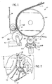
- Fig. 1 is a side elevational view of a corrugator single facer having a steam shower that injects a steam cloud between a corrugated medium web and a liner web at the convergence of the webs as in accordance with the invention.
- Fig. 2 is a detailed view of the area outlined by line 2-2 in Fig. 1.
- Fig. 3 is a sectional view taken along line 3-3 in Fig. 2.
- Fig. 4 is a view taken along line 4-4 in Fig. 2.
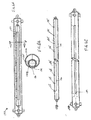
- Fig. 5 is a view showing the preferred construction of a steam shower used in accordance with the invention.
- Figs. 6a through 6c show a dry steam shower in accordance with the invention.
- a single facer 10 operates to form a composite single face web 12 from a medium web 14 and a liner web 16, which function is generally characteristic of prior art single facers.
- the incoming medium web 14 is directed into a corrugating nip 18 defined by inter-engaging flutes on the circumference of a bonding roll 20 and on the circumference of a corrugating roll 22.
- the medium web 14 is deformed in the corrugating nip 18 to provide the characteristic flutes of the medium web 14a.
- a detailed description of the inter-engaging flutes on the circumference of the bonding roll 20 and on the circumference of the corrugating roll 22 is disclosed in copending U.S. Patent Application No. 09/044,561, by Carl R.
- the corrugating roll 22 is relatively small compared to the bonding roll 20. Deflection of the corrugating roll 22 is preferably controlled by a plurality of belted backing roll arrangements 23. Each arrangement 23 includes a pressure belt 23b around idler rollers 23i which are pneumatically mounted to the single facer structure. The belt 23b may be fluted to match the fluted surface of the small corrugating roll 22.
- each of the backing roll arrangements 23 includes its own pneumatic cylinder, each backing roll arrangement can be configured to operate independently such that the backing force is varied along the axial length of the small diameter corrugating roll 22.
- the fluted medium web 14a wraps around the corrugated surface of the bonding roll 20.
- the bonding roll 20 carries the fluted medium web 14 around its circumference
- the flute tips of the corrugated medium web 14a are contacted by a rotating glue applicator roll 24.
- the glue applicator roll 24 applies a layer of aqueous starch-based adhesive to the flute tips on the medium web 14a to create continuous glue lines 27 (See Figs. 2-4) along the flute tips.
- the aqueous starch-based adhesive is preferably stored in a glue pan 31 prior to being applied to the flute tips by the rotating glue application roller 24.
- the aqueous starch-based adhesive typically consists as a water and starch granule slurry in the glue pan 31, and when the adhesive is initially applied to create continuous glue lines along the flute tips on the medium web 14a.
- the liner web 16 is brought tangentially into contact with the glued flute tips of the corrugated medium web 14a at a web bonding convergence line 28.
- the liner web 16 is wrapped around the circumference of a liner roll 26.
- the liner roll 26 is preferably preheated to heat the liner web 16 to a temperature sufficiently higher than the gelatinization temperature of the adhesive (i.e., above about 150°F), preferably to about 180° and 212°F.
- preheating plates can be used upstream of the liner roll 26.
- any method of conventional preheating whether by roll, hot air, steam shower, radiant energy, or other known source, may be employed in preheating the liner web 16, or it may be found that preheating is not required in particular applications.
- the liner roll 26 is spaced from the fluted outer surface of the bonding roll 20 by a distance sufficient to preclude any significant nip pressure on the joined webs 14a and 16.
- the preheated liner roll 26 is preferably spaced by a distance at least as great as the combined thickness of the liner web 16 and the corrugated medium web 14a.
- the glue line 27 at the flute tips on the medium web 14a are not squeezed to displace moisture prematurely from the adhesive.
- the composite webs 14a, 16 are subsequently carried on the bonding roll 20 together until the composite single face web 12 is transferred from the bonding roll 20 for further processing downstream in the corrugator.
- the bonding roll 20 is preferably heated to approximately 375°F to promote dehydration of the adhesive and formation of a green bond having sufficient strength to withstand further processing downstream in the corrugator.
- a variable wrap arm device such as disclosed in copending U.S. Patent Application No. 09/044,516, filed on March 19, 1998, by Carl R.
- Marschke entitled “Single Facer With Small Intermediate Corrugating Roll And Variable Wrap Arm Device", incorporated herein by reference, may be used to lengthen the time in which the composite webs 14a, 16 are in contact with the bonding roll 20 subsequent to convergence of the webs on the bonding roll 20.
- a steam shower 30 injects a steam cloud 36 between the fluted medium web 14a on the bonding roll 20 and the liner web 16 introduced from the liner roll 26.
- the steam cloud 36 is injected directly at the web convergence line 28.
- the steam shower 30 provides additional heat and moisture to the glue lines 27 on the flute tips at the web convergence line 28, but does not promote premature dehydration.
- the steam cloud 36 therefore promotes proper gelatinization of the adhesive between the flute tips on the corrugated medium web 14a and the liner web 16, as well as efficient green bond formation thereafter.
- a typical form for the steam shower 30 is an elongated tube 32 mounted generally in parallel with the bonding roll 20 and the liner roll 26.
- the elongated tube 32 preferably extends transversely across the single facer 10 at least the width of the medium web 14a on the bonding roll 20.
- the elongated tube 32 is mounted in place using mounting bracket 33.
- the tube 32 is secured tightly within the walls 35 of the bracket 33.
- the mounting bracket 33 may be constructed integrally with a water-cooled glue shield as is shown in the drawings.
- the elongated steam shower tube 32 contains a plurality of aligned steam discharge openings 34 that are directed at the web convergence line 28, see Fig. 2.
- the preferred inside diameter of the elongated tube 32 is approximately 0.5 to 1.5 inches, and the preferred outside diameter of the tube 32 is approximately .75 to 1.75 inches. It is desirable that the diameter of the aligned steam discharge openings be sufficiently small, preferably 0.04 to 0.05 inches, to provide a steam cloud or mist without substantial kinetic energy that is likely to deteriorate the applied glue lines 27 on the flute tips before bonding. It is also desirable that the steam cloud 36, Fig. 3, be relatively uniform over the transverse width of the web. Therefore, the aligned steam discharge openings 34 are preferably spaced apart evenly about 1/4 to 1/3 of an inch from each other along the length of the tube 32.
- Steam is provided to the elongated steam shower tube 32 from a source 38, Fig. 5, of pressurized steam, for example 150 psia.
- a variable flow control valve 40 can be provided in a steam supply conduit 42 between the steam source 38 and the steam shower 32 to adjust the steam pressure within the tube 32 as appropriate.
- the elongated steam shower tube 32 preferably includes an outlet 43 that is located downstream of the aligned steam discharge openings 34.
- a normally closed valve 44 is located at the outlet 43. The valve 44 is closed during normal operation so that steam flows through the aligned steam discharge openings 34. On the other hand, the valve 44 is opened at system start-up to clear the elongated steam shower tube 32 of condensed water, thereby preventing a slug of condensed water from discharging through the openings 34 against the webs 16, 14a.
- the dry steam shower 132 in Figs. 6a through 6c includes an outer elongated tube 132a and an inner elongated tube 132b.
- the outer elongated tube 132a includes an elongated open slot 134 that provides an opening directed at the web convergence line 28.
- the inner tube 132b is completely enclosed except for steam inlets 135 and the aligned steam discharge openings 136.
- the inner tube 132b is mounted within the outer tube 132a such that the aligned steam discharge openings 136b in the inner tube 132b are exposed through the elongated slot 134 in the outer tube 132a.
- the orientation and size of the aligned steam discharge openings 136 are preferably the same or similar to the embodiment shown in Figs. 2 through 5.
- the inner tube 132b is mounted such that the steam inlets 135 are located at the top of the tube 132b.
- the size and the configuration of the steam inlets 135 is limited to restrict the flow of steam into the inner steam diameter within the inner tube 132b, e.g. openings 135 having a 1/4 inch diameter and spaced apart 6 inches along the tube 132b have been found suitable for some applications.
- the inlet openings 135 provide a restricted flow area such that the pressure of the steam within the inner tube 132 is less than the pressure outside of the tube 132.
- the temperature of the steam inside of the inner tube 132b is less than the temperature of the steam outside of the inner tube 132b.
- the steam outside of the inner tube 132b heats the wall of the inner tube 132b. It is therefore unlikely for condensation to form within the inner tube 132b.
- the steam discharged from the shower 132 is substantially dry and does not contain a significant amount of suspended liquid water droplets.
- the invention promotes proper cooking conditions for accelerated gelatinization of the adhesive, while at the same time does not interfere with subsequent dehydration, which is needed to produce green bond strength sufficient for further processing of the newly bonded single face web 12 on the corrugator.
- Tests have shown that the injection of the steam cloud 36 towards the web convergence line 28 improves single facer bonding performance such that single facers achieving suitable bonding performance at a maximum speed of approximately 1000 feet per minute can obtain the same or better bonding quality at speeds greater than or equal to 1300 feet per minute when using the invention as disclosed.
Landscapes
- Engineering & Computer Science (AREA)
- Mechanical Engineering (AREA)
- Machines For Manufacturing Corrugated Board In Mechanical Paper-Making Processes (AREA)
- Laminated Bodies (AREA)
Applications Claiming Priority (2)
| Application Number | Priority Date | Filing Date | Title |
|---|---|---|---|
| US09/088,215 US6171427B1 (en) | 1998-06-01 | 1998-06-01 | High speed corrugator single facer with steam injection |
| US88215 | 1998-06-01 |
Publications (2)
| Publication Number | Publication Date |
|---|---|
| EP0962310A2 true EP0962310A2 (fr) | 1999-12-08 |
| EP0962310A3 EP0962310A3 (fr) | 2000-08-23 |
Family
ID=22210069
Family Applications (1)
| Application Number | Title | Priority Date | Filing Date |
|---|---|---|---|
| EP99304163A Withdrawn EP0962310A3 (fr) | 1998-06-01 | 1999-05-28 | Machine pour la fabrication de carton ondulé simple à grande vitesse avec injection de vapeur |
Country Status (5)
| Country | Link |
|---|---|
| US (1) | US6171427B1 (fr) |
| EP (1) | EP0962310A3 (fr) |
| JP (1) | JP2000025131A (fr) |
| KR (1) | KR20000005769A (fr) |
| CA (1) | CA2273566A1 (fr) |
Cited By (2)
| Publication number | Priority date | Publication date | Assignee | Title |
|---|---|---|---|---|
| FR2797853A1 (fr) * | 1999-08-31 | 2001-03-02 | Miniplus | Support alimentaire et procede de fabrication |
| WO2023072911A1 (fr) * | 2021-10-29 | 2023-05-04 | Bhs Corrugated Maschinen- Und Anlagenbau Gmbh | Dispositif d'éjection de vapeur |
Families Citing this family (8)
| Publication number | Priority date | Publication date | Assignee | Title |
|---|---|---|---|---|
| US20030056886A1 (en) * | 2001-09-21 | 2003-03-27 | Schmidt Stephen R. | Apparatus and method for manufacturing corrugated boards |
| DE10330751A1 (de) * | 2003-07-07 | 2005-02-10 | Windmöller & Hölscher Kg | Bodenlegevorrichtung für Papiersäcke |
| US7150100B2 (en) * | 2004-07-09 | 2006-12-19 | Armstrong International, Inc. | Method of forming a jacketed steam distribution tube |
| JP2010241079A (ja) | 2009-04-09 | 2010-10-28 | Mitsubishi Heavy Ind Ltd | 段ボールシート加熱方法及び装置 |
| ES2932369T3 (es) | 2018-04-17 | 2023-01-18 | Intpro Llc | Aparato para producir un producto corrugado |
| JP7240880B2 (ja) * | 2019-01-17 | 2023-03-16 | 三菱重工機械システム株式会社 | シート加湿装置および方法並びに段ボールシートの製造装置 |
| CN115782305B (zh) * | 2022-11-29 | 2024-08-30 | 浙江骏驰纸制品有限公司 | 一种瓦楞纸板压平装置及其使用方法 |
| CN116714319B (zh) * | 2023-08-08 | 2023-10-13 | 德州春祥包装制品有限公司 | 一种强化瓦楞纸板粘合设备 |
Family Cites Families (20)
| Publication number | Priority date | Publication date | Assignee | Title |
|---|---|---|---|---|
| US2102937A (en) | 1935-07-26 | 1937-12-21 | Stein Hall Mfg Co | Plyboard adhesive |
| US2487647A (en) | 1945-11-27 | 1949-11-08 | Samuel M Langston Co | Heating system for corrugating machines |
| US2987105A (en) | 1957-12-24 | 1961-06-06 | Koppers Co Inc | Method and apparatus for producing corrugated paperboard |
| US3097994A (en) * | 1961-02-03 | 1963-07-16 | Kimberly Clark Co | Steaming device for a papermaking machine |
| US3434901A (en) * | 1965-10-23 | 1969-03-25 | West Virginia Pulp & Paper Co | Method for manufacturing corrugated board |
| US3394041A (en) | 1966-07-13 | 1968-07-23 | West Virginia Pulp & Paper Co | Gelling adhesive in a corrugated paper making machine |
| US3690981A (en) | 1970-03-02 | 1972-09-12 | Owens Illinois Inc | Process for the manufacture of laminated article |
| US3857514A (en) * | 1970-09-03 | 1974-12-31 | Armstrong Machine Works | Steam dispersion manifold |
| US3849224A (en) * | 1972-07-21 | 1974-11-19 | Westvaco Corp | Water resistant corrugated paperboard |
| US3922129A (en) * | 1974-05-10 | 1975-11-25 | William V Mcdonald | Corrugating system employing controllable steam shower |
| US4278486A (en) | 1976-04-29 | 1981-07-14 | Schrader Edward H | Method and apparatus for corrugating paperboard |
| US4134781A (en) | 1977-05-03 | 1979-01-16 | Key Chemicals, Inc. | Method for controlling warp in the manufacture of corrugated paperboard |
| US4348250A (en) * | 1980-02-20 | 1982-09-07 | Masson Scott Thrissell Engineering | Single facer for making single faced corrugated material |
| JPS5915066B2 (ja) * | 1980-07-22 | 1984-04-07 | アイキ工業株式会社 | 段ボ−ル紙を製造する方法および装置 |
| JPS6013535A (ja) * | 1983-07-05 | 1985-01-24 | アイキ工業株式会社 | 段ボ−ル紙製造装置 |
| FR2555101B1 (fr) | 1983-11-17 | 1987-10-23 | Martin Sa | Procede et dispositif de fabrication d'une bande de carton ondule |
| JPS60203430A (ja) | 1984-02-20 | 1985-10-15 | 森紙業株式会社 | 段ボ−ルシ−ト貼合わせ方法および装置 |
| JPS60174635A (ja) * | 1984-02-20 | 1985-09-07 | 森紙業株式会社 | 段ボ−ルシ−ト製造機の糊付け装置 |
| US5244518A (en) * | 1990-11-02 | 1993-09-14 | Stickle Steam Specialties Co. Inc. | Corrugated board manufacturing apparatus and process including precise web moisture and temperature control |
| JP2592183B2 (ja) * | 1990-12-25 | 1997-03-19 | 三菱重工業株式会社 | 片面段ボール製造機 |
-
1998
- 1998-06-01 US US09/088,215 patent/US6171427B1/en not_active Expired - Fee Related
-
1999
- 1999-05-28 EP EP99304163A patent/EP0962310A3/fr not_active Withdrawn
- 1999-05-31 KR KR1019990019891A patent/KR20000005769A/ko not_active Withdrawn
- 1999-05-31 CA CA002273566A patent/CA2273566A1/fr not_active Abandoned
- 1999-06-01 JP JP11154351A patent/JP2000025131A/ja active Pending
Cited By (2)
| Publication number | Priority date | Publication date | Assignee | Title |
|---|---|---|---|---|
| FR2797853A1 (fr) * | 1999-08-31 | 2001-03-02 | Miniplus | Support alimentaire et procede de fabrication |
| WO2023072911A1 (fr) * | 2021-10-29 | 2023-05-04 | Bhs Corrugated Maschinen- Und Anlagenbau Gmbh | Dispositif d'éjection de vapeur |
Also Published As
| Publication number | Publication date |
|---|---|
| KR20000005769A (ko) | 2000-01-25 |
| CA2273566A1 (fr) | 1999-12-01 |
| EP0962310A3 (fr) | 2000-08-23 |
| JP2000025131A (ja) | 2000-01-25 |
| US6171427B1 (en) | 2001-01-09 |
Similar Documents
| Publication | Publication Date | Title |
|---|---|---|
| US8398802B2 (en) | Method for moisture and temperature control in corrugating operation | |
| US6171427B1 (en) | High speed corrugator single facer with steam injection | |
| AU709283B2 (en) | Improved low pressure single facer | |
| US20120024476A1 (en) | Method and device for heating corrugated cardboard sheet | |
| US4316755A (en) | Adhesive metering device for corrugating processes | |
| FI109774B (fi) | Aaltopahvin valmistusmenetelmä | |
| US20060225830A1 (en) | Method and apparatus for producing a corrugated product | |
| US6155320A (en) | Method and apparatus for injecting steam at a single facer bonding nip | |
| US6089296A (en) | Pre-conditioning of a medium web during the fabrication of corrugated paperboard | |
| EP0748992A2 (fr) | Système de séchage assisté par dépression pour une bande de matériau | |
| JP2765759B2 (ja) | 張力下での接着によって片面段ボールのシートを製造する機械および方法 | |
| US5360506A (en) | Idler roll having improved thermal characteristics | |
| US5897824A (en) | Surface heating for a corrugated medium web | |
| US5996246A (en) | Edge seal for vacuum preheater | |
| US6048429A (en) | Production of double wall corrugated web | |
| US3394041A (en) | Gelling adhesive in a corrugated paper making machine | |
| US6921450B2 (en) | Soft contact roll for a single facer | |
| EP1115558A1 (fr) | Prechauffeur de carton ondule simple face | |
| KR100397809B1 (ko) | 강화된 골심을 갖는 골심 골판지 및 그 성형장치와성형방법 | |
| MXPA97008344A (es) | Aparato para formar una cara sencilla con baja presion, mejorado | |
| JPS6213181B2 (fr) | ||
| JP2001198994A (ja) | 両面段ボールの製造方法 |
Legal Events
| Date | Code | Title | Description |
|---|---|---|---|
| PUAI | Public reference made under article 153(3) epc to a published international application that has entered the european phase |
Free format text: ORIGINAL CODE: 0009012 |
|
| AK | Designated contracting states |
Kind code of ref document: A2 Designated state(s): DE ES FR GB IT |
|
| AX | Request for extension of the european patent |
Free format text: AL;LT;LV;MK;RO;SI |
|
| PUAL | Search report despatched |
Free format text: ORIGINAL CODE: 0009013 |
|
| AK | Designated contracting states |
Kind code of ref document: A3 Designated state(s): AT BE CH CY DE DK ES FI FR GB GR IE IT LI LU MC NL PT SE |
|
| AX | Request for extension of the european patent |
Free format text: AL;LT;LV;MK;RO;SI |
|
| 17P | Request for examination filed |
Effective date: 20010221 |
|
| AKX | Designation fees paid |
Free format text: DE ES FR GB IT |
|
| RAP1 | Party data changed (applicant data changed or rights of an application transferred) |
Owner name: MARQUIP, LLC |
|
| STAA | Information on the status of an ep patent application or granted ep patent |
Free format text: STATUS: THE APPLICATION HAS BEEN WITHDRAWN |
|
| 18W | Application withdrawn |
Withdrawal date: 20010706 |