EP0962335A1 - Entfernbare Blätterringe oder Spiralbinder - Google Patents
Entfernbare Blätterringe oder Spiralbinder Download PDFInfo
- Publication number
- EP0962335A1 EP0962335A1 EP99401327A EP99401327A EP0962335A1 EP 0962335 A1 EP0962335 A1 EP 0962335A1 EP 99401327 A EP99401327 A EP 99401327A EP 99401327 A EP99401327 A EP 99401327A EP 0962335 A1 EP0962335 A1 EP 0962335A1
- Authority
- EP
- European Patent Office
- Prior art keywords
- sheet
- orifice
- binding
- border
- orifices
- Prior art date
- Legal status (The legal status is an assumption and is not a legal conclusion. Google has not performed a legal analysis and makes no representation as to the accuracy of the status listed.)
- Withdrawn
Links
- 239000011230 binding agent Substances 0.000 title claims abstract description 8
- 230000027455 binding Effects 0.000 claims description 46
- 238000009739 binding Methods 0.000 claims description 46
- 238000003780 insertion Methods 0.000 claims description 4
- 230000037431 insertion Effects 0.000 claims description 4
- 230000001788 irregular Effects 0.000 claims description 3
- 238000004519 manufacturing process Methods 0.000 claims description 3
- 238000000034 method Methods 0.000 claims description 3
- 230000004075 alteration Effects 0.000 claims description 2
- 238000012423 maintenance Methods 0.000 claims description 2
- 239000011159 matrix material Substances 0.000 description 5
- 239000000463 material Substances 0.000 description 4
- 210000000056 organ Anatomy 0.000 description 2
- 238000011144 upstream manufacturing Methods 0.000 description 2
- 230000006866 deterioration Effects 0.000 description 1
- 239000000126 substance Substances 0.000 description 1
Images


Classifications
-
- B—PERFORMING OPERATIONS; TRANSPORTING
- B42—BOOKBINDING; ALBUMS; FILES; SPECIAL PRINTED MATTER
- B42F—SHEETS TEMPORARILY ATTACHED TOGETHER; FILING APPLIANCES; FILE CARDS; INDEXING
- B42F3/00—Sheets temporarily attached together involving perforations; Means therefor; Sheet details therefor
- B42F3/003—Perforated or punched sheets
Definitions
- the present invention relates to a removable sheet having a soft, flexible border comprising spaced aligned orifices, intended to be associated with a binding comprising mounting members such as rings or turns, a set comprising the combination of such a sheet and a binding, a process mounting such an assembly.
- This device alone is not intended to maintain rigid to the mounting members, as required for example for a suspended filing system. It is then planned an additional fastening device such as a classic perforation cooperating with a ring.
- the invention proposes to remedy these difficulties while allowing easy handling of the sheets, including if they are heavy enough, as in the case of albums by photographs.
- the invention relates to a removable sheet comprising a flexible flexible border, which comprises a free edge and orifices, the border defining a longitudinal direction and being able to cooperate by the orifices with a closed, typically ring or sirals, the orifices being spaced and aligned along the free edge, the sheet being such that, for each orifice, the border includes a through cutout that connects the orifice at the free edge and has two close edges and substantially opposite, the cutouts allowing insertion and manual removal without alteration of the slip in binding without opening it, maintaining the slip being insured despite a force appreciably perpendicular to the direction of binding.
- each cut is substantially in contact and define a space typically between 0.1 and 1 mm, or spaced less than half the distance apart larger dimension of the orifice.
- the holes in the border are either all identical, or at least two different types.
- the holes in the border are either spaced at regular intervals, or at irregular intervals.
- Each cut extends either in a direction substantially perpendicular to the longitudinal direction, either inclined relative to this direction.
- each hole includes, on the edge side free of the border, an opening in which the cutting.
- a cut ends in an orifice, according to or offset with respect to its axis of symmetry.
- the border is of substantially constant width and includes two edges, a first edge corresponding to the edge free from the sheet and a second facing edge, substantially parallel, or non-parallel, the distance between the opposite ends aligned with the edges of the cutout then being higher on the side of the opening of the orifice, or on the free edge side of the sheet.
- the cut extends essentially along a direction either straight or non-straight, and in this second case it includes several straight sections connected between them, or it is wavy.
- the orifices are generally circular or oblong, but can be of different shapes for example square or rectangular.
- the distance between two cuts along the longitudinal axis is generally greater than 1.5 times the largest hole size, preferably 1.5 to 2 times this length.
- the length of the edges of a cutout is at least 0.5 times the largest dimension of the hole, usually 0.5 to 1 times this length.
- Each orifice is capable of receiving either a ring of binding, i.e. at least two rings, one apart the other and opposite in the opening according to its direction longitudinal.
- the invention relates to a binding or the like cooperating with a sheet as described previously.
- the invention relates to a set including the combination of a sheet as described previously and a binding as described previously.
- the invention relates to a product production of a sheet as described above.
- the invention relates to a method mounting an assembly as described above.
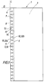
- the sheet 1 of the invention generally forms a surface plane. It is intended to be mounted along a binding 2.
- the sheet 1 comprises a border 4 soft and flexible typically plastic or analogous, associated with a matrix 3.
- the matrix 3 can be in a different material, for example rigid, in a single holding, or removable from the border 4.
- the border 4 has two edges, namely a free edge 5 corresponding to the free edge of the sheet, and an edge 6 in gaze, adjacent to the matrix 3.
- the border 4 defines a direction L and includes between its two edges 5, 6 a plurality of holes 7, which are aligned, and spaced along the direction L.
- edges 5 and 6 are straight. We can imagine that they are not in other embodiments.
- the border 4 has cutouts 8, one per orifice 7, connecting each orifice 7 to the free edge 5.
- each cut is delimited by two cutting edges 9, 10, substantially opposite.
- Edge 9a two ends, 9a and 9b.
- Edge 9 ends in its end 9 a at the free edge 5, and at its end 9b at the orifice 7.
- the edge 10 has two ends 10a and 10b. The edge 10 ends at its end 10a at free edge 5, and its end 10b to the orifice 7.
- each orifice 7 includes an opening A delimited by the ends 9b and 10b of the cutting edges 9 and 10.
- This part flexible 11 is T-shaped, and includes a shaft 12 and two wings 13, 14.
- the shaft 12 extends from the edge free 5 as far as between the two orifices 7. In the embodiment of Figure 3, the shaft 12 is rectangular.
- the two wings 13, 14 are located on either side of the shank 12, between this shank 12 and two cutouts 8.
- a shank 12 has a part 12a close to the free edge and a part 12b between the two orifices.
- the border 4 thus comprises a plurality of parts flexible 11 in a T shape. Each flexible part 11 is bounded by two cutouts 8. Parts 11 are contiguous and aligned along the border in the direction longitudinal.
- Figures 4a, 4b, 4c illustrate three modes of realization of the shape of the cut.
- the cut is straight in Figure 4a.
- the cut has several rectilinear sections 22, connected to each other, forming a broken line, in Figure 4b.
- the cut presents corrugations 23, forming a wavy line, in the figure 4c.
- FIGS 5a, 5b illustrate two embodiments of the direction of cutting according to the invention.
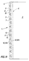
- the cutting direction is perpendicular to the direction L in FIG. 4a. It is tilted as on Figures 6a and 6b, at an angle ⁇ with the direction longitudinal L, between 45 and 135 degrees usually.
- the cutting has two edges 9, 10 which are not parallel.
- the ends 9a and 10a on the free edge side are spaced a distance apart d1.
- the ends 9b and 10b are spaced apart by a distance d2.
- the distance d1 is greater than d2 in FIG. 6a, equal to d2 in figure 4a, less than d2, in figure 6b.
- the ends 9b and 10b of the cutting edges are located on the side and on the other side of the axis of symmetry P of the orifice.
- the orifices 7 are all identical, circular. They are aligned according to the direction L and spaced from each other at intervals regular.
- the border 4 comprises circular orifices 7 and oblong orifices, the largest dimension is in direction L.
- the orifices 7 can also be in particular square or rectangular.
- the largest dimension of an orifice 7 is not necessarily in the longitudinal direction L.
- the matrix 3 of sheet 1 generally consists of several layers, thermally welded together, chemical or ultrasonic.
- the sheet includes two layers C1, C2 welded together to form a pocket.
- the pouch is open on one side only while in figure 14 it is open to two sides.
- the sheet 1 comprises three layers C1, C2, C3, of which a C3 forms a screen, the other two being plated with on both sides so as to form compartments.
- the screen layer is for example of semi-rigid material.
- the sheets 1 are designed to be inserted in a binder 2 of a binder 24 conventional or similar.
- the user can turn the sheets 1 one by one such that conventionally the pages of a workbook.
- the upstream direction of page flow corresponds to turning the pages from right to left from the beginning to the end of the workbook.
- the downstream direction corresponds to turning them in the direction opposite.
- a binding 2 comprises rigid mounting members 15 or semi-rigid. These mounting members 15 are spaced apart and aligned in a direction R. These are typically rings or S turns. The stiffness of binding 2 is higher than that of the border 4.
- the mounting members 15 are generally of substantially circular section ( Figure 9) or rectangular ( Figure 10).
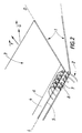
- Binding 2 is a circular binding. Each turn forms an unclosed hollow ring, part of which protruding 18 forming a closed loop is turned towards the downstream direction of the opening of the pages, and a reentrant part 19 open, facing the sail portion 18 is oriented upstream of opening the pages.
- the turns thus defined are linked together by arcs 20 oriented substantially in the direction L.
- the orifices 7 are circular. Each orifice 7 receives a coil S. The cutouts are opposite the coil S.
- the orifices 7 are oblong and their largest dimension is in the direction L.
- Each orifice 7 receives two turns 16, 17, spaced from each other so as to be close the outline of the orifice 7 for better maintenance of the sheet 1.
- This last variant involves alternation according to the direction L of arcs 20a located opposite the cutouts of the sheet and arcs 20b located opposite the shafts 12 of flexible parts 11.
- the length of the arcs 20b can be high, up to two to three times the length of the orifice in the direction L.
- the two turns of the same orifice can thus be very far apart from each other.
- This device provides both good support and easy insertion of the sheets on two turns at the same time time, through a single orifice. And all the more that the bindings may be intended for sheets of large dimension and contain objects of significant weight.
- the number of mounting members 15 can be very variable. For example, for an A4-size loose leaf, a ten for a filing cabinet or similar to twenty for a spiral binding.
- Each mounting member 15 includes an internal contour 15a and an external contour 15b.
- the mounting of the sheet 1 in the binding 2 consists first of all align the border 4 of the sheet 1 with the binding 2, making the directions L and R coincide. For that, we put opposite the orifices 7 and the contour 15b of the organs of mounting 15. Then manually exert a force, to each orifice, on the stems 12 of the flexible parts 11 (see figure 12) so as to insert them one by one in the binding.
- the force is exerted essentially perpendicular to the direction L. Thanks to the flexibility of border material, cutting edges 9, 10 move apart and the flexible wings 13, 14 deform and are positioned on the side of the contour 15a of the organs of mounting 15 allowing the flexible parts 11 to be inserted in the binding. The wings 13, 14 then return in their initial flat position.
- the cutouts 8 thus allow the mounting of the sheet 1 on the mounting members 15 without opening the binding 2.
- the user is not obliged to start with a either end of border 4 of sheet 1.
- the sheet 1 is strongly maintained thanks to this arrangement, even if a force F tensile substantially in the direction D transverse to the longitudinal direction is applied.
- a wide variety of sets are obtained by combining sheets and a binding as described in particular according to: format and number of sheets, type of matrix used, the elements contained in the sheets (photographs, computer diskettes), the mode of use (laid flat, vertically, suspended).
- the binding can belong to a filing cabinet, to a diary or to any other device having means for mounting the leaflet as described above.
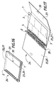
- a plurality of sheets 1 is associated with a Binding 2 and forms the pages of a workbook 24.
- This workbook 24 includes a cover 25 consisting of two flaps 26, 27. These flaps 26, 27 have a border 28 with orifices 7 able to cooperate with the binding, but their border 28 does not have cutouts 8. These flaps are in semi-rigid material to protect the sheets 1 of the filing cabinet 24.
- the flap 27 forms the cover top, the flap 28 the under cover.
- the flap 28 includes a fold 29 suitable for being attached to shutter 26 by a system of the type velcro 30, which allows the filing cabinet to be closed.
- the holes 7 are made aligned and spaced in the border 4, then the cutouts 8 starting from the free edge 5 and leading to the orifices.
Landscapes
- Sheet Holders (AREA)
Applications Claiming Priority (2)
| Application Number | Priority Date | Filing Date | Title |
|---|---|---|---|
| FR9806900 | 1998-06-02 | ||
| FR9806900A FR2779094B1 (fr) | 1998-06-02 | 1998-06-02 | Feuillets amovibles pour reliures a anneaux ou spirales |
Publications (1)
| Publication Number | Publication Date |
|---|---|
| EP0962335A1 true EP0962335A1 (de) | 1999-12-08 |
Family
ID=9526931
Family Applications (1)
| Application Number | Title | Priority Date | Filing Date |
|---|---|---|---|
| EP99401327A Withdrawn EP0962335A1 (de) | 1998-06-02 | 1999-06-02 | Entfernbare Blätterringe oder Spiralbinder |
Country Status (2)
| Country | Link |
|---|---|
| EP (1) | EP0962335A1 (de) |
| FR (1) | FR2779094B1 (de) |
Cited By (9)
| Publication number | Priority date | Publication date | Assignee | Title |
|---|---|---|---|---|
| EP1216843A3 (de) * | 2000-12-06 | 2003-04-23 | Bertelsmann Kalender & Promotion Service GmbH | Wandkalender mit einem lösbaren Befestigungselement |
| EP1967385A2 (de) | 2007-03-09 | 2008-09-10 | Visu-AD | Multifunktionselement eines Systems zur Füllung bzw. Lagerung eines Artikels |
| FR2943948A1 (fr) * | 2009-04-02 | 2010-10-08 | Papeteries Hamelin | Fiche d'annotation d'informations repositionnable dans un produit de papeterie, tel qu'un cahier |
| US20150048610A1 (en) * | 2013-08-13 | 2015-02-19 | ACCO Brands Corporation | Device with Quick-Attach Feature |
| US20160347108A1 (en) * | 2015-05-27 | 2016-12-01 | Ec Design Llc | Interchangeable stationery articles and methods of using same |
| US20170021661A1 (en) * | 2014-02-03 | 2017-01-26 | Holdham | Fact sheet intended for being inserted between two pages of a stationery product, such as a notebook |
| CN109263350A (zh) * | 2018-10-26 | 2019-01-25 | 安徽瀚洋纸品印刷有限公司 | 一种方便拆装的活页笔记本 |
| USD1097791S1 (en) | 2023-02-06 | 2025-10-14 | Decolin Inc. | Shower curtain ring |
| USD1097792S1 (en) | 2023-02-06 | 2025-10-14 | Decolin Inc. | Shower curtain ring |
Citations (2)
| Publication number | Priority date | Publication date | Assignee | Title |
|---|---|---|---|---|
| FR699383A (fr) * | 1929-08-03 | 1931-02-13 | Kalamazoo Sa Des Ets | Perfectionnements aux registres ou relieurs à feuillets mobiles |
| FR871385A (fr) * | 1941-04-05 | 1942-04-22 | Reliure Spirale | Perfectionnements aux reliures à feuilles amovibles |
-
1998
- 1998-06-02 FR FR9806900A patent/FR2779094B1/fr not_active Expired - Fee Related
-
1999
- 1999-06-02 EP EP99401327A patent/EP0962335A1/de not_active Withdrawn
Patent Citations (2)
| Publication number | Priority date | Publication date | Assignee | Title |
|---|---|---|---|---|
| FR699383A (fr) * | 1929-08-03 | 1931-02-13 | Kalamazoo Sa Des Ets | Perfectionnements aux registres ou relieurs à feuillets mobiles |
| FR871385A (fr) * | 1941-04-05 | 1942-04-22 | Reliure Spirale | Perfectionnements aux reliures à feuilles amovibles |
Cited By (12)
| Publication number | Priority date | Publication date | Assignee | Title |
|---|---|---|---|---|
| EP1216843A3 (de) * | 2000-12-06 | 2003-04-23 | Bertelsmann Kalender & Promotion Service GmbH | Wandkalender mit einem lösbaren Befestigungselement |
| EP1967385A2 (de) | 2007-03-09 | 2008-09-10 | Visu-AD | Multifunktionselement eines Systems zur Füllung bzw. Lagerung eines Artikels |
| FR2913367A1 (fr) | 2007-03-09 | 2008-09-12 | Visu Ad Sarl | Systeme de reliure, articles equipes d'un tel systeme et machine pour la perforation |
| FR2943948A1 (fr) * | 2009-04-02 | 2010-10-08 | Papeteries Hamelin | Fiche d'annotation d'informations repositionnable dans un produit de papeterie, tel qu'un cahier |
| US20150048610A1 (en) * | 2013-08-13 | 2015-02-19 | ACCO Brands Corporation | Device with Quick-Attach Feature |
| US10086637B2 (en) * | 2013-08-13 | 2018-10-02 | ACCO Brands Corporation | Device with quick-attach feature |
| US20170021661A1 (en) * | 2014-02-03 | 2017-01-26 | Holdham | Fact sheet intended for being inserted between two pages of a stationery product, such as a notebook |
| US20160347108A1 (en) * | 2015-05-27 | 2016-12-01 | Ec Design Llc | Interchangeable stationery articles and methods of using same |
| CN109263350A (zh) * | 2018-10-26 | 2019-01-25 | 安徽瀚洋纸品印刷有限公司 | 一种方便拆装的活页笔记本 |
| USD1097791S1 (en) | 2023-02-06 | 2025-10-14 | Decolin Inc. | Shower curtain ring |
| USD1097792S1 (en) | 2023-02-06 | 2025-10-14 | Decolin Inc. | Shower curtain ring |
| USD1122734S1 (en) | 2023-02-06 | 2026-04-21 | Decolin Inc. | Split ring |
Also Published As
| Publication number | Publication date |
|---|---|
| FR2779094A1 (fr) | 1999-12-03 |
| FR2779094B1 (fr) | 2000-06-30 |
Similar Documents
| Publication | Publication Date | Title |
|---|---|---|
| EP0962335A1 (de) | Entfernbare Blätterringe oder Spiralbinder | |
| EP0511146A1 (de) | Ordner mit Klebestreifen zum Ordnen von losen Blättern und Trennelementen | |
| FR2623443A1 (fr) | Pochette protege-document pour classeur | |
| CH631659A5 (fr) | Dispositif de reliure pour feuilles a perforations espacees. | |
| FR2867719A1 (fr) | Cahier de classement de documents | |
| US5080398A (en) | Paper sheets binding system with dual orientation binding posts to resist multiple failure modes | |
| CH689276A5 (fr) | Classeur à levier. | |
| FR2543066A1 (fr) | Moyens de liaison entre des documents a relier et une reliure | |
| FR2727354A1 (fr) | Presentoir de documents | |
| FR2609939A1 (fr) | Nouvelle bande de papier pour les imprimantes d'informatique | |
| WO2000060976A1 (fr) | Etui pour cartes diverses | |
| FR2658450A1 (fr) | Attache pour maintenir ensemble une pluralite de feuillets. | |
| JP3098971U (ja) | 出し入れ自在のフォルダー | |
| WO1998005514A2 (fr) | Dispositif pour le pliage du papier a lettre | |
| BE549042A (de) | ||
| FR2718346A1 (fr) | Attelle. | |
| EP1060087B1 (de) | System und verfahren zum temporären binden und zugehöriger ringordnermechanismus | |
| EP1484192A1 (de) | Tasche, und Schutzmappe mit öffnungsunfähigen Ringen | |
| EP0639469A1 (de) | Vorrichtung zum Abheften von losen, gestapelten Blättern | |
| EP1115582B1 (de) | Dokumenthalter zum einbinden von nicht perforierten dokumenten | |
| FR2790134A1 (fr) | Dispositif de protection de supports d'informations et/ou de donnees pour accueillir des objets en forme de disque | |
| FR2736305A1 (fr) | Dispositif de reliure pour feuilles perforees | |
| BE431368A (de) | ||
| BE354726A (de) | ||
| BE479459A (de) |
Legal Events
| Date | Code | Title | Description |
|---|---|---|---|
| PUAI | Public reference made under article 153(3) epc to a published international application that has entered the european phase |
Free format text: ORIGINAL CODE: 0009012 |
|
| AK | Designated contracting states |
Kind code of ref document: A1 Designated state(s): BE DE DK ES FR GB IT NL |
|
| AX | Request for extension of the european patent |
Free format text: AL;LT;LV;MK;RO;SI |
|
| 17P | Request for examination filed |
Effective date: 20000516 |
|
| AKX | Designation fees paid |
Free format text: BE DE DK ES FR GB IT NL |
|
| 17Q | First examination report despatched |
Effective date: 20020614 |
|
| STAA | Information on the status of an ep patent application or granted ep patent |
Free format text: STATUS: THE APPLICATION IS DEEMED TO BE WITHDRAWN |
|
| 18D | Application deemed to be withdrawn |
Effective date: 20021025 |