EP0962346B1 - Abschlussvorrichtung für eine Öffnung einer Fahrzeugkarosserie, mit Aussengleitung und Herstellungsverfahren und entsprechende Montagevorrichtung - Google Patents
Abschlussvorrichtung für eine Öffnung einer Fahrzeugkarosserie, mit Aussengleitung und Herstellungsverfahren und entsprechende Montagevorrichtung Download PDFInfo
- Publication number
- EP0962346B1 EP0962346B1 EP19990460038 EP99460038A EP0962346B1 EP 0962346 B1 EP0962346 B1 EP 0962346B1 EP 19990460038 EP19990460038 EP 19990460038 EP 99460038 A EP99460038 A EP 99460038A EP 0962346 B1 EP0962346 B1 EP 0962346B1
- Authority
- EP
- European Patent Office
- Prior art keywords
- glass
- frame
- opening
- plane
- closing device
- Prior art date
- Legal status (The legal status is an assumption and is not a legal conclusion. Google has not performed a legal analysis and makes no representation as to the accuracy of the status listed.)
- Expired - Lifetime
Links
- 238000004519 manufacturing process Methods 0.000 title claims description 15
- 238000000034 method Methods 0.000 title description 7
- 238000009434 installation Methods 0.000 title description 2
- 239000011521 glass Substances 0.000 claims description 20
- 238000007789 sealing Methods 0.000 claims description 8
- 239000003566 sealing material Substances 0.000 claims 1
- 239000000463 material Substances 0.000 description 4
- 238000004026 adhesive bonding Methods 0.000 description 2
- 238000012550 audit Methods 0.000 description 2
- 239000013078 crystal Substances 0.000 description 2
- 239000000565 sealant Substances 0.000 description 2
- 229910000831 Steel Inorganic materials 0.000 description 1
- 230000000295 complement effect Effects 0.000 description 1
- 238000010586 diagram Methods 0.000 description 1
- 239000003292 glue Substances 0.000 description 1
- 230000014759 maintenance of location Effects 0.000 description 1
- 239000007787 solid Substances 0.000 description 1
- 239000010959 steel Substances 0.000 description 1
Images

Classifications
-
- B—PERFORMING OPERATIONS; TRANSPORTING
- B60—VEHICLES IN GENERAL
- B60J—WINDOWS, WINDSCREENS, NON-FIXED ROOFS, DOORS, OR SIMILAR DEVICES FOR VEHICLES; REMOVABLE EXTERNAL PROTECTIVE COVERINGS SPECIALLY ADAPTED FOR VEHICLES
- B60J1/00—Windows; Windscreens; Accessories therefor
- B60J1/08—Windows; Windscreens; Accessories therefor arranged at vehicle sides
- B60J1/12—Windows; Windscreens; Accessories therefor arranged at vehicle sides adjustable
- B60J1/16—Windows; Windscreens; Accessories therefor arranged at vehicle sides adjustable slidable
-
- B—PERFORMING OPERATIONS; TRANSPORTING
- B60—VEHICLES IN GENERAL
- B60J—WINDOWS, WINDSCREENS, NON-FIXED ROOFS, DOORS, OR SIMILAR DEVICES FOR VEHICLES; REMOVABLE EXTERNAL PROTECTIVE COVERINGS SPECIALLY ADAPTED FOR VEHICLES
- B60J1/00—Windows; Windscreens; Accessories therefor
- B60J1/08—Windows; Windscreens; Accessories therefor arranged at vehicle sides
- B60J1/12—Windows; Windscreens; Accessories therefor arranged at vehicle sides adjustable
-
- E—FIXED CONSTRUCTIONS
- E05—LOCKS; KEYS; WINDOW OR DOOR FITTINGS; SAFES
- E05D—HINGES OR SUSPENSION DEVICES FOR DOORS, WINDOWS OR WINGS
- E05D15/00—Suspension arrangements for wings
- E05D15/06—Suspension arrangements for wings for wings sliding horizontally more or less in their own plane
- E05D15/10—Suspension arrangements for wings for wings sliding horizontally more or less in their own plane movable out of one plane into a second parallel plane
-
- E—FIXED CONSTRUCTIONS
- E05—LOCKS; KEYS; WINDOW OR DOOR FITTINGS; SAFES
- E05D—HINGES OR SUSPENSION DEVICES FOR DOORS, WINDOWS OR WINGS
- E05D15/00—Suspension arrangements for wings
- E05D15/06—Suspension arrangements for wings for wings sliding horizontally more or less in their own plane
- E05D15/10—Suspension arrangements for wings for wings sliding horizontally more or less in their own plane movable out of one plane into a second parallel plane
- E05D15/1021—Suspension arrangements for wings for wings sliding horizontally more or less in their own plane movable out of one plane into a second parallel plane involving movement in a third direction, e.g. vertically
-
- E—FIXED CONSTRUCTIONS
- E05—LOCKS; KEYS; WINDOW OR DOOR FITTINGS; SAFES
- E05D—HINGES OR SUSPENSION DEVICES FOR DOORS, WINDOWS OR WINGS
- E05D15/00—Suspension arrangements for wings
- E05D15/06—Suspension arrangements for wings for wings sliding horizontally more or less in their own plane
- E05D15/10—Suspension arrangements for wings for wings sliding horizontally more or less in their own plane movable out of one plane into a second parallel plane
- E05D2015/1028—Suspension arrangements for wings for wings sliding horizontally more or less in their own plane movable out of one plane into a second parallel plane with only the wing moving transversely
- E05D2015/1031—Suspension arrangements for wings for wings sliding horizontally more or less in their own plane movable out of one plane into a second parallel plane with only the wing moving transversely the wing supported on arms extending from the carriage
- E05D2015/1036—Suspension arrangements for wings for wings sliding horizontally more or less in their own plane movable out of one plane into a second parallel plane with only the wing moving transversely the wing supported on arms extending from the carriage the arms being movable in vertical, e.g. transverse, planes
-
- E—FIXED CONSTRUCTIONS
- E05—LOCKS; KEYS; WINDOW OR DOOR FITTINGS; SAFES
- E05Y—INDEXING SCHEME ASSOCIATED WITH SUBCLASSES E05D AND E05F, RELATING TO CONSTRUCTION ELEMENTS, ELECTRIC CONTROL, POWER SUPPLY, POWER SIGNAL OR TRANSMISSION, USER INTERFACES, MOUNTING OR COUPLING, DETAILS, ACCESSORIES, AUXILIARY OPERATIONS NOT OTHERWISE PROVIDED FOR, APPLICATION THEREOF
- E05Y2900/00—Application of doors, windows, wings or fittings thereof
- E05Y2900/50—Application of doors, windows, wings or fittings thereof for vehicles
- E05Y2900/53—Type of wing
- E05Y2900/55—Windows
Definitions
- the field of the invention is that of vehicle bays. More specifically, the invention relates to shutter devices of an array formed in the body of a vehicle, comprising a window opening towards the outside of the vehicle.
- a report ice maintained by a liaison officer.
- the latter has an inner portion and an outer portion that simultaneously pinch the edges of the ice and the opening in the body, with a seal.
- a deflecting glass is provided, mounted on a stamped frame.
- the portion of the ice facing the front of the vehicle is glued with a sufficiently flexible sealant to be able to crash slightly.
- the part of the ice facing the rear of the vehicle may move away from the body, outwards. This spacing has a limited angle, especially for security reasons.
- the opening of the ice is therefore only by a gap, the ice being rotated about an axis corresponding to the portion of the ice directed forward.
- a disadvantage of this technique is that the opening is very limited. It is of course not possible to provide a large opening angle, particularly because of the presence of the seal, the crush capacity is limited. As a result, it enters very little air through this opening, especially since it is directed towards the rear of the vehicle.
- the invention particularly aims to overcome these disadvantages of the state of the art.
- an object of the invention is to provide a shutter device for a bay formed in the bodywork of a vehicle, which opens outwards and which provides a large opening, in particular allowing a door opening. sufficient air in the vehicle, while having a reduced offset.
- Another object of the invention is to provide such an obturating device, which does not interfere with the useful interior volume of the vehicle, in the open position.
- the invention also aims to provide such an obturating device, which is flush with the body, so as to have a substantially smooth external appearance.
- Another object of the invention is to provide such a device, which is simple and quick to manufacture and assemble, and which is easy to mount on the body of a vehicle without complex means.
- Yet another object of the invention is to provide such a device, which is of a reduced cost, both in terms of manufacturing, assembly and assembly.
- a complementary objective of the invention is to provide a manufacturing process (manufacture of components and their assembly) and mounting on the vehicle body at once simple, fast and inexpensive.
- the invention is therefore based on a novel approach to ice-opening systems to the outside.
- the ice does not undergo an interlock, but is shifted so as to remain parallel to the bodywork.
- the ice is mounted on a fixed frame, for example by gluing, to the body.
- a fixed frame for example by gluing
- said frame is advantageously fixed to said body with a fixing material and sealing.
- the ice can therefore be flush, which allows to obtain the desired aesthetic appearance.
- the connecting elements also allow a movement of said ice parallel to the plane of said bay, along said opening plane.
- the opening can be modulated according to the position of the ice along the sliding plane.
- the sliding may be possible over a predetermined length, to release a portion of said bay.
- the ice has a race corresponding to a portion of the bay. This race is for example defined so as to obtain the best compromise between the maximum opening and the seal in the closed position.
- said closure device comprises sealing means between said frame and said ice, when the latter is in the closed position.
- said sealing means comprise a seal attached to said frame.
- each of said connecting elements cooperates with a guide rail integral with said frame.
- said connecting means each comprise at least two joints, so that said ice is also shifted parallel to said plane formed by said bay, when it is in the release position.
- said closure device comprises an upper articulation member, cooperating with an upper guide rail secured to the upper part of said frame, and a lower hinge member cooperating with a lower guide rail integral with the lower part of said frame.
- the closure device of the invention comprises means for locking said ice in the closed position, acting on at least one of said connecting elements.
- the invention therefore relates to a new technique for closing a bay formed in the body, which offers a continuous appearance with the body, and which allows an opening to the outside of the vehicle.
- the bay is closed by a single lens, which remains permanently parallel to the bodywork.
- This ice can therefore move perpendicularly to the bodywork and (advantageously but not compulsorily) parallel to the body, by sliding along it, outside the vehicle.
- FIG. 1 illustrates the general principle of a closure device according to the invention, in the open position (release position and sliding glass so as to obtain the maximum opening).
- a frame 11 for example of plastic or stamped steel, is secured to the body 12. It corresponds substantially to the contour of the opening in the bodywork. It carries two guide and sliding rails, an upper rail 131 and a lower rail 132.
- Ice 14 is provided to close the opening. Its edges can therefore come, in the closed position, facing the frame 11. It is secured to this frame by connecting elements 151 and 152, cooperating respectively with the rails 131 and 132.
- the bay is flat and rectangular, it is clear that the invention also applies to any other type of opening.
- the window 14 may be curved and / or of any shape.
- the device of the invention applies in particular to the side walls of a vehicle. However, it can also be implemented on the roof of a vehicle, and more generally in any location where it would be desirable.
- the ice 14 may be made of glass or of a suitable transparent or translucent material. It can also be made of the same material as the body. It should also be noted that it is possible to use several independent windows to close off one bay (for example an ice moving to the left and the other to the right). If necessary, one of the windows may be fixed.
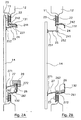
- FIGS. 2A and 2B show the device of FIG. 1 in section.
- the frame 11 is secured to the edge 21 of the body by a putty 22, which provides both the bonding and sealing.
- a putty 22 which provides both the bonding and sealing.
- other fastening means such as riveting, can be provided.
- This frame 11 also carries, on its outer face, a seal 23, which seals when the ice 14 is closed ( Figure 2A).
- This aspect is very advantageous because it allows sealing during the manufacture of the device. When mounting, simply glue the frame to the body, without worrying about the problem of sealing at the ice.
- the frame 11 is provided with an upper rail 131 and a lower rail 132, with which the connecting elements 151 and 152 cooperate.
- the upper connecting element 151 comprises a first member 24 and a second member 25, interconnected.
- An end 241 of the first member 24 is rotatably mounted on the guide rail 131. In the closed position, this member 24 is substantially horizontal (FIG. 2A). It is found vertical in the release position ( Figure 2B).
- the second member 25 has a first end 251 fixed, for example by gluing, to the crystal 14.
- the second end 252 is articulated on the second end 242 of the first member 24. This second member 25 remains substantially horizontal in both positions, of way to push the ice outward, in the release position ( Figure 2B).
- the lower connecting element 152 also similarly comprises two members 26 and 27 hinged together at their respective ends 262 and 272.
- the other end 261 of the member 26 is rotatably mounted on the sliding rail 132
- the other end 271 of the member 27 is secured to the crystal 14.
- the member 26 In the closed position, the member 26 is substantially horizontal. It goes practically vertically in the release position. The member 27 remains in turn substantially in the same plane slightly inclined relative to the horizontal.
- the locking of the mirror is provided for example by a cam 28 which bears on the outside face of the rail 132, and which holds the hinge 262, 272.
- FIG. 3 illustrates the ice of FIG. 1, provided with its connecting elements 151 and 152. These latter extend over a part (substantially one half) of the length of the ice, which allows a partial opening (see FIG. 1) of the bay. It is of course not possible to completely clear this opening ... We therefore choose a compromise between the maximum opening and the length of the connecting elements. This must be sufficient to ensure the solid retention of the ice, and good rigidity of the assembly, so that the sliding is easy and that the seal is guaranteed in the closed position.
- Figure 4 illustrates the corresponding frame, provided with rails 131 and 132, which may be made directly in the same material as the frame 14, or reported thereon. These rails preferably extend over the entire length of the frame, so as to maximize the length of contact with the connecting elements 151 and 152.
- FIG. 5 schematically illustrates a method of manufacturing and mounting a device as described above.
- the shutter device is manufactured.
- a frame substantially corresponding to the contour of the bay (51), which is equipped with guide rails.
- ice (52) is produced corresponding substantially to the surface of the bay, on which the connecting elements are reported.
- the window is secured (53) to the frame, after having placed on the frame the gasket 23.
- the device thus produced can then be delivered to a manufacturer, who has only to mount (54) on the body of a vehicle, using a suitable sealant.
Landscapes
- Engineering & Computer Science (AREA)
- Mechanical Engineering (AREA)
- Window Of Vehicle (AREA)
Claims (10)
- Verschlussvorrichtung einer Öffnung in der Karosserie (12) eines Fahrzeugs, die einen Rahmen (11) aufweist, der auf diese Karosserie aufgebracht werden soll, sowie eine gegenüber dem Rahmen (11) bewegliche Glasscheibe (14), die mit dem Rahmen (11) mit Hilfe von Verbindungselementen (151, 152, 24, 25, 26, 27) verbunden ist, welche die Bewegung der Glasscheibe (14) senkrecht zur Ebene der Öffnung zwischen den folgenden Positionen ermöglichen:- eine Position zum Verschließen der Öffnung, bei der die Glasscheibe (14) an dem Rahmen (11) anliegt, wobei sie in etwa in der Ebene der Karosserie liegt, und- eine Freigabeposition, wobei die Glasscheibe (14) zum Fahrzeugäußeren hin in einer Öffnungsebene verschoben ist,dadurch gekennzeichnet, dass die Verbindungselemente (151, 152, 24, 25, 26, 27) auch eine Gleitbewegung der Glasscheibe (14) über eine vorgegebene Länge entlang der Öffnungsebene ermöglichen, wobei die Glasscheibe (14) dauernd parallel zur Ebene der Öffnung verbleibt.
- Verschlussvorrichtung nach Anspruch 1,
dadurch gekennzeichnet, dass sie über Mittel zum Abdichten (23) zwischen dem Rahmen (11) und der Glasscheibe (14) verfügt, wenn diese sich in der Verschlussposition befindet. - Verschlussvorrichtung nach Anspruch 2,
dadurch gekennzeichnet, dass die Mittel zum Abdichten eine an dem Rahmen befestigte Dichtung (23) aufweisen. - Vorrichtung nach einem der Ansprüche 1 bis 3,
dadurch gekennzeichnet, dass der Rahmen (11) an der Karosserie mit Hilfe eines Befestigungs- und Dichtmaterials (22) befestigt ist. - Verschlussvorrichtung nach einem der Ansprüche 1 bis 4,
dadurch gekennzeichnet, dass jedes der Verbindungselemente (151, 152) mit einer an dem Rahmen angebrachten Führungsschiene (131, 132) zusammenwirkt. - Verschlussvorrichtung nach einem der Ansprüche 1 bis 5,
dadurch gekennzeichnet, dass die Verbindungsmittel (151, 152) jeweils mindestens zwei Gelenke (24, 25, 26, 27) umfassen, um sicherzustellen, dass die Glasscheibe ebenfalls parallel zu der von der Öffnung gebildeten Ebene verschoben ist, wenn sie sich in der Freigabeposition befindet. - Verschlussvorrichtung nach einem der Ansprüche 5 bis 6,
dadurch gekennzeichnet, dass jedes der Verbindungselemente folgendes umfasst:- ein erstes Gelenkorgan (24, 26), dessen eines Ende in der Schiene (131, 132) gleiten kann und zwischen zwei Extrempositionen im Verhältnis zur besagten Schiene geschwenkt werden kann, und- ein zweites Gelenkorgan (25, 27), von dem ein erstes Ende drehbar auf dem zweiten Ende des ersten Gelenkorgans angebracht ist und dessen zweites Ende an der Glasscheibe (14) befestigt ist. - Verschlussvorrichtung nach einem der Ansprüche 5 bis 7,
dadurch gekennzeichnet, dass sie ein oberes Gelenkelement (151, 24, 25) aufweist, das mit einer oberen Führungsschiene (131) zusammenwirkt, welche mit dem oberen Teil des Rahmens verbunden ist, und ein unteres Gelenkelement (152, 26, 27), das mit einer unteren Führungsschiene (132) zusammenwirkt, die mit dem unteren Teil des Rahmens verbunden ist. - Verschlussvorrichtung nach einem der Ansprüche 1 bis 8,
dadurch gekennzeichnet, dass sie über Verriegelungsmittel (28) der Glasscheibe in der Verschlussposition verfügt, die auf mindestens eines der Verbindungselemente (26, 27) wirken. - Fertigungs- und Montageverfahren einer Vorrichtung zum Abdecken einer Öffnung in einer Fahrzeugkarosserie,
dadurch gekennzeichnet, dass es die folgenden Schritte umfasst:- Fertigung eines Rahmens (11), der in etwa dem Umriss der Öffnung entspricht;- Fertigung einer Glasscheibe (14), die in etwa der Fläche der Öffnung entspricht;- Verbindung der Glasscheibe (14) mit dem Rahmen (11) mit Hilfe von Verbindungselementen (151, 152), die das Bewegen der Glasscheibe senkrecht zur Ebene der Öffnung zwischen den folgenden Positionen ermöglicht:- einer Verschlussposition der Öffnung, bei der die Glasscheibe an dem Rahmen anliegt, so dass sie in etwa in der Ebene der Karosserieöffnung liegt, und- einer Freigabeposition, bei der die Glasscheibe zum Äußeren des Fahrzeugs hin in einer Öffnungsebene verschoben ist,wobei die Verbindungselemente ebenfalls eine Gleitbewegung der Glasscheibe (14) über eine vorgegebene Länge entlang der Öffnungsebene zulassen, wobei die Glasscheibe (14) dauernd parallel zur Öffnungsebene verbleibt;- Anbindung des Rahmens (11) an die Karosserie (12).
Applications Claiming Priority (2)
| Application Number | Priority Date | Filing Date | Title |
|---|---|---|---|
| FR9807264 | 1998-06-05 | ||
| FR9807264A FR2779389B1 (fr) | 1998-06-05 | 1998-06-05 | Dispositif d'obturation d'une baie menagee dans la carrosserie d'un vehicule, a coulissement exterieur, et procede de fabrication et de montage correspondant |
Publications (2)
| Publication Number | Publication Date |
|---|---|
| EP0962346A1 EP0962346A1 (de) | 1999-12-08 |
| EP0962346B1 true EP0962346B1 (de) | 2006-09-06 |
Family
ID=9527201
Family Applications (1)
| Application Number | Title | Priority Date | Filing Date |
|---|---|---|---|
| EP19990460038 Expired - Lifetime EP0962346B1 (de) | 1998-06-05 | 1999-06-04 | Abschlussvorrichtung für eine Öffnung einer Fahrzeugkarosserie, mit Aussengleitung und Herstellungsverfahren und entsprechende Montagevorrichtung |
Country Status (3)
| Country | Link |
|---|---|
| EP (1) | EP0962346B1 (de) |
| DE (1) | DE69933086T2 (de) |
| FR (1) | FR2779389B1 (de) |
Families Citing this family (5)
| Publication number | Priority date | Publication date | Assignee | Title |
|---|---|---|---|---|
| FR2792881B1 (fr) * | 1999-04-27 | 2001-07-20 | Wagon Automotive Snc | Dispositif d'obturation d'une baie menagee dans la carrosserie d'un vehicule, a element(s) d'etancheite et/ou de rigidification, et procede de fabrication correspondant |
| FR2833211A1 (fr) * | 2001-12-10 | 2003-06-13 | Wagon Automotive Snc | Dispositif motorise d'obturation d'une baie menagee dans un vehicule automobile, et vehicule correspondant |
| DE10309185B8 (de) * | 2003-03-03 | 2010-08-05 | Volkswagen Ag | Schiebefenster für ein Fahrzeug |
| FR2885381A1 (fr) * | 2005-05-09 | 2006-11-10 | Cooper Standard Automotive Fra | Fenetre a panneau coulissant |
| DE102018128307B4 (de) * | 2018-11-13 | 2023-03-30 | Bayerische Motoren Werke Aktiengesellschaft | Seitenstruktur für einen Personenkraftwagen, mit einer absenkbaren Seitenscheibe, sowie Personenkraftwagen |
Family Cites Families (3)
| Publication number | Priority date | Publication date | Assignee | Title |
|---|---|---|---|---|
| DE3343366A1 (de) * | 1983-11-30 | 1985-06-05 | Schaumburg-Lippische Baubeschlag-Fabrik W. Hautau GmbH, 3061 Helpsen | Beschlag fuer den schiebefluegel von fenstern oder tueren |
| JPH065219Y2 (ja) * | 1987-02-06 | 1994-02-09 | アイシン精機株式会社 | 車両用サイドウインド |
| DE4416827A1 (de) * | 1994-05-16 | 1995-11-23 | Schade Kg | Fahrzeugschiebefenster |
-
1998
- 1998-06-05 FR FR9807264A patent/FR2779389B1/fr not_active Expired - Fee Related
-
1999
- 1999-06-04 EP EP19990460038 patent/EP0962346B1/de not_active Expired - Lifetime
- 1999-06-04 DE DE1999633086 patent/DE69933086T2/de not_active Expired - Lifetime
Also Published As
| Publication number | Publication date |
|---|---|
| DE69933086T2 (de) | 2007-04-05 |
| DE69933086D1 (de) | 2006-10-19 |
| FR2779389A1 (fr) | 1999-12-10 |
| FR2779389B1 (fr) | 2000-09-01 |
| EP0962346A1 (de) | 1999-12-08 |
Similar Documents
| Publication | Publication Date | Title |
|---|---|---|
| EP3356170A1 (de) | Bündig verglaste vorrichtung für fahrzeugtür und zugehörige tür, kraftfahrzeug, herstellungsverfahren und abdichtvorrichtung | |
| EP0787240A1 (de) | Einrastbare verglasung und montage der verglasung in dem rahmen eines öffnung | |
| EP1022172B1 (de) | Herstellungsverfahren einer Fahrzeugtür, und korrespondierende Tür | |
| EP3647093A1 (de) | Verglaste vorrichtung eines fahrzeugs mit demontierbarem gleitschuh, entsprechende tür, entsprechendes fahrzeug und montageverfahren | |
| EP4110634B1 (de) | Fahrzeug mit mindestens einem zweiteiligen fenster mit einem kippbaren teil und einer zwischen den beiden teilen angeordneten dichtung | |
| EP0962346A1 (de) | Abschlussvorrichtung für eine Öffnung einer Fahrzeugkarosserie, mit Aussengleitung und Herstellungsverfahren und entsprechende Montagevorrichtung | |
| EP1140535A1 (de) | Sicherheitsvorrichtung mit glasöffnung mit beweglichem verschluss | |
| EP0956987B1 (de) | Abschlussvorrichtung für Karosserieöffnung und Verfahren zum Herstellen und Montieren | |
| FR2861118A1 (fr) | Ensemble de fermeture de la baie d'une carrosserie | |
| EP1048501B1 (de) | Abschlussvorrichtung für Öffnung in einer Fahrzeugkarosserie mit Wasserdurchfuhr | |
| EP3898303A1 (de) | Glasscheibe mit einer verkapselten profilierten verbindung mit einem befestigten teil, das mithilfe eines hakens gesichert ist | |
| FR2657148A1 (fr) | Bloc optique a reflecteur articule pour vehicule automobile. | |
| EP1048500B1 (de) | Abschlussvorrichtung für eine Karosserieöffnung, mit Dichtungs- und/oder Versteifungselement, und korrespondierendes Herstellungsverfahren | |
| FR2782298A1 (fr) | Dispositif d'obturation d'une baie de vehicule, joint d'etancheite et procede de montage correspondants | |
| FR2829971A1 (fr) | Dispositif d'obturation d'une baie menagee dans un vehicule automobile, a rails non paralleles, et vehicule correspondant | |
| FR2985224A1 (fr) | Pavillon vitre de vehicule, equipe d'un panneau mobile coulissant, et vehicule correspondant | |
| EP1074409B2 (de) | In ein Fenster eingesetzte innengedichtete Fensterscheibe für ein Fahrzeug | |
| EP1595727B1 (de) | Abschlussvorrichtung für eine Karosserieöffnung eines Fahrzeuges, Herstellungsverfahren und Fahrzeug dazu. | |
| EP1741586B1 (de) | Abschlussvorrichtung für eine Fahrzeugöffnung mit innerer Dichtung, Herstellungsverfahren und entsprechendes Fahrzeug | |
| FR2905899A1 (fr) | Ouvrant arriere de vehicule automobile | |
| FR2937911A1 (fr) | Dispositif d'obturation d'une baie menagee dans un vehicule automobile, a lame ressort de liaison, et vehicule correspondant | |
| FR2847520A1 (fr) | Portiere de vehicule automobile a panneau vitre coulissant, et ensemble superieur de portiere, procede de fabrication et vehicule correspondants | |
| FR2885381A1 (fr) | Fenetre a panneau coulissant | |
| FR2770574A1 (fr) | Dispositif d'etancheite pour chassis a frappe a ouvrant a deux vantaux | |
| FR2778607A1 (fr) | Dispositif d'obturation d'une baie menagee dans la carrosserie d'un vehicule, et procede de fabrication et de montage correspondant |
Legal Events
| Date | Code | Title | Description |
|---|---|---|---|
| PUAI | Public reference made under article 153(3) epc to a published international application that has entered the european phase |
Free format text: ORIGINAL CODE: 0009012 |
|
| AK | Designated contracting states |
Kind code of ref document: A1 Designated state(s): DE ES GB IT |
|
| AX | Request for extension of the european patent |
Free format text: AL;LT;LV;MK;RO;SI |
|
| 17P | Request for examination filed |
Effective date: 20000215 |
|
| D17P | Request for examination filed (deleted) | ||
| R17P | Request for examination filed (corrected) |
Effective date: 20000229 |
|
| AKX | Designation fees paid |
Free format text: DE ES GB IT |
|
| RAP1 | Party data changed (applicant data changed or rights of an application transferred) |
Owner name: WAGON SAS |
|
| GRAP | Despatch of communication of intention to grant a patent |
Free format text: ORIGINAL CODE: EPIDOSNIGR1 |
|
| GRAS | Grant fee paid |
Free format text: ORIGINAL CODE: EPIDOSNIGR3 |
|
| GRAA | (expected) grant |
Free format text: ORIGINAL CODE: 0009210 |
|
| AK | Designated contracting states |
Kind code of ref document: B1 Designated state(s): DE ES GB IT |
|
| PG25 | Lapsed in a contracting state [announced via postgrant information from national office to epo] |
Ref country code: IT Free format text: LAPSE BECAUSE OF FAILURE TO SUBMIT A TRANSLATION OF THE DESCRIPTION OR TO PAY THE FEE WITHIN THE PRESCRIBED TIME-LIMIT;WARNING: LAPSES OF ITALIAN PATENTS WITH EFFECTIVE DATE BEFORE 2007 MAY HAVE OCCURRED AT ANY TIME BEFORE 2007. THE CORRECT EFFECTIVE DATE MAY BE DIFFERENT FROM THE ONE RECORDED. Effective date: 20060906 Ref country code: GB Free format text: LAPSE BECAUSE OF FAILURE TO SUBMIT A TRANSLATION OF THE DESCRIPTION OR TO PAY THE FEE WITHIN THE PRESCRIBED TIME-LIMIT Effective date: 20060906 |
|
| REG | Reference to a national code |
Ref country code: GB Ref legal event code: FG4D Free format text: NOT ENGLISH |
|
| REF | Corresponds to: |
Ref document number: 69933086 Country of ref document: DE Date of ref document: 20061019 Kind code of ref document: P |
|
| PG25 | Lapsed in a contracting state [announced via postgrant information from national office to epo] |
Ref country code: ES Free format text: LAPSE BECAUSE OF FAILURE TO SUBMIT A TRANSLATION OF THE DESCRIPTION OR TO PAY THE FEE WITHIN THE PRESCRIBED TIME-LIMIT Effective date: 20061217 |
|
| GBV | Gb: ep patent (uk) treated as always having been void in accordance with gb section 77(7)/1977 [no translation filed] |
Effective date: 20060906 |
|
| PLBE | No opposition filed within time limit |
Free format text: ORIGINAL CODE: 0009261 |
|
| STAA | Information on the status of an ep patent application or granted ep patent |
Free format text: STATUS: NO OPPOSITION FILED WITHIN TIME LIMIT |
|
| 26N | No opposition filed |
Effective date: 20070607 |
|
| PGFP | Annual fee paid to national office [announced via postgrant information from national office to epo] |
Ref country code: DE Payment date: 20150622 Year of fee payment: 17 |
|
| REG | Reference to a national code |
Ref country code: DE Ref legal event code: R119 Ref document number: 69933086 Country of ref document: DE |
|
| PG25 | Lapsed in a contracting state [announced via postgrant information from national office to epo] |
Ref country code: DE Free format text: LAPSE BECAUSE OF NON-PAYMENT OF DUE FEES Effective date: 20170103 |