EP0962370A2 - Méthode de contrÔle du comportement du véhicule dans un parcours en courbe et système de freinage approprié à la dite méthode - Google Patents
Méthode de contrÔle du comportement du véhicule dans un parcours en courbe et système de freinage approprié à la dite méthode Download PDFInfo
- Publication number
- EP0962370A2 EP0962370A2 EP99201510A EP99201510A EP0962370A2 EP 0962370 A2 EP0962370 A2 EP 0962370A2 EP 99201510 A EP99201510 A EP 99201510A EP 99201510 A EP99201510 A EP 99201510A EP 0962370 A2 EP0962370 A2 EP 0962370A2
- Authority
- EP
- European Patent Office
- Prior art keywords
- brake pressure
- value
- function
- vehicle
- diag
- Prior art date
- Legal status (The legal status is an assumption and is not a legal conclusion. Google has not performed a legal analysis and makes no representation as to the accuracy of the status listed.)
- Withdrawn
Links
- 238000000034 method Methods 0.000 title abstract description 13
- 230000006870 function Effects 0.000 description 24
- 239000012530 fluid Substances 0.000 description 13
- 230000001965 increasing effect Effects 0.000 description 13
- 230000006399 behavior Effects 0.000 description 9
- 238000004364 calculation method Methods 0.000 description 2
- 230000002708 enhancing effect Effects 0.000 description 2
- 230000037361 pathway Effects 0.000 description 2
- 238000007796 conventional method Methods 0.000 description 1
- 238000001514 detection method Methods 0.000 description 1
- 238000010586 diagram Methods 0.000 description 1
- 230000000694 effects Effects 0.000 description 1
- 238000010801 machine learning Methods 0.000 description 1
- 238000005259 measurement Methods 0.000 description 1
- 238000005192 partition Methods 0.000 description 1
- 238000009877 rendering Methods 0.000 description 1
Images


Classifications
-
- B—PERFORMING OPERATIONS; TRANSPORTING
- B60—VEHICLES IN GENERAL
- B60T—VEHICLE BRAKE CONTROL SYSTEMS OR PARTS THEREOF; BRAKE CONTROL SYSTEMS OR PARTS THEREOF, IN GENERAL; ARRANGEMENT OF BRAKING ELEMENTS ON VEHICLES IN GENERAL; PORTABLE DEVICES FOR PREVENTING UNWANTED MOVEMENT OF VEHICLES; VEHICLE MODIFICATIONS TO FACILITATE COOLING OF BRAKES
- B60T8/00—Arrangements for adjusting wheel-braking force to meet varying vehicular or ground-surface conditions, e.g. limiting or varying distribution of braking force
- B60T8/17—Using electrical or electronic regulation means to control braking
- B60T8/1755—Brake regulation specially adapted to control the stability of the vehicle, e.g. taking into account yaw rate or transverse acceleration in a curve
-
- B—PERFORMING OPERATIONS; TRANSPORTING
- B60—VEHICLES IN GENERAL
- B60T—VEHICLE BRAKE CONTROL SYSTEMS OR PARTS THEREOF; BRAKE CONTROL SYSTEMS OR PARTS THEREOF, IN GENERAL; ARRANGEMENT OF BRAKING ELEMENTS ON VEHICLES IN GENERAL; PORTABLE DEVICES FOR PREVENTING UNWANTED MOVEMENT OF VEHICLES; VEHICLE MODIFICATIONS TO FACILITATE COOLING OF BRAKES
- B60T2201/00—Particular use of vehicle brake systems; Special systems using also the brakes; Special software modules within the brake system controller
- B60T2201/16—Curve braking control, e.g. turn control within ABS control algorithm
Definitions
- This invention relates to a method for controlling the behaviour of an automotive vehicle during cornering and to a braking system for implementing such a method.
- the present invention concerns a method wherein, using the wheel speed of the vehicle, the hydraulic brake pressure available to the wheel brakes is modified according to intended road-holding qualities.
- ABS Anti-Lock Braking System
- DRP Dynamic Rear Proportioning System
- This type of braking system is quite efficient while the vehicle is moving in a substantial linear pathway, but is prone to be less accurate during cornering, due to the fact that the regulation of the braking balance is carried out using the front and rear wheel speed differential value which is liable to not be high enough, during cornering, to generate a consistent data.
- Another object of the invention is to provide a braking system carrying out the above method.
- the present invention provide a method for controlling the behaviour of an automotive vehicle during cornering consisting in measuring the rotational wheel speed of the front and rear wheels of the vehicle, establishing the wheel speed difference between the front and rear wheels and modifying the brake pressure applied to the rear wheel brakes of the vehicle according to a vehicle behaviour to be obtained, comprising the steps of:
- the invention provides a braking system intended to implement the above method, said system including Dynamic Rear Proportioning means and further comprises:
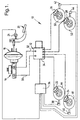
- the vehicle braking system illustrated on figure 1, denoted by the general reference numeral 10, is mainly constituted by an Anti-lock Braking system (ABS) 12, a Dynamic Rear Proportioning system (DRP) including DRP processing means and an associated memory (not shown), and an hydraulic system associated with conventional brake means.
- ABS Anti-lock Braking system
- DRP Dynamic Rear Proportioning system
- the hydraulic system comprises a conventional master cylinder 16 associated with a known per-se booster 18.
- the master cylinder 16 may be operated by the vehicle driver through a brake pedal 20 associated with a brake switch sensor 21 for applying fluid pressure, with power assist, to front wheel brakes 22 and 24 and rear wheel brakes 26 and 28.
- Fluid pressure is applied to the front wheel brakes 22,24 through a fluid line 30 and fluid pressure is applied to rear wheel brakes 26,28 via a fluid line 32.
- ABS modulator 34 of the ABS system 12 is included in the fluid lines 30 and 32 and controls, under control of an ABS controller 36, the fluid pressure applied to the front and rear brakes 22-28 in order to reduce the pressure to the brakes upon detection of wheel instability, for example when wheel deceleration exceeds a predetermined limit.
- a set of wheel speed sensors 38, 40, 42 and 44, facing each wheel 46, 48, 50 and 52 respectively, provides the ABS controller 36 with data concerning the rotational speed of the vehicle wheels.
- the system illustrated in figure 1 is completed by power supply means (not shown) associated with a switch for turning the ABS and DRP systems on and off.
- DRP system can be considered as a sub-system of the ABS system.
- Information shared by ABS and DRP as well as information specifically calculated for the DRP function is used for control of rear brakes 26,28.
- the DRP processing means (which is preferably incorporated in the controller 36) controls a variation of the fluid pressure partition between the rear and front brakes 26,28,22,24 according to the intended road-holding qualities, by means of a DRP algorithm stored in the memory of the DRP system and implemented in the DRP processing means.
- the DRP processing means first detects at step 54 that the vehicle is actually cornering, using a conventional technique, based for example on wheel speed measurements.
- the DRP processing means detects the corner direction, namely as to whether it is a left or a right corner.
- DRP processing means calculates the absolute value of the difference between the left front wheel speed and the right rear wheel speed (step 58).
- DRP processing means calculates the absolute value of the difference between the right front wheel speed and the left rear wheel speed (step 60).
- DIAG variable This calculated variable will be called hereinafter DIAG variable.
- the DRP processing means elaborates a function which will be called below ADJ_DIAG function and which will be used to determine the brake pressure variations to be applied to the rear brakes 26,28.
- DIAG variable is adjusted according to the intended road-holding qualities.
- DIAG variable is multiplied by a predetermined multiplier factor stored in the memory of the system and obtained by previous machine learning, said factor constituting a gain intended to compensate for the calculated variable value according to the vehicle behaviour to be obtained and the vehicle features, for example the length thereof.
- the multiplier factor can modify oversteering or understeering behaviour of the vehicle.
- step 64 the value of the function ADJ_DIAG obtained at the end of step 62 is compared with a threshold value, and if said function value is above this threshold value, the value of this latter is allocated to the value of ADJ_DIAG function (step 66).
- the above computed function ADJ_DIAG is then input into a low-pass filter, for example a first order filter, in order to eliminate noise (step 68).
- a low-pass filter for example a first order filter
- the filtered function value is then compared with a brake release threshold (step 70). If said function value is above this second threshold value, it is decided at step 72 that the brake fluid pressure applied to the left and right rear brakes 26 and 28 is to be released.
- the value of the filtered function ADJ_DIAG is compared with a brake holding threshold value above which the pressure applied to the rear brakes is held constant.
- the pressure applied to the rear brakes 26,28 is kept constant regardless of the pressure applied under the control of brake pedal 20 to the front brakes 22,24 (step 76), and if it is not the case, i.e. if the filtered function value is less than the brake holding threshold value, the pressure applied to the rear brakes is kept unmodified, namely equal to the pressure in the fluid line 32 (step 78).
- the DRP processing means is also able to increase the brake pressure applied to the rear brakes 26,28 when the vehicle is stable enough in order to enhance the braking efficiency, as explained below with reference to figure 3.
- the routine implemented for that purpose begins with a first step 80 during which the DRP system checks whether the vehicle is actually cornering.
- the adjusted function value ADJ_DIAG obtained at the end of above mentioned steps 64 and 66 is compared with a fourth threshold value which corresponds to a minimal stability condition above which the rear brake pressure increasing is allowed.
- step 84 it is checked whether the vehicle is stable enough for increasing the rear brake pressure, by comparing the value of the function ADJ_DIAG with a fifth threshold value which corresponds to a maximal stability condition above which the brake pressure increasing is not allowed.
- the adjusted value lies within the range delimited by the above fourth and fifth threshold values, it is then checked, during the next steps 86 and 88, whether the vehicle speed lies within a predetermined range, for example above 20 km/h and below 120 km/h, in order to avoid any pressure increasing if the vehicle speed is less than this lower speed value (step 86), which would render the rear brake pressure increasing of no interest and above the upper speed value (step 88), which may render the brake pressure increasing excessive.
- a predetermined range for example above 20 km/h and below 120 km/h
- step 90 if the vehicle speed lies within said predetermined range, the brake pressure applied to the rear brakes 26,28 which has been previously held or released, is increased in order to enhance the braking efficiency.
- the brake pressure is increased in the form of pressure steps in order to be in a position to check, after each step, the vehicle stability.
- step 92 the number of steps is compared with a step number threshold value (step 92).
- the rear brake pressure is then continuously increased up to a value equal to the pressure value in the fluid line 32 (step 94).
- routines described in reference to figures 2 and 3 permit, by means of the calculation of the absolute value of the difference between the inner front wheel speed and the outer rear wheel speed, which provide some information about the corner radius and the vehicle speed, to hold at a constant value, or release, or increase, or let the rear brake pressure follow the pressure applied by the master cylinder 16 of a vehicle while cornering, in order, on the one hand, to enhance the vehicle stability, and, on the other hand, if the vehicle is stable enough, to enhance the braking efficiency by reducing the braking distance.
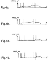
- Figures 4a-4d depict the brake pressure, PRES_LF, PRES_RF, PRES_LR and PRES_RR as a function of time, applied to the left and right front and rear brakes, respectively, of a vehicle during cornering, at about 120 km/h.
- Figure 4e depicts the variations of a signal CORNER during an aggressive manoeuvre delivered at the end of the above-mentioned step 56 during which the cornering is detected. This signal is high as long as the vehicle is cornering and is low when the vehicle is moving along a linear pathway.
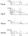
- Figures 4f and 4g show the variation, as a function of time, of the filtered function ADJ_DIAG and of the speed vehicle SPEED, respectively.
- figure 4h illustrates the signal DRP_MODE corresponding to the running mode of the DRP processing means.
- the signal DRP_MODE is high when, during step 70, it has been detected that the value of ADJ_DIAG is above the corresponding release threshold value and that the rear brake pressure is to be released.
- This signal is low when it has been decided, at step 92, that the rear brake pressure is to be reapplied up to a value equal to that of the pressure in the fluid line 32.
- this signal is set at a intermediate value when, at step 74, it has been decided that the brake pressure applied to the rear brakes 26,28 is to be kept substantially constant.
- the vehicle driver actuates the brake pedal 20, which tends to increase the brake pressure applied to the front and rear brakes 22-28.
- figure 4f shows that as soon as the value of ADJ_DIAG is above the above-mentioned brake release threshold value T2 (time t2), the DRP system is set in a release mode in order to release the right and left rear brake pressure, rendering the signals shown on figures 4c and 4d substantially equal to 0 until ADJ_DIAG drops below this second threshold value T2.
- ADJ_DIAG drops below the brake holding threshold value (time t3), increasing of the rear brake pressure is allowed.
- the brake pressure is first increased in the form of steps and, when the number of steps is above a predetermined value, the pressure is reapplied in a substantially continuous way (time t5) in order to shorten the braking distance.
Landscapes
- Engineering & Computer Science (AREA)
- Transportation (AREA)
- Mechanical Engineering (AREA)
- Regulating Braking Force (AREA)
- Hydraulic Control Valves For Brake Systems (AREA)
Applications Claiming Priority (2)
| Application Number | Priority Date | Filing Date | Title |
|---|---|---|---|
| GB9811585 | 1998-06-01 | ||
| GBGB9811585.0A GB9811585D0 (en) | 1998-06-01 | 1998-06-01 | Method for controlling vehicle behaviour during cornering and a braking system for implementation thereof |
Publications (2)
| Publication Number | Publication Date |
|---|---|
| EP0962370A2 true EP0962370A2 (fr) | 1999-12-08 |
| EP0962370A3 EP0962370A3 (fr) | 2000-12-13 |
Family
ID=10832917
Family Applications (1)
| Application Number | Title | Priority Date | Filing Date |
|---|---|---|---|
| EP99201510A Withdrawn EP0962370A3 (fr) | 1998-06-01 | 1999-05-14 | Méthode de contrôle du comportement du véhicule dans un parcours en courbe et système de freinage approprié à la dite méthode |
Country Status (3)
| Country | Link |
|---|---|
| US (1) | US6272419B1 (fr) |
| EP (1) | EP0962370A3 (fr) |
| GB (1) | GB9811585D0 (fr) |
Cited By (5)
| Publication number | Priority date | Publication date | Assignee | Title |
|---|---|---|---|---|
| EP1136334A1 (fr) * | 2000-03-20 | 2001-09-26 | Robert Bosch GmbH | Amélioration du guidage et de la stabilité d'un véhicule lors de la négociation d'un virage avec freinage |
| FR2810952A1 (fr) * | 2000-06-30 | 2002-01-04 | Bosch Gmbh Robert | Procede de detection d'un changement de file et dispositif pour la mise en oeuvre dudit procede |
| FR2818219A1 (fr) | 2000-12-18 | 2002-06-21 | Delphi Tech Inc | Procede de commande ameliore pour le freinage d'un vehicule automobile en virage et systeme pour sa mise en oeuvre |
| FR2841200A1 (fr) * | 2002-06-21 | 2003-12-26 | Delphi Tech Inc | Procede et dispositif pour le freinage en courbe d'un vehicule atomobile |
| EP3747715A1 (fr) * | 2019-06-04 | 2020-12-09 | Mazda Motor Corporation | Système de commande d'attitude d'un véhicule |
Families Citing this family (4)
| Publication number | Priority date | Publication date | Assignee | Title |
|---|---|---|---|---|
| US20050038589A1 (en) * | 2003-08-14 | 2005-02-17 | Deepak Shukla | Method for estimating a friction coefficient |
| US20050038588A1 (en) * | 2003-08-14 | 2005-02-17 | Deepak Shukla | Vehicle driving force control method |
| US6964460B2 (en) * | 2003-12-03 | 2005-11-15 | Delphi Technologies, Inc. | Brake controller and method for controlling a brake system |
| US7159954B2 (en) * | 2003-12-29 | 2007-01-09 | Bendix Commercial Vehicle Systems, Llc | ABS control system for off-road driving conditions |
Family Cites Families (10)
| Publication number | Priority date | Publication date | Assignee | Title |
|---|---|---|---|---|
| DE3421732A1 (de) | 1984-06-12 | 1985-12-12 | Robert Bosch Gmbh, 7000 Stuttgart | Antiblockierregelsystem |
| DE3602432A1 (de) * | 1986-01-28 | 1987-07-30 | Bosch Gmbh Robert | Antiblockierregelsystem |
| DE3739558A1 (de) * | 1987-11-21 | 1989-06-01 | Bosch Gmbh Robert | Verfahren zur erzeugung eines eine kurvenfahrt anzeigenden signals |
| DE4112388A1 (de) * | 1991-04-16 | 1992-10-22 | Bosch Gmbh Robert | Bremsdruckregelanlage fuer ein fahrzeug |
| DE4241844A1 (de) * | 1992-12-11 | 1994-06-16 | Bosch Gmbh Robert | Bremssystem |
| DE19510746A1 (de) * | 1995-03-24 | 1996-09-26 | Bosch Gmbh Robert | Verfahren und Vorrichtung zur Steuerung der Bremsanlage eines Fahrzeugs |
| DE19522632A1 (de) * | 1995-06-22 | 1997-01-02 | Teves Gmbh Alfred | Verfahren zur Verbesserung des Regelverhaltens eines Blockierschutzregelungssystems |
| US5646849A (en) * | 1995-08-09 | 1997-07-08 | General Motors Corporation | Method for proportionally controlling the brakes of a vehicle based on front and rear wheel speeds |
| US5632535A (en) * | 1995-08-28 | 1997-05-27 | Kelsey-Hayes Company | Dynamic rear proportioning brake system |
| DE19620584B4 (de) * | 1996-05-22 | 2005-11-03 | Continental Teves Ag & Co. Ohg | Verfahren zur Emittlung eines Eintrittkriteriums in die elektronischen Bremskraftverteilung |
-
1998
- 1998-06-01 GB GBGB9811585.0A patent/GB9811585D0/en not_active Ceased
-
1999
- 1999-05-14 EP EP99201510A patent/EP0962370A3/fr not_active Withdrawn
- 1999-05-24 US US09/317,345 patent/US6272419B1/en not_active Expired - Fee Related
Non-Patent Citations (1)
| Title |
|---|
| None |
Cited By (6)
| Publication number | Priority date | Publication date | Assignee | Title |
|---|---|---|---|---|
| EP1136334A1 (fr) * | 2000-03-20 | 2001-09-26 | Robert Bosch GmbH | Amélioration du guidage et de la stabilité d'un véhicule lors de la négociation d'un virage avec freinage |
| US6523914B2 (en) | 2000-03-20 | 2003-02-25 | Robert Bosch Gmbh | Vehicle steerability and driving stability while braking in a curve |
| FR2810952A1 (fr) * | 2000-06-30 | 2002-01-04 | Bosch Gmbh Robert | Procede de detection d'un changement de file et dispositif pour la mise en oeuvre dudit procede |
| FR2818219A1 (fr) | 2000-12-18 | 2002-06-21 | Delphi Tech Inc | Procede de commande ameliore pour le freinage d'un vehicule automobile en virage et systeme pour sa mise en oeuvre |
| FR2841200A1 (fr) * | 2002-06-21 | 2003-12-26 | Delphi Tech Inc | Procede et dispositif pour le freinage en courbe d'un vehicule atomobile |
| EP3747715A1 (fr) * | 2019-06-04 | 2020-12-09 | Mazda Motor Corporation | Système de commande d'attitude d'un véhicule |
Also Published As
| Publication number | Publication date |
|---|---|
| US6272419B1 (en) | 2001-08-07 |
| EP0962370A3 (fr) | 2000-12-13 |
| GB9811585D0 (en) | 1998-07-29 |
Similar Documents
| Publication | Publication Date | Title |
|---|---|---|
| US4824183A (en) | Dual-circuit hydraulic anti-lock braking system | |
| US5624164A (en) | Braking force distribution control system | |
| EP0342789B1 (fr) | Méthode pour estimer la vitesse et l'accélération de référence pour commande d'entraînement et de freinage à antipatinage | |
| US7125086B2 (en) | Vehicle dynamics control system | |
| GB2157381A (en) | Slip-controlled brake system for road vehicles | |
| US7066559B2 (en) | Brake pressure estimating apparatus and method | |
| EP0767093B1 (fr) | Dispositif de contrôle de stabilité pour véhicules | |
| US5855419A (en) | Process for controlling a distribution of braking force in a vehicle | |
| US6280003B1 (en) | Method of braking force distribution control for a vehicle hydraulic device | |
| US5380072A (en) | Trailer stability system and method | |
| US6238018B1 (en) | Process for controlling braking-force distribution in vehicle | |
| US6272419B1 (en) | Method for controlling vehicle behavior during cornering and a braking system for implementation thereof | |
| US5646848A (en) | Method for proportionally controlling the brakes of a vehicle based on tire deformation | |
| US7185957B2 (en) | Braking force distribution control apparatus and method | |
| US6246946B1 (en) | Automotive brake control system with skid control unit | |
| CA1252181A (fr) | Systeme de controle antiderapage reagissant a l'etat de surface de la chaussee | |
| EP0770528B1 (fr) | Dispositif de commande de stabilité de véhicule préparé pour un freinage manuel arrivant suite à la fin de la commande de stabilité | |
| US6431663B1 (en) | Process and device to improve the regulating action of an anti-lock braking system | |
| US6974195B2 (en) | Method for increasing the maneuverability or driving stability of a vehicle during cornering | |
| JP3248272B2 (ja) | 制動力配分制御装置 | |
| KR100221574B1 (ko) | 차량의 제동력 배분 제어방법 | |
| JP3205684B2 (ja) | 車両のブレーキ力配分制御方法 | |
| US6375280B1 (en) | Method and device for adjusting the braking action in a motor vehicle | |
| JP3456012B2 (ja) | アンチスキッド制御装置 | |
| JP3146718B2 (ja) | 制動力制御装置 |
Legal Events
| Date | Code | Title | Description |
|---|---|---|---|
| PUAI | Public reference made under article 153(3) epc to a published international application that has entered the european phase |
Free format text: ORIGINAL CODE: 0009012 |
|
| AK | Designated contracting states |
Kind code of ref document: A2 Designated state(s): DE FR GB IT |
|
| AX | Request for extension of the european patent |
Free format text: AL;LT;LV;MK;RO;SI |
|
| PUAL | Search report despatched |
Free format text: ORIGINAL CODE: 0009013 |
|
| AK | Designated contracting states |
Kind code of ref document: A3 Designated state(s): AT BE CH CY DE DK ES FI FR GB GR IE IT LI LU MC NL PT SE |
|
| AX | Request for extension of the european patent |
Free format text: AL;LT;LV;MK;RO;SI |
|
| 17P | Request for examination filed |
Effective date: 20010613 |
|
| AKX | Designation fees paid |
Free format text: DE FR GB IT |
|
| 17Q | First examination report despatched |
Effective date: 20030521 |
|
| STAA | Information on the status of an ep patent application or granted ep patent |
Free format text: STATUS: THE APPLICATION IS DEEMED TO BE WITHDRAWN |
|
| 18D | Application deemed to be withdrawn |
Effective date: 20041201 |