EP0962382A1 - Fixing device for the mudguard of a bicycle - Google Patents
Fixing device for the mudguard of a bicycle Download PDFInfo
- Publication number
- EP0962382A1 EP0962382A1 EP99110866A EP99110866A EP0962382A1 EP 0962382 A1 EP0962382 A1 EP 0962382A1 EP 99110866 A EP99110866 A EP 99110866A EP 99110866 A EP99110866 A EP 99110866A EP 0962382 A1 EP0962382 A1 EP 0962382A1
- Authority
- EP
- European Patent Office
- Prior art keywords
- plug
- connection
- bracket
- spherical
- mudguard
- Prior art date
- Legal status (The legal status is an assumption and is not a legal conclusion. Google has not performed a legal analysis and makes no representation as to the accuracy of the status listed.)
- Granted
Links
- 238000003780 insertion Methods 0.000 claims description 6
- 230000037431 insertion Effects 0.000 claims description 6
- 230000008878 coupling Effects 0.000 abstract 3
- 238000010168 coupling process Methods 0.000 abstract 3
- 238000005859 coupling reaction Methods 0.000 abstract 3
- 238000000465 moulding Methods 0.000 description 2
- 230000001154 acute effect Effects 0.000 description 1
- 230000015572 biosynthetic process Effects 0.000 description 1
- 238000011161 development Methods 0.000 description 1
- 230000018109 developmental process Effects 0.000 description 1
- 230000000694 effects Effects 0.000 description 1
- 230000002093 peripheral effect Effects 0.000 description 1
- 230000001012 protector Effects 0.000 description 1
- 230000001960 triggered effect Effects 0.000 description 1
Images

Classifications
-
- B—PERFORMING OPERATIONS; TRANSPORTING
- B62—LAND VEHICLES FOR TRAVELLING OTHERWISE THAN ON RAILS
- B62J—CYCLE SADDLES OR SEATS; AUXILIARY DEVICES OR ACCESSORIES SPECIALLY ADAPTED TO CYCLES AND NOT OTHERWISE PROVIDED FOR, e.g. ARTICLE CARRIERS OR CYCLE PROTECTORS
- B62J15/00—Mud-guards for wheels
- B62J15/02—Fastening means; Stays
Definitions
- the present invention relates to a device for Attachment of struts to hold a mudguard on Frame of a bicycle comprising at least a first part, on the at least one section of at least one strut Bracket of the mudguard can be attached or is attached, as well as further comprising at least one second part, which is attachable to the bicycle frame, wherein the first and the second part via a detachable connection are interconnected, which is designed such that it then automatically detaches itself when one of the parts pulling force a predetermined limit exceeds.
- a device for fastening struts to the bracket a mudguard of the type mentioned is from the EP 0803429 (A2) is known.
- A2 is known.
- the object of the present invention is therefore a device for fastening struts to the bracket a mudguard on the frame of a bicycle at the entrance to create the type mentioned, in which a defined Release force as independent of the direction from which the forces are introduced is given.
- an object of the invention provides the solution to this problem Device for fastening struts to hold a Mudguards on the frame of a bicycle of the aforementioned Genus with the characterizing features of the claim 1.
- the connection between the first and second part formed such that interconnected first and second part about at least one axis are at least partially pivotable against each other, wherein this axis to the connecting line between the first and second part is inclined, preferably perpendicular to this is. Due to the at least partial pivotability of the two interconnected parts against each other that will Triggers the detachable connection even with oblique Force application at least approximately at the same predetermined Release force take place.
- the first part of a connector the one Includes recording
- the second part is an insertion part, that with a section that is preferably used as an extension is formed, can be inserted into the receptacle, with Insert this section into the holder preferably designed as a detachable detachable connection Connection formed between the connecting part and the plug-in part becomes.
- connection part can be accommodated be spherical or partially spherical, the Extension of the insert part also spherical or be partially spherical and from the inclusion of Connection part can be accommodated appropriately. You get thus thus a snap connection of two partially spherical or spherically shaped parts that match each other are.
- This locking connection acts in addition to the locking function in Principle similar to a ball joint, that is, when forces can be initiated in an oblique direction, then the Plug-in extension inside the receptacle of the connection part similar to moving a ball joint in any direction.
- the latching connection is only triggered when if the attachment of the connecting part by the struts, which are connected to the connecting part, occurring tensile force as far as spread that the partially spherical plug-in extension can be pulled out of this receptacle.
- Partially spherical receptacle of the connecting part in cross section seen of the connector so that they are about one Circumferential area of between 180 ° and 300 °, preferably a circumferential range between approximately 180 ° and approximately 270 °. It has been shown that a sufficiently firm There is a snap connection when the plug-in extension corresponding to a circumferential range within the above Values is included.
- the locking connection mutually associated spherical or spherical Parts plug extension and intake it comes with regard to desired release force on the elasticity of the used material, which is usually plastic.
- the plug-in extension and the receptacle become so elastic trained that a release of the locking connection only at Occurrence of a tensile force of a few kilograms, preferably a tensile force in the range of about 5 kg to 15 kg occurs.
- a tensile force of a few kilograms, preferably a tensile force in the range of about 5 kg to 15 kg occurs.
- the latter values have changed in the Practice to avoid accidents in common use of the bicycle proved to be particularly suitable.
- the plug-in part has a partially spherical extension at one end, by means of which the snap connection to the connecting part is producible, a cylindrical ring part on the opposite side for attachment to the bicycle frame and a short middle section connecting these two parts.
- the connecting part advantageously comprises at least one further admission for the at least a portion of the at least one strut to hold the mudguard.
- This Recording is preferably on the of the recording for that Inserted side facing away from the connector and can, for example, as a tubular receptacle for Portions of the strut, for example a wire be trained.
- the device according to the invention for fastening struts 1 includes a as Connection part 14 executed first part with a Middle piece 17, of which two radially outwards Recordings 18, 19 extend at least in sections are approximately tubular to each 15, 16 sections Strut wire record, the latter just like the Include pictures at an acute angle.
- a bent there continuous single safety strut are connected wherein the bent portion of the strut is designated 15a is.
- This strut is in the connector 14 in the Recordings 18, 19 and also in the center piece 17 on all sides enclosed and edged.
- This Forming 21 has a in the illustrated embodiment spherical or partially spherical receptacle on the inside 22, into which a section designed as a plug extension 23 a second part designed as a plug-in part 20 can be inserted.
- This ring part 24 can be over a Screw connection on the molding of a front fork Screw on the bike, which is in itself from the prior art is known and therefore not in the drawing Fig. 1 is shown.
- the ring part 24 has a concentric Center bore 24a, which is a screw or another suitable fastener can accommodate.
- the Plug-in extension 23 is used to connect the plug-in part 20 the connector 14 inserted into the receptacle 22, the is designed to be partially spherical.
- there is a latching connection that goes up to a certain one predetermined load limit fixed and on train in the direction is resilient against the arrow shown in FIG.
- the circumferential area also plays a role according to the angle ⁇ with which the part-spherical receptacle 22 the plug extension 23rd overlaps, it being clear that this peripheral region should be above 180 °.
- the special feature of the device according to the invention compared to the prior art is that not only a loosening between the male part 20 and the connecting part 14 when a certain limit value occurs crossing train connection is possible, but that too between the male part 20 and the connecting part 14 a ball joint-like connection exists, so that a loosening the snap-in connection occurs without any problems if the occurring Tensile forces not in the direction of the connection axis A between Connection part 14 and insert part 20 act. Furthermore, achieved that you do not with this type of locking must distinguish between right and left, whereby logistical advantages at the manufacturer and at Bicycle manufacturers result.
Landscapes
- Engineering & Computer Science (AREA)
- Mechanical Engineering (AREA)
- Clamps And Clips (AREA)
- Vehicle Body Suspensions (AREA)
- Mutual Connection Of Rods And Tubes (AREA)
- Vehicle Interior And Exterior Ornaments, Soundproofing, And Insulation (AREA)
- Holders For Apparel And Elements Relating To Apparel (AREA)
- Joining Of Building Structures In Genera (AREA)
- Axle Suspensions And Sidecars For Cycles (AREA)
- Spinning Or Twisting Of Yarns (AREA)
- Catching Or Destruction (AREA)
Abstract
Description
Die vorliegende Erfindung betrifft eine Einrichtung zur Befestigung von Streben zur Halterung eines Radschützers am Rahmen eines Fahrrads umfassend mindestens ein erstes Teil, an dem mindestens ein Teilstück mindestens einer Strebe zur Halterung des Radschützers befestigt werden kann oder befestigt ist, sowie weiterhin umfassend mindestens ein zweites Teil, das an dem Fahrradrahmen befestigbar ist, wobei das erste und das zweite Teil über eine lösbare Verbindung miteinander verbunden sind, die derart ausgebildet ist, daß sie sich dann selbsttätig löst, wenn eine die Teile auseinanderziehende Kraft einen vorgegebenen Grenzwert überschreitet.The present invention relates to a device for Attachment of struts to hold a mudguard on Frame of a bicycle comprising at least a first part, on the at least one section of at least one strut Bracket of the mudguard can be attached or is attached, as well as further comprising at least one second part, which is attachable to the bicycle frame, wherein the first and the second part via a detachable connection are interconnected, which is designed such that it then automatically detaches itself when one of the parts pulling force a predetermined limit exceeds.
Eine Einrichtung zur Befestigung von Streben zur Halterung eines Radschützers der eingangs genannten Gattung ist aus der EP 0803429 (A2) bekannt. Versuche in der Praxis haben gezeigt, daß die für das Lösen der als Rastverbindung ausgebildeten lösbaren Verbindung notwendige Zugkraft, die im Gefahrenfall notwendig ist, um das zweite Teil von dem ersten Teil zu lösen dann, wenn eine schräge Krafteinleitung erfolgt höher ist, als wenn eine Krafteinleitung in Richtung der Verbindungslinie der beiden Teile erfolgt. Es kann dabei davon ausgegangen werden, daß diese schräge Krafteinleitung in den häufigsten Fällen auftritt, da die Befestigungsvorrichtung für die Anbringung der Streben am Radschützer meistens breiter ist als der eigentliche Radschützer. Somit erhält man keine definierte Auslösekraft, die immer gleich ist, was für die Praxis aus sicherheitstechnischen Gründen angestrebt wird, sondern die Auslösekraft variiert bei der bekannten Einrichtung je nach Anwendungsfall.A device for fastening struts to the bracket a mudguard of the type mentioned is from the EP 0803429 (A2) is known. Have practical trials shown that for releasing the as a snap connection trained detachable connection necessary traction, which in Hazard is necessary to the second part of the first Part to be solved when an oblique force is applied is higher than when force is applied in the direction of the Connection line of the two parts is made. It can be assumed that this oblique application of force occurs in the most common cases because the Fastening device for attaching the struts on Mudguards are usually wider than the actual one Mudguards. So you don't get a defined trigger force, which is always the same, what from practice safety-related reasons, but the Release force varies depending on the known device Use case.
Die Aufgabe der vorliegenden Erfindung besteht somit darin, eine Einrichtung zur Befestigung von Streben zur Halterung eines Radschützers am Rahmen eines Fahrrads der eingangs genannten Gattung zu schaffen, bei der eine definierte Auslösekraft möglichst unabhängig von der Richtung, aus der die Kräfte eingeleitet werden, gegeben ist.The object of the present invention is therefore a device for fastening struts to the bracket a mudguard on the frame of a bicycle at the entrance to create the type mentioned, in which a defined Release force as independent of the direction from which the forces are introduced is given.
Die Lösung dieser Aufgabe liefert eine erfindungsgemäße
Einrichtung zur Befestigung von Streben zur Halterung eines
Radschützers am Rahmen eines Fahrrads der eingangs genannten
Gattung mit den kennzeichnenden Merkmalen des Patentanspruchs
1. Erfindungsgemäß ist die verbindung zwischen erstem und
zweitem Teil derart ausgebildet, daß miteinander verbundenes
erstes und zweites Teil um mindestens eine Achse
gegeneinander zumindest teilweise verschwenkbar sind, wobei
diese Achse zu der Verbindungslinie zwischen erstem und
zweitem Teil geneigt ist, vorzugsweise senkrecht zu dieser
ist. Durch die zumindest teilweise Verschwenkbarkeit der
beiden miteinander verbundenen Teile gegeneinander wird das
Auslösen der lösbaren verbindung auch bei schräger
Krafteinleitung zumindest etwa bei der gleichen vorgegebenen
Auslösekraft erfolgen.An object of the invention provides the solution to this problem
Device for fastening struts to hold a
Mudguards on the frame of a bicycle of the aforementioned
Genus with the characterizing features of the
Gemäß einer bevorzugten Ausführungsform der vorliegenden Erfindung ist das erste Teil ein Anschlußteil, das eine Aufnahme umfaßt, wobei das zweite Teil ein Einsteckteil ist, das mit einem Abschnitt, der vorzugsweise als Steckfortsatz ausgebildet ist, in die Aufnahme einsteckbar ist, wobei durch Einstecken dieses Abschnittes in die Aufnahme die vorzugsweise als Rastverbindung ausgestaltete lösbare Verbindung zwischen Anschlußteil und Einsteckteil gebildet wird.According to a preferred embodiment of the present Invention is the first part of a connector, the one Includes recording, the second part is an insertion part, that with a section that is preferably used as an extension is formed, can be inserted into the receptacle, with Insert this section into the holder preferably designed as a detachable detachable connection Connection formed between the connecting part and the plug-in part becomes.
Vorteilhafterweise kann die Aufnahme des Anschlußteils kugelförmig oder teilkugelförmig ausgebildet sein, wobei der Steckfortsatz des Einsteckteils ebenfalls kugelförmig oder teilkugelförmig ausgebildet sein und von der Aufnahme des Anschlußteils passend aufgenommen werden kann. Man erhält somit also eine Rastverbindung zweier teilkugelförmig oder kugelförmig ausgeformter Teile, die aufeinander abgestimmt sind. Diese Rastverbindung wirkt neben der Rastfunktion im Prinzip ähnlich wie ein Kugelgelenk, das heißt, wenn Kräfte in schräger Richtung eingeleitet werden, dann kann sich der Steckfortsatz innerhalb der Aufnahme des Anschlußteils ähnlich wie bei einem Kugelgelenk in jeder Richtung bewegen. Das Auslösen der Rastverbindung tritt aber erst dann auf, wenn die Aufnahme des Anschlußteils durch die an den Streben, die mit dem Anschlußteil verbunden sind, auftretende Zugkraft soweit gespreizt wird, daß der teilkugelförmige Steckfortsatz aus dieser Aufnahme herausziehbar ist.Advantageously, the connection part can be accommodated be spherical or partially spherical, the Extension of the insert part also spherical or be partially spherical and from the inclusion of Connection part can be accommodated appropriately. You get thus thus a snap connection of two partially spherical or spherically shaped parts that match each other are. This locking connection acts in addition to the locking function in Principle similar to a ball joint, that is, when forces can be initiated in an oblique direction, then the Plug-in extension inside the receptacle of the connection part similar to moving a ball joint in any direction. However, the latching connection is only triggered when if the attachment of the connecting part by the struts, which are connected to the connecting part, occurring tensile force as far as spread that the partially spherical plug-in extension can be pulled out of this receptacle.
Vorzugsweise ist bei der erfindungsgemäßen Einrichtung die teilkugelförmige Aufnahme des Anschlußteils im Querschnitt des Anschlußteils gesehen so ausgebildet, daß sie etwa einen Umfangsbereich von zwischen 180° und 300° umschließt, vorzugsweise einen Umfangsbereich zwischen etwa 180° und etwa 270°. Es hat sich gezeigt, daß eine ausreichend feste Rastverbindung gegeben ist, wenn der Steckfortsatz entsprechend einem Umfangsbereich innerhalb der genannten Werte umfaßt wird. Bei der Ausbildung der Rastverbindung der einander zugeordneten teilkugelförmigen oder kugelförmigen Teile Steckfortsatz und Aufnahme kommt es im Hinblick auf die gewünschte Auslösekraft im übrigen auf die Elastizität des verwendeten Materials an, das in der Regel Kunststoff ist. Vorzugsweise werden Steckfortsatz und Aufnahme so elastisch ausgebildet, daß ein Lösen der Rastverbindung erst bei Auftreten einer Zugkraft von einigen Kilogrammen, vorzugsweise einer zugkraft im Bereich von etwa 5 kg bis 15 kg auftritt. Die letztgenannten Werte haben sich in der Praxis zur vermeidung von Unfällen im gewöhnlichen Gebrauch des Fahrrads als besonders geeignet erwiesen.Preferably, in the device according to the invention Partially spherical receptacle of the connecting part in cross section seen of the connector so that they are about one Circumferential area of between 180 ° and 300 °, preferably a circumferential range between approximately 180 ° and approximately 270 °. It has been shown that a sufficiently firm There is a snap connection when the plug-in extension corresponding to a circumferential range within the above Values is included. In the formation of the locking connection mutually associated spherical or spherical Parts plug extension and intake it comes with regard to desired release force on the elasticity of the used material, which is usually plastic. Preferably the plug-in extension and the receptacle become so elastic trained that a release of the locking connection only at Occurrence of a tensile force of a few kilograms, preferably a tensile force in the range of about 5 kg to 15 kg occurs. The latter values have changed in the Practice to avoid accidents in common use of the bicycle proved to be particularly suitable.
Zur Verbindung der erfindungsgemäßen Einrichtung zur Befestigung der Streben mit dem Fahrrad weist das Einsteckteil vorzugsweise an der dem teilkugelförmigen Steckfortsatz gegenüberliegenden Seite ein Ringteil auf, vorzugsweise mit einer konzentrischen Mittelbohrung zur Aufnahme eine Befestigungselements, so daß man so das in das Anschlußteil eingesteckte Einsteckteil an einer Strebe des Fahrradrahmens befestigen kann, beispielsweise in Höhe der Radnabe.To connect the device according to the invention for Attaching the struts with the bike shows that Insert part preferably on the part-spherical Plug-in extension opposite side on a ring part, preferably with a concentric central bore Inclusion of a fastener, so that you in the Connector inserted part of a strut of the Can attach bike frame, for example, in the amount of Wheel hub.
Weiterhin ist vorzugsweise vorgesehen, daß das Einsteckteil einen teilkugelförmigen Steckfortsatz am einen Ende aufweist, mittels dessen die Rastverbindung zu dem Anschlußteil herstellbar ist, ein zylindrisches Ringteil an der gegenüberliegenden Seite zur Befestigung am Fahrradrahmen und ein kurzes diese beiden Teile verbindendes Mittelteil.Furthermore, it is preferably provided that the plug-in part has a partially spherical extension at one end, by means of which the snap connection to the connecting part is producible, a cylindrical ring part on the opposite side for attachment to the bicycle frame and a short middle section connecting these two parts.
Vorteilhafterweise umfaßt das Anschlußteil mindestens eine weitere Aufnahme für das mindestens eine Teilstück der mindestens einen Strebe zur Halterung des Radschützers. Diese Aufnahme ist vorzugsweise auf der von der Aufnahme für das Einsteckteil abgewandten Seite des Anschlußteils angeordnet und kann beispielsweise als rohrförmige Aufnahme für Teilstücke der beispielsweise als Draht ausgeführten Strebe ausgebildet sein.The connecting part advantageously comprises at least one further admission for the at least a portion of the at least one strut to hold the mudguard. This Recording is preferably on the of the recording for that Inserted side facing away from the connector and can, for example, as a tubular receptacle for Portions of the strut, for example a wire be trained.
Die in den Unteransprüchen genannten Merkmale betreffen bevorzugte Weiterbildungen der Erfindung. Weitere Vorteile der Erfindung ergeben sich aus der nachfolgenden Detailbeschreibung. The features mentioned in the subclaims relate to preferred developments of the invention. Additional advantages the invention result from the following Detailed description.
Nachfolgend wird die vorliegende Erfindung anhand eines Ausführungsbeispiels unter Bezugnahme auf die beiliegende Zeichnung näher beschrieben. Dabei zeigt
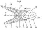
- Fig. 1
- eine erfindungsgemäße Einrichtung zur Befestigung von Streben zur Halterung eines Radschützers in schematisch vereinfachter Darstellung im teilweisen Längsschnitt;
- Fig. 2
- einen vertikalschnitt durch die erfindungsgemäße Einrichtung von Fig. 1;
- Fig. 3
- eine entsprechende Ansicht dieser Einrichtung.
- Fig. 1
- a device according to the invention for fastening struts for holding a wheel protector in a schematically simplified representation in partial longitudinal section;
- Fig. 2
- a vertical section through the inventive device of Fig. 1;
- Fig. 3
- a corresponding view of this facility.
Die erfindungsgemäße Einrichtung zur Befestigung von Streben
zur Halterung eines Radschützers gemäß Fig. 1 umfaßt ein als
Anschlußteil 14 ausgeführtes erstes Teil mit einem
Mittelstück 17, von dem aus sich radial nach außen hin zwei
Aufnahmen 18, 19 erstrecken, die zumindest abschnittsweise
etwa rohrförmig sind, um jeweils Teilstücke 15, 16 des
Strebendrahtes aufzunehmen, wobei letztere ebenso wie die
Aufnahmen einen spitzen Winkel einschließen. Man erkennt
weiterhin, daß die beiden Enden der Teilstücke 15, 16 der
Strebe in dem Anschlußteil 14 zu einer dort gebogenen
durchgehenden einzigen Sicherheitsstrebe verbunden sind,
wobei der gebogene Abschnitt der Strebe mit 15a bezeichnet
ist. Diese Strebe wird in dem Anschlußteil 14 in den
Aufnahmen 18, 19 und auch in dem Mittelstück 17 allseitig
umschlossen und eingefasst.The device according to the invention for fastening
Zu der zu den Teilstücken 15, 16 gegenüberliegenden Seite hin
erstreckt sich von dem Mittelstück 17 aus eine Anformung 21
des Anschlußteils 14, wobei diese Anformung 21 in dem
vorliegenden Ausführungsbeispiel jeweils einen stumpfen
Winkel mit den beiden Aufnahmen 18, 19 einnimmt. Diese
Anformung 21 hat in dem abgebildeten Ausführungsbeispiel eine
innen kugelförmige beziehungsweise teilkugelförmige Aufnahme
22, in die ein als Steckfortsatz 23 ausgebildeteter Abschnitt
eines als Einsteckteils 20 ausgebildeten zweiten Teils
einschiebbar ist. Die Einsteckrichtung des Steckfortsatzes 23
in die teilkugelförmige Aufnahme 22 des Anschlußteils 14 ist
in Fig. 1 durch den Pfeil gekennzeichnet.Towards the side opposite to the
Man erkennt weiterhin, daß das Einsteckteil 20 am anderen
Ende ein am Steckfortsatz 23 angeformtes Ringteil 24
aufweist. Dieses Ringteil 24 kann man über eine
Schraubverbindung an der Anformung einer Vorderradgabel eines
Fahrrads anschrauben, was an sich aus dem Stand der Technik
bekannt ist und deshalb in der Zeichnung Fig. 1 nicht
dargestellt ist. Dazu hat das Ringteil 24 eine konzentrische
Mittelbohrung 24a, die eine Schraube oder auch ein anderes
geeignetes Befestigungselement aufnehmen kann. Der
Steckfortsatz 23 wird zur Verbindung des Einsteckteils 20 mit
dem Anschlußteil 14 in die Aufnahme 22 eingesteckt, die
entsprechend diesem teilkugelförmig ausgebildet ist. Dabei
ergibt sich eine Rastverbindung, die bis zu einer bestimmten
vorgegebenen Belastungsgrenze fest und auf Zug in Richtung
entgegen des in Fig. 1 eingezeichneten Pfeils belastbar ist.
Jedoch dann, wenn die Zugkraft, die über die Streben 15, 16
entgegen der Pfeilrichtung von Fig. 1 einwirkt, Einsteckteil
20 und Anschlußteil 14 auseinanderzieht und eine vorgegebene
Grenzbelastung überschritten wird, löst sich die
Rastverbindung. Dies ist der Effekt der gewünschten
Sicherheitsbefestigung der Sicherheitsstreben 15, 16, die vom
Radschützer (nicht dargestellt) des Fahrrads kommen, an der
Vorderradgabel (nicht dargestellt) des Fahrrads und somit
letztendlich am Rahmen des Fahrrads.It can also be seen that the
Wie man aus der Zeichnung erkennen kann, ist die
teilkugelförmige Aufnahme 22 des Anschlußteils 14 im
Querschnitt des Anschlußteils gesehen so ausgebildet, daß sie
einen Umfangsbereich von vorzugsweise mehr als 180°
umschließt, beispielsweise wie in der Zeichnung einen
Umfangsbereich von etwa 230° entsprechend dem eingezeichneten
Winkel α. Dabei kommt es natürlich auf die Elastizität des
Materials an. Davon ist abhängig, bei welcher Zugkraft die
beiden Schenkel des Anschlußteils, die innenseitig die
Aufnahme 22 bilden, so auseinanderspreizen, daß der
teilkugelförmige Bereich des Steckfortsatzes 23 des
Einsteckteils 20 aus der Aufnahme 22 herausgezogen werden
kann. Neben der Elastizität des verwendeten Materials spielt
dann auch der Umfangsbereich gemäß dem Winkel α eine Rolle
mit dem die teilkugelförmige Aufnahme 22 den Steckfortsatz 23
übergreift, wobei einleuchtet, daß dieser Umfangsbereich
oberhalb von 180° liegen sollte.As you can see from the drawing, it is
Partially
Die Besonderheit bei der erfindungsgemäßen Einrichtung
gegenüber dem Stand der Technik liegt darin, daß nicht nur
ein Lösen zwischen dem Einsteckteil 20 und dem Anschlußteil
14 bei Auftreten einer einen bestimmten Grenzwert
überschreitenden Zugverbindung möglich ist, sondern daß auch
zwischen dem Einsteckteil 20 und dem Anschlußteil 14 eine
kugelgelenkartige Verbindung besteht, so daß auch ein Lösen
der Rastverbindung problemlos erfolgt, wenn die auftretenden
Zugkräfte nicht in Richtung der Verbindungsachse A zwischen
Anschlußteil 14 und Einsteckteil 20 wirken. Des weiteren wird
erreicht, daß man bei dieser Art der Verrastung nicht
zwischen rechts und links unterscheiden muß, wodurch sich
logistische Vorteile beim Hersteller und beim
Fahrradhersteller ergeben.The special feature of the device according to the invention
compared to the prior art is that not only
a loosening between the
Claims (9)
Applications Claiming Priority (2)
| Application Number | Priority Date | Filing Date | Title |
|---|---|---|---|
| DE29810177U | 1998-06-06 | ||
| DE29810177U DE29810177U1 (en) | 1998-06-06 | 1998-06-06 | Device for fastening struts to hold a wheel guard |
Publications (2)
| Publication Number | Publication Date |
|---|---|
| EP0962382A1 true EP0962382A1 (en) | 1999-12-08 |
| EP0962382B1 EP0962382B1 (en) | 2005-03-16 |
Family
ID=8058201
Family Applications (1)
| Application Number | Title | Priority Date | Filing Date |
|---|---|---|---|
| EP99110866A Expired - Lifetime EP0962382B1 (en) | 1998-06-06 | 1999-06-07 | Fixing device for the mudguard of a bicycle |
Country Status (4)
| Country | Link |
|---|---|
| EP (1) | EP0962382B1 (en) |
| AT (1) | ATE290978T1 (en) |
| DE (2) | DE29810177U1 (en) |
| DK (1) | DK0962382T3 (en) |
Cited By (4)
| Publication number | Priority date | Publication date | Assignee | Title |
|---|---|---|---|---|
| EP1439115A2 (en) | 2003-01-17 | 2004-07-21 | sks metaplast Scheffer-Klute GmbH | Device for fixing struts for the fixation of a wheel guard to the frame of a bicycle |
| EP1466822A3 (en) * | 2003-04-08 | 2005-07-13 | Orion-Italy Componenti Biciclette Srl | Device for fixing and quick releasing the support stays of a bicycle's mudguard |
| NL1037218C2 (en) * | 2009-08-21 | 2011-02-22 | Curana Invest Bvba | SAFETY CONNECTION FOR A BIKE Fender. |
| IT201900002265A1 (en) | 2019-02-15 | 2020-08-15 | Eurofender S R L | DEVICE FOR FIXING THE FENDER RODS TO THE BICYCLE FRAME |
Families Citing this family (3)
| Publication number | Priority date | Publication date | Assignee | Title |
|---|---|---|---|---|
| IT245384Y1 (en) * | 1998-09-18 | 2002-03-20 | San Giorgio Snc Di De Poli Liv | FAST FASTENING AND RELEASING DEVICE OF THE SUPPORT RODS OF A FENDER FOR BICYCLES. |
| GB9820590D0 (en) * | 1998-09-23 | 1998-11-11 | Webb Ronald R | Cycle mudguard stay release clip |
| ITUA20164232A1 (en) * | 2016-06-09 | 2017-12-09 | tubus carrier systems GmbH | FENDER HOLDER ARM FOR BICYCLES AND SIMILAR FENDERS |
Citations (3)
| Publication number | Priority date | Publication date | Assignee | Title |
|---|---|---|---|---|
| DE4232539A1 (en) * | 1992-09-29 | 1994-03-31 | Engelbert Wiener Gmbh & Co Kg | Bicycle with detachable mudguards - has mudguards secured by plug-in-type connectors to front fork and rear top plate |
| EP0694469A1 (en) * | 1994-07-29 | 1996-01-31 | ESGE-Marby GmbH + Co. KG. | Mudguard arrangement |
| EP0803429A2 (en) | 1996-04-26 | 1997-10-29 | sks-metaplast SCHEFFER-KLUTE GMBH | Fixing device for a mudguard of a bicycle |
-
1998
- 1998-06-06 DE DE29810177U patent/DE29810177U1/en not_active Expired - Lifetime
-
1999
- 1999-06-07 DE DE59911751T patent/DE59911751D1/en not_active Expired - Lifetime
- 1999-06-07 AT AT99110866T patent/ATE290978T1/en active
- 1999-06-07 EP EP99110866A patent/EP0962382B1/en not_active Expired - Lifetime
- 1999-06-07 DK DK99110866T patent/DK0962382T3/en active
Patent Citations (3)
| Publication number | Priority date | Publication date | Assignee | Title |
|---|---|---|---|---|
| DE4232539A1 (en) * | 1992-09-29 | 1994-03-31 | Engelbert Wiener Gmbh & Co Kg | Bicycle with detachable mudguards - has mudguards secured by plug-in-type connectors to front fork and rear top plate |
| EP0694469A1 (en) * | 1994-07-29 | 1996-01-31 | ESGE-Marby GmbH + Co. KG. | Mudguard arrangement |
| EP0803429A2 (en) | 1996-04-26 | 1997-10-29 | sks-metaplast SCHEFFER-KLUTE GMBH | Fixing device for a mudguard of a bicycle |
Cited By (7)
| Publication number | Priority date | Publication date | Assignee | Title |
|---|---|---|---|---|
| EP1439115A2 (en) | 2003-01-17 | 2004-07-21 | sks metaplast Scheffer-Klute GmbH | Device for fixing struts for the fixation of a wheel guard to the frame of a bicycle |
| EP1439115A3 (en) * | 2003-01-17 | 2007-06-27 | sks metaplast Scheffer-Klute GmbH | Device for fixing struts for the fixation of a wheel guard to the frame of a bicycle |
| EP1466822A3 (en) * | 2003-04-08 | 2005-07-13 | Orion-Italy Componenti Biciclette Srl | Device for fixing and quick releasing the support stays of a bicycle's mudguard |
| NL1037218C2 (en) * | 2009-08-21 | 2011-02-22 | Curana Invest Bvba | SAFETY CONNECTION FOR A BIKE Fender. |
| EP2287068A1 (en) * | 2009-08-21 | 2011-02-23 | Curana Invest BVBA | Safety connection device for a bicycle mudguard |
| IT201900002265A1 (en) | 2019-02-15 | 2020-08-15 | Eurofender S R L | DEVICE FOR FIXING THE FENDER RODS TO THE BICYCLE FRAME |
| EP3696063A1 (en) | 2019-02-15 | 2020-08-19 | Eurofender s.r.l. | Device for attaching mudguard stays to a bicycle frame |
Also Published As
| Publication number | Publication date |
|---|---|
| DK0962382T3 (en) | 2005-07-11 |
| DE29810177U1 (en) | 1998-08-13 |
| DE59911751D1 (en) | 2005-04-21 |
| ATE290978T1 (en) | 2005-04-15 |
| EP0962382B1 (en) | 2005-03-16 |
Similar Documents
| Publication | Publication Date | Title |
|---|---|---|
| DE19707634B4 (en) | holding system | |
| DE69303001T2 (en) | Pipe coupling device | |
| DE10032010C1 (en) | Connection fitting for a pipe etc. through a housing wall has a division near the angled support surface for the limit ring to allow for large wall thickness differences | |
| DE69610507T2 (en) | CONNECTION SYSTEM FOR ACTUATING CABLES | |
| DE3811757A1 (en) | Device for connecting a wheel rim to an axle of a wheel | |
| DE3224589A1 (en) | LUGGAGE RACK FOR A TWO-WHEEL | |
| DE9406076U1 (en) | Fastening device for rod-shaped objects | |
| DE19650864B4 (en) | Arrangement for fastening a lighting device to a vehicle part | |
| DE2822259C2 (en) | Quick coupling for tubular lines, in particular for liquids | |
| EP0962382B1 (en) | Fixing device for the mudguard of a bicycle | |
| DE19607572B4 (en) | Clip for attaching pipes and the like | |
| DE3713200A1 (en) | CONNECTOR | |
| DE69821974T2 (en) | Device for holding objects together | |
| DE9013188U1 (en) | Mounting device for mounting a ring lock on a bicycle frame | |
| EP0803429B1 (en) | Fixing device for a mudguard of a bicycle | |
| DE29610385U1 (en) | Plug coupling for pipes | |
| EP1439115B1 (en) | Device for fixing struts for the fixation of a wheel guard to the frame of a bicycle | |
| DE3343554C2 (en) | Fastening device | |
| DE19526868C2 (en) | Securing element for multi-part connection units such as screw connections and the like | |
| DE8520830U1 (en) | Wire tension clamp | |
| DE69606754T2 (en) | System for holding the position of a clamping element | |
| DE19615487C1 (en) | Self-securing lock bolt for articulated connection of clutch pedal with transmission cylinder | |
| DE4445357A1 (en) | Connector for pressurised air line to pneumatic brake mechanism | |
| DE202018104983U1 (en) | Thru-axle with coupling adapter | |
| DE9012176U1 (en) | Coupling adapter for connecting to a vehicle trailer coupling |
Legal Events
| Date | Code | Title | Description |
|---|---|---|---|
| PUAI | Public reference made under article 153(3) epc to a published international application that has entered the european phase |
Free format text: ORIGINAL CODE: 0009012 |
|
| AK | Designated contracting states |
Kind code of ref document: A1 Designated state(s): AT BE CH DE DK FR IT LI NL SE |
|
| AX | Request for extension of the european patent |
Free format text: AL;LT;LV;MK;RO;SI |
|
| 17P | Request for examination filed |
Effective date: 20000608 |
|
| AKX | Designation fees paid |
Free format text: AT BE CH DE DK FR IT LI NL SE |
|
| GRAH | Despatch of communication of intention to grant a patent |
Free format text: ORIGINAL CODE: EPIDOS IGRA |
|
| GRAJ | Information related to disapproval of communication of intention to grant by the applicant or resumption of examination proceedings by the epo deleted |
Free format text: ORIGINAL CODE: EPIDOSDIGR1 |
|
| GRAP | Despatch of communication of intention to grant a patent |
Free format text: ORIGINAL CODE: EPIDOSNIGR1 |
|
| GRAS | Grant fee paid |
Free format text: ORIGINAL CODE: EPIDOSNIGR3 |
|
| GRAA | (expected) grant |
Free format text: ORIGINAL CODE: 0009210 |
|
| AK | Designated contracting states |
Kind code of ref document: B1 Designated state(s): AT BE CH DE DK FR IT LI NL SE |
|
| REG | Reference to a national code |
Ref country code: CH Ref legal event code: EP |
|
| REF | Corresponds to: |
Ref document number: 59911751 Country of ref document: DE Date of ref document: 20050421 Kind code of ref document: P |
|
| REG | Reference to a national code |
Ref country code: SE Ref legal event code: TRGR |
|
| REG | Reference to a national code |
Ref country code: DK Ref legal event code: T3 |
|
| PLBE | No opposition filed within time limit |
Free format text: ORIGINAL CODE: 0009261 |
|
| STAA | Information on the status of an ep patent application or granted ep patent |
Free format text: STATUS: NO OPPOSITION FILED WITHIN TIME LIMIT |
|
| 26N | No opposition filed |
Effective date: 20051219 |
|
| ET | Fr: translation filed | ||
| REG | Reference to a national code |
Ref country code: FR Ref legal event code: PLFP Year of fee payment: 17 |
|
| PGFP | Annual fee paid to national office [announced via postgrant information from national office to epo] |
Ref country code: DK Payment date: 20150618 Year of fee payment: 17 Ref country code: DE Payment date: 20150630 Year of fee payment: 17 Ref country code: SE Payment date: 20150618 Year of fee payment: 17 Ref country code: CH Payment date: 20150618 Year of fee payment: 17 |
|
| PGFP | Annual fee paid to national office [announced via postgrant information from national office to epo] |
Ref country code: NL Payment date: 20150618 Year of fee payment: 17 Ref country code: AT Payment date: 20150619 Year of fee payment: 17 Ref country code: IT Payment date: 20150623 Year of fee payment: 17 Ref country code: BE Payment date: 20150618 Year of fee payment: 17 Ref country code: FR Payment date: 20150619 Year of fee payment: 17 |
|
| PG25 | Lapsed in a contracting state [announced via postgrant information from national office to epo] |
Ref country code: BE Free format text: LAPSE BECAUSE OF NON-PAYMENT OF DUE FEES Effective date: 20160630 |
|
| REG | Reference to a national code |
Ref country code: DE Ref legal event code: R119 Ref document number: 59911751 Country of ref document: DE |
|
| REG | Reference to a national code |
Ref country code: DK Ref legal event code: EBP Effective date: 20160630 |
|
| REG | Reference to a national code |
Ref country code: CH Ref legal event code: PL Ref country code: SE Ref legal event code: EUG |
|
| REG | Reference to a national code |
Ref country code: NL Ref legal event code: MM Effective date: 20160701 |
|
| REG | Reference to a national code |
Ref country code: AT Ref legal event code: MM01 Ref document number: 290978 Country of ref document: AT Kind code of ref document: T Effective date: 20160607 |
|
| PG25 | Lapsed in a contracting state [announced via postgrant information from national office to epo] |
Ref country code: SE Free format text: LAPSE BECAUSE OF NON-PAYMENT OF DUE FEES Effective date: 20160608 |
|
| REG | Reference to a national code |
Ref country code: FR Ref legal event code: ST Effective date: 20170228 |
|
| PG25 | Lapsed in a contracting state [announced via postgrant information from national office to epo] |
Ref country code: FR Free format text: LAPSE BECAUSE OF NON-PAYMENT OF DUE FEES Effective date: 20160630 Ref country code: DE Free format text: LAPSE BECAUSE OF NON-PAYMENT OF DUE FEES Effective date: 20170103 Ref country code: LI Free format text: LAPSE BECAUSE OF NON-PAYMENT OF DUE FEES Effective date: 20160630 Ref country code: CH Free format text: LAPSE BECAUSE OF NON-PAYMENT OF DUE FEES Effective date: 20160630 |
|
| PG25 | Lapsed in a contracting state [announced via postgrant information from national office to epo] |
Ref country code: NL Free format text: LAPSE BECAUSE OF NON-PAYMENT OF DUE FEES Effective date: 20160701 Ref country code: AT Free format text: LAPSE BECAUSE OF NON-PAYMENT OF DUE FEES Effective date: 20160607 |
|
| PG25 | Lapsed in a contracting state [announced via postgrant information from national office to epo] |
Ref country code: IT Free format text: LAPSE BECAUSE OF NON-PAYMENT OF DUE FEES Effective date: 20160607 |
|
| PG25 | Lapsed in a contracting state [announced via postgrant information from national office to epo] |
Ref country code: DK Free format text: LAPSE BECAUSE OF NON-PAYMENT OF DUE FEES Effective date: 20160630 |