EP0962383A2 - Method for analyzing friction reduction effects of bubbles in a ship - Google Patents
Method for analyzing friction reduction effects of bubbles in a ship Download PDFInfo
- Publication number
- EP0962383A2 EP0962383A2 EP99401281A EP99401281A EP0962383A2 EP 0962383 A2 EP0962383 A2 EP 0962383A2 EP 99401281 A EP99401281 A EP 99401281A EP 99401281 A EP99401281 A EP 99401281A EP 0962383 A2 EP0962383 A2 EP 0962383A2
- Authority
- EP
- European Patent Office
- Prior art keywords
- equation
- bubble
- constant
- flow
- wall
- Prior art date
- Legal status (The legal status is an assumption and is not a legal conclusion. Google has not performed a legal analysis and makes no representation as to the accuracy of the status listed.)
- Withdrawn
Links
Images






Classifications
-
- B—PERFORMING OPERATIONS; TRANSPORTING
- B63—SHIPS OR OTHER WATERBORNE VESSELS; RELATED EQUIPMENT
- B63B—SHIPS OR OTHER WATERBORNE VESSELS; EQUIPMENT FOR SHIPPING
- B63B1/00—Hydrodynamic or hydrostatic features of hulls or of hydrofoils
- B63B1/32—Other means for varying the inherent hydrodynamic characteristics of hulls
- B63B1/34—Other means for varying the inherent hydrodynamic characteristics of hulls by reducing surface friction
- B63B1/38—Other means for varying the inherent hydrodynamic characteristics of hulls by reducing surface friction using air bubbles or air layers gas filled volumes
-
- B—PERFORMING OPERATIONS; TRANSPORTING
- B63—SHIPS OR OTHER WATERBORNE VESSELS; RELATED EQUIPMENT
- B63B—SHIPS OR OTHER WATERBORNE VESSELS; EQUIPMENT FOR SHIPPING
- B63B71/00—Designing vessels; Predicting their performance
-
- G—PHYSICS
- G01—MEASURING; TESTING
- G01N—INVESTIGATING OR ANALYSING MATERIALS BY DETERMINING THEIR CHEMICAL OR PHYSICAL PROPERTIES
- G01N13/00—Investigating surface or boundary effects, e.g. wetting power; Investigating diffusion effects; Analysing materials by determining surface, boundary, or diffusion effects
-
- G—PHYSICS
- G01—MEASURING; TESTING
- G01N—INVESTIGATING OR ANALYSING MATERIALS BY DETERMINING THEIR CHEMICAL OR PHYSICAL PROPERTIES
- G01N19/00—Investigating materials by mechanical methods
- G01N19/02—Measuring coefficient of friction between materials
-
- G—PHYSICS
- G01—MEASURING; TESTING
- G01N—INVESTIGATING OR ANALYSING MATERIALS BY DETERMINING THEIR CHEMICAL OR PHYSICAL PROPERTIES
- G01N13/00—Investigating surface or boundary effects, e.g. wetting power; Investigating diffusion effects; Analysing materials by determining surface, boundary, or diffusion effects
- G01N13/02—Investigating surface tension of liquids
- G01N2013/0216—Investigating surface tension of liquids by measuring skin friction or shear force
-
- G—PHYSICS
- G01—MEASURING; TESTING
- G01N—INVESTIGATING OR ANALYSING MATERIALS BY DETERMINING THEIR CHEMICAL OR PHYSICAL PROPERTIES
- G01N13/00—Investigating surface or boundary effects, e.g. wetting power; Investigating diffusion effects; Analysing materials by determining surface, boundary, or diffusion effects
- G01N13/02—Investigating surface tension of liquids
- G01N2013/0241—Investigating surface tension of liquids bubble, pendant drop, sessile drop methods
- G01N2013/0266—Bubble methods
-
- Y—GENERAL TAGGING OF NEW TECHNOLOGICAL DEVELOPMENTS; GENERAL TAGGING OF CROSS-SECTIONAL TECHNOLOGIES SPANNING OVER SEVERAL SECTIONS OF THE IPC; TECHNICAL SUBJECTS COVERED BY FORMER USPC CROSS-REFERENCE ART COLLECTIONS [XRACs] AND DIGESTS
- Y02—TECHNOLOGIES OR APPLICATIONS FOR MITIGATION OR ADAPTATION AGAINST CLIMATE CHANGE
- Y02T—CLIMATE CHANGE MITIGATION TECHNOLOGIES RELATED TO TRANSPORTATION
- Y02T70/00—Maritime or waterways transport
- Y02T70/10—Measures concerning design or construction of watercraft hulls
Definitions
- the present invention relates to a method for analyzing the effects of interposing bubbles at the ship-water interface on reducing the skin-friction of a cruising ship.
- the present inventors had disclosed an analytical method for obtaining dynamics of bubbles on the hull surface based on the mixing length theory, in a Japanese Patent Application, First Publication, Hei 8-144646. This was followed by a Japanese Patent Application, First Publication, Hei 9-292999, in which a technique was disclosed to simulate the bubble distribution patterns on hull surfaces. It was further disclosed in Japanese Patent Applications, First Publications, Hei 9-142818 and Hei 10-55453 (U.S.
- Patent Application No.078,950 that a turbulent flow model in the turbulent boundary layer near the hull surface can be constructed by extending the mixing length theory to a bubbly flow field in the turbulent flow model, it offered an analytical methodology to logically explain past experimental results, and demonstrated that the friction reduction effects in different flow fields can be analytically reproduced, by adjusting the operative wall constant ⁇ 1 in the wall law for bubbly flow to indicate the bubble mixing length, in accordance with the extent of flow fields, i.e., the thickness of the turbulent boundary layer produced.
- the object has been achieved in a method for analyzing effects of generating bubble jets in a flow field near a ship surface on reducing skin-friction in a cruising ship comprising the steps of: obtaining a shear stress decrement ⁇ ⁇ produced by having a bubble in the flow field in terms of a resistive force ⁇ R ⁇ acting on the bubble derived from movements of the bubble in a fluid flow direction, x-direction, along the cruising ship as well as in a direction at right angles to a ship wall surface, y-direction, in accordance with a definition of a high frequency band region in which a product of a bubble time-constant T and a turbulence frequency ⁇ L in the flow field is greater than 1; obtaining an operative wall constant ⁇ 1 in the wall law when there is a bubble having a parametric bubble diameter d b , by assuming that the shear stress decrement is generated by a decrease in a mixing length; and obtaining a solution for skin-friction
- the object has also been achieved in a method for analyzing effects of generating bubble jets in a flow field near a ship surface on reducing skin-friction in a cruising ship comprising the steps of: performing a Fourier transform of kinetic equations (1) and (2) for a bubble moving in x- and y-directions, representing a fluid flow direction and a direction at right angles to the ship surface, respectively, in terms of an added mass of a bubble m A , a bubble diameter d b , a dynamic liquid viscosity coefficient ⁇ L , and obtaining an expression for a gain in x-direction G x and an expression for a gain in y-direction G y comprised by a bubble time-constant T and a turbulence frequency ⁇ L , based on equations (3) and (4) respectively; obtaining from equation (16) a resistive force ⁇ R ⁇ acting on a bubble in a high frequency band region where a product of a bubble time-constant T and a tur
- Figure 1 is a conceptual drawing of the turbulent flow model in a first embodiment.
- Figure 2 is a schematic drawing of a near-wall bubble in a flow field in the first embodiment.
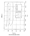
- Figure 3 is a graph showing a trend of a skin-friction ratio C f /C f0 to vary with average void fraction ⁇ m for each frequency band in the first embodiment.
- Figure 4 is a graph showing the effects of adjusting the empirical constant a in the skin-friction ratio C f /C f0 in the first embodiment.
- Figure 5 is a first graph showing the verification results of the first embodiment.
- Figure 6 is a second graph showing the verification results of the first embodiment.
- Figure 7 is a third graph showing the verification results of the first embodiment.
- Figure 8 is a fourth graph showing the results of verification of the first embodiment.
- Figure 9 a conceptual drawing of the turbulent flow model in the second embodiment.
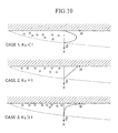
- Figure 10 is a schematic drawing to show the variation in the pattern of void fraction distribution in the second embodiment.
- Figure 11 is a flowchart to show the steps for computing the skin-friction ratio C f /C f0 in the second embodiment.
- Figure 12 is a graph showing the verification results of void fraction distribution in the second embodiment.
- Figure 13 a graph showing the verification results of void fraction distribution in a two-dimensional channel in the second embodiment.
- Figure 14 is a first graph showing the results of verification of the second embodiment.
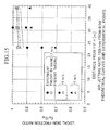
- Figure 15 is a second graph showing the results of verification of the second embodiment.
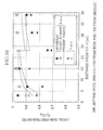
- Figure 16 is a third graph showing the results of verification of the second embodiment.
- Figure 17 is a fourth graph showing the results of verification of the second embodiment.
- this embodiment presents analyses of bubbly flow in a boundary layer beneath a two-dimensional plate (for example, the bottom surface of a ship) in terms of a turbulent flow model which includes y-direction and x-direction at right angles to the y-direction.
- movements of the bubbles ejected from the hull surface (bottom wall surface) will be analyzed in the perpendicular direction to the wall surface (y-direction) and in the fluid flow direction along the hull surface (x-direction).
- Bubbles ejected into the turbulent flow layer will move in response to the velocity of turbulent flow of the liquid phase.
- Density of air is about 1/10 3 of that for water, and its momentum is negligibly small compared with the added inertial force.
- the ejected bubbles do not respond immediately to the fluid velocity, and a differential velocity is produced between the air and liquid phases.
- the differential velocity creates a resistive force on the bubble, and a reactive force in the liquid phase.
- the kinetic equations of motion of the bubble are as follows: and where m A is an added mass of a single bubble, ⁇ L is the viscosity coefficient of the liquid phase, d b is the diameter of the bubble, u' L is the turbulent velocity of the liquid in x-direction, ⁇ ' L is the turbulent velocity of the liquid in y-direction, the superscript ' refers to a change from an instantaneous average velocity (turbulent velocity) and the subscript L indicates that the property relates to the liquid phase.
- Equation (3) By subjecting these equations (1) and (2) to a Fourier transform, squared average gains of the relative displacement velocities in x- and y-directions corresponding to the squared average turbulent velocities in x- and y-directions can be obtained using equations (3) and (4) shown below.
- a bar-crown indicates time-averaging and a circumflex-crown ⁇ , for example, denotes a squared average value.
- ⁇ L refers to the angular frequency of the turbulent flow in a flow field
- T a time-constant for a bubble which is given by equation (5) given below.
- squared average values are assumed to be the representative value. For example, when the bubble exists in the upper half region of the path A-A, squared average value for the resistive force ⁇ R v for the bubble is expressed by equation (6) given below.
- the regions given by these conditional relations (8) ⁇ (10) are defined as low frequency band region, middle frequency band region and high frequency band region, respectively. Motions in the middle frequency band region are most complex to solve and require rigorous solutions based on actual operating conditions. If prominent frequencies are known, they may be solved by series expansion and other techniques, but this region is not dealt with in this embodiment. On the other hand, structural equations in the low or high frequency band regions are simpler to treat so that parametric dependency can be better anticipated in many cases. Therefore, the following presentation will be concerned only with the low and high frequency band regions.
- Equation (12) Equation (12): where l mo is the mixing length corresponding to the mean free path of a near-wall bubble. Strictly speaking, however, l mo does not correspond exactly to the mean free path of a bubble, because the apparent mixing length is affected by the amount of decrement in the shear stress caused by the resistive force of the bubble.
- Equation (13) The magnitude of the gas mixing length l mo in the near-wall region is given by equation (13). l mo ⁇ ⁇ y where ⁇ is a normal wall constant when a bubble is not present (von Karman constant) and a value of 0.41 is adopted.
- An average length for one bubble in its spatial element (that is, an average length of free movement for one bubble on the wall surface) can be expressed as ( ⁇ /6 ⁇ w ) 1/2 d b for a given void fraction ⁇ w so that the shear stress decrement ⁇ t caused by the resistive force of the bubble is expressed as in equation (17).
- ⁇ t 81 ⁇ 2 ⁇ L ⁇ L T * L d b ⁇ w ⁇ u L ⁇ y
- the shear stress should include an increment factor, as well as a decrement factor, caused by kinetic mass exchange taking place between the water and the bubble. It can be considered that when a bubble moves in the fluid, water of the equal volume flows into the space vacated by the bubble. Therefore, the movement of a bubble in the turbulent boundary layer can be considered to be equivalent to an added movement of water of the same volume.
- the mechanism of additional stress generation is the same as the Reynolds stress generated by the movement of liquid particles, therefore, shear stress increment ⁇ m cab be expressed as in equation (18).
- the shear stress ⁇ w on the wall surface can be expressed by equation (20).
- ⁇ m is an apparent viscosity coefficient (a coefficient in molecular viscosity term).
- equation (26) can be re-expressed as in equation (27).
- l mb ⁇ L / U ⁇ d b / a ⁇ w y
- a 2 81 2 ⁇ 2 b 2
- Equation (27) the effects of a bubble can be expressed by revising the normal wall constant ⁇ for non-bubbly flow.
- Parametric variables are summarized in the following equations (29) ⁇ (32).
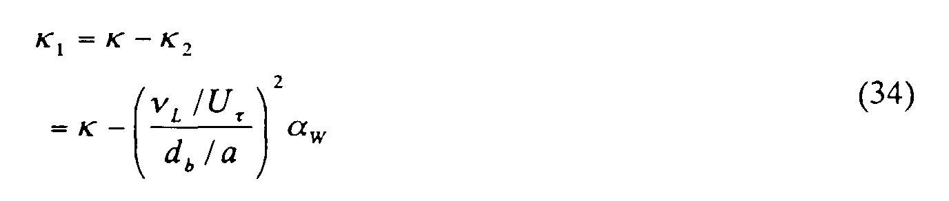
- the operative wall constant ⁇ 1 for bubbly now can be expressed by subtracting the revised wall constant ⁇ 2 from the normal wall constant ⁇ for non-bubbly flow (i.e., single phase) according to equation (34).
- Equation (34) has an extremely interesting structure. Control parameters for turbulent flow are contained inside the bracket, and are expressed by a ratio of the size of viscous sublayer and the size of the bubble (denominator d b / a is proportional to the bubble diameter). From equation (25), it can be seen that the extent of turbulent flow is deeply related to the extent of viscous sublayer, and therefore, the analytical model in the present embodiment suggests that the numerical simulation should be based on the ratio of the bubble size and the extent of the turbulent flow field. Looking only at this result, the present model is not inconsistent with past experimental observations that turbulence control is achieved when the bubble size is small relative to the extent of turbulent flow field.
- the shear stress decrement ⁇ t caused by the bubble is of the order of ( T ⁇ L ) 2 and is very small. Therefore, the shear stress ⁇ W is given by adding the increment ⁇ m to the shear stress ⁇ W0 for non-bubbly flow to yield an equation (35).
- equations (36) and (40) above can be re-written as equations (44), (45).
- 2 C f 0 1 ⁇ log ⁇ 0 + + B
- 2 C f 1 ⁇ 1 log C f C f 0 ⁇ 0 + + B
- equation (48) is obtained.
- Equation (48) The term ( C f /C f0 ) 1/2 in equation (48) is expanded about 1, and taking the first-order terms, the following equation (49) is obtained.
- Equation (50) is substituted in equation (33) to obtain ⁇ 2 , which is substituted in equation (34) to obtain ⁇ 1 , and the ⁇ 1 so obtained is substituted in equation (49) to solve for the skin-friction ratio Cf/C f0 to produce the following equation (51).
- equation (51) ⁇ 10 , ⁇ 20 , ⁇ 0 + are respectively given by equations (52) ⁇ (54) given below.
- ⁇ L ⁇ where ⁇ L relates to the single liquid phase and ⁇ relates to a two-phase mixture of liquid and bubble.
- equation (55) was evaluated using a forty meter model ship (40-m model ship) to produce data that will be examined in detail below.
- the empirical constant a used in equation (27) was determined using the experimental data obtained by Guin et al. (1996).
- the turbulent boundary layer in the stern-side of the 40-m model ship has a thickness of several hundred mm, which is sufficiently greater than the diameter of the bubbles of about 2 mm, and the float effect of the bubble is greater than the dispersion effect caused by turbulence. Therefore, the amount of bubbles congregating near the wall surface can be estimated roughly from the main fluid velocity and the air flow rate.
- Near-wall void fraction of the 40-m model ship was considered as follows.
- the center velocity of a small-scale vortex generated by bubble ejection is assumed to be a half of the main fluid velocity, i.e., 0.5 U (refer to Kobayashi, 1983), and applying the 1/7 multiplier rule, the position of the center of the small-scale vortex is about 0.1 ⁇ from the surface of the wall.
- the end of the vortex is twice this value, i.e., 0.2 ⁇ , and therefore, it may be considered that the region most relevant in generating turbulent flow stress is located between 0.1 ⁇ -0.2 ⁇ from the wall surface.
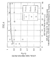
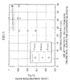
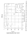
- Verification results are shown in Figures 4-7.
- experimental results of skin-friction ratio C f /C f0 and theoretical results of C f /C f0 obtained from equation (55) are compared in Figure 4, when the bubbles are jetted from the bow of the model ship.
- Figure 5 compares the same when the bubbles are jetted from the center of the bottom surface.
- Figure 6 compares the same when the bubbles are jetted from the bow as well as from the center of the bottom surface.
- Figure 7 compares the cases of using the flow rate of air ejected into water as a parameter, when the bubbles are jetted from the bow.
- equation (55) for evaluating the effects of skin-friction reduction was developed by re-examining more rigorously some of the variables which were not fully examined in the technique used in our previous work.
- shear stress increment ⁇ m is small relative to the shear stress decrement ⁇ t .
- the increment ⁇ m cannot be ignored and, contrastingly, in the low frequency band region, the effect of the shear stress increment becomes predominant.
- response of the bubble movement is poor and the movement is small so that there is little kinetic mass exchange, and the effects of resistive force of the bubbles on the shear stress reduction become high.
- there is high activity in kinetic mass exchange there is high activity in kinetic mass exchange, and the effect of shear stress increase becomes high.
- Figure 8 shows a conceptual summary of the tendency of the skin-friction ratio, C f /C f0 in the three frequency regions.
- the solution for the skin-friction ratio C f /C f0 was developed as in equation (55), by assuming that the operative wall constant ⁇ 1 for bubbly flow was obtained by subtracting the revised wall constant ⁇ 2 from the normal wall constant ⁇ for non-bubbly flow as in equation (34).
- Figure 9 shows a model for analyzing the movement of bubbles.
- An examination region bounded by points A, B, C and D is designated within the turbulent boundary layer, and is surrounded by four dispersing particles (1)-(4).
- the center of each bubble represents the center of movement of each bubble, and the dotted line represents a circular boundary of free movement of each bubble, and each diameter representing a respective mean free path. The distance between the centers is assumed to be equal to the mean free path.
- the distance between the centers may be expressed as cl b in terms of the mixing length l b of the gas phase and an empirical constant c .
- the constant c relates to a dispersion coefficient.
- the distance between the centers relates to a distance between the neighboring vortexes, and can be interpreted as a measure of the vortex length.
- Equation (57) relates to a flow flux induced by the turbulent velocities of bubble (2) and bubble (4) shown in Figure 9.
- the third term in equation (58) relates to a flow flux induced by the turbulent velocities of bubble (1) and bubble (3).
- equations (57), (58) are substituted in equation (56) to obtain equation (62).
- equation (63) leads to equation (64).
- equation (64) is designated as the governing equation for void fraction distribution.
- first and second terms relate to flow fluxes expressing dispersion caused by turbulence.
- the first term is considered to be related to liquid-controlled dispersion caused by the liquid turbulence while the second term is considered to be related to void-controlled dispersion.
- liquid phase mixing length l m0 ⁇ y 1- y ⁇
- equation (72) can be rewritten as follows.
- Equation (73) is a separable-variable differential equation, and a solution can be derived readily as follows.
- ⁇ K 1 y - K 0 +1 K 0 1- y ⁇
- K 0 and K 1 are given by equations (75) and (76), given respectively below, where ⁇ a ⁇ in equation (76) is an average void fraction in the turbulent boundary layer.
- K 0 9 ⁇ 1 3 U ⁇ g 2 c ⁇ L 3 4 d b a and
- K 0 and K 1 are parameters for determining the void fraction distribution, where K 0 specifies the peak position and K 1 specifies the overall size of the void fraction.
- Figure 10 is a graph showing how the local void fraction ⁇ in y -direction varies when the constant K 0 is altered.
- the parameter K 0 varies as the 4th power of the bubble diameter, so that the local void fraction ⁇ is very sensitive to changes in the bubble dimension.
- the empirical constant a also exerts a large influence on the parameter K 0 it is extremely difficult to unilaterally select a bubble size, which varies widely in reality, and to input some bubble diameter d b as a variable to estimate the void fraction distribution.
- the approach taken in this embodiment is to adjust the parameters K 0 , K 1 in the void fraction distribution equation (74) until the computed a matches with the actual void fraction distribution, and the value of K 0 so obtained is used in equation (75) to derive a value of ( d b / a ). Simultaneous equations are then established with equation (34) to develop an expression for skin-friction ratio C f /C f0 by two-way coupling approach.
- equation (75) an expression for one-way coupling can be conveniently developed by replacing the bubbly flow frictional velocity U ⁇ with the non-bubbly flow U ⁇ 0 , and replacing the constant ⁇ 1 for bubbly flow with ⁇ for non-bubbly flow.
- Figure 11 is a block diagram of the computational steps for one-way coupling and two-way coupling approaches. These expressions, one-way coupling and two-way coupling, are used in describing Lagrangian models, but they are useful also in describing the present computational models.
- One-way coupling approach is a method to perform computations related to bubbly fluid flow based on computed results related to bubbles
- two-way coupling approach is a method to perform computations related to bubbly fluid flow based on computed results related to bubbles, and feed back the results related to bubbly fluid flow to perform computations related to bubbles.
- the aspects of the model examined are determination of empirical constant c , evaluation of the method for approximation and the qualitative expressive ability of the model.
- Figure 13 shows the results in terms of the effects of average void fraction ⁇ m (based on the total width of the channel) on the skin-friction ratio C f /C f0 encountered in the fluid flowing within the channel. Equations (75), (76) were used to obtain void fractions which would duplicate the near-wall void fraction measured by Guin et al. The computed results using the two-way coupling approach (triangles) and those obtained using the one-way coupling approach (squares) are also shown in Figure 13. For reference purposes, results obtained by Madavan (1984) are also plotted in Figure 13.
- the near-wall void fraction ⁇ w can be obtained using turbulent layer average void fraction ⁇ a ⁇ according to equation (77).
- ⁇ w 2 ⁇ a ⁇
- Empirical constant c was assumed to be 0.01. All subsequent computations are based on this value.
- Figures 14 ⁇ 17 are graphs showing computed and measured results.
- Figure 14 shows the effects of the distance from the origin of bubble jet on the skin-friction ratio C f /C f0 for various ship speed values, when the bubbles are ejected from the nozzles on the bow-bottom of the ship.
- Figure 15 shows the same when the bubbles are ejected from the nozzles in the middle of the ship.
- Figure 16 shows the same when the bubbles are ejected from the nozzles at both the bow and the middle of the ship.
- Figure 17 shows the effects of the distance from the origin of the bubble jet on the skin-friction ratio C f /C f0 for various flow rates of gas jetting from the nozzles in the bow of the ship.
- a stability condition may mean that the closer the bubble is to the wall the larger the bubble volume. It may also be that an apparent viscosity of the fluid changes as a result of mixing with the bubbles so that bubbly flow may be a phenomenon similar to spreading of an adhered high-viscosity fluid mass over the ship wall surface.
- bubbly flow dynamics involves an ever-changing process of mixing of bubbles of various sizes in search of transient stability by collapsing and coalescing, leading to macroscopic adjustments in bubble sizes to achieve an ultimate dynamic equilibrium between void dispersion force and float force.
Landscapes
- Physics & Mathematics (AREA)
- Chemical & Material Sciences (AREA)
- Fluid Mechanics (AREA)
- Engineering & Computer Science (AREA)
- Combustion & Propulsion (AREA)
- Mechanical Engineering (AREA)
- Ocean & Marine Engineering (AREA)
- Life Sciences & Earth Sciences (AREA)
- Health & Medical Sciences (AREA)
- Analytical Chemistry (AREA)
- Biochemistry (AREA)
- General Health & Medical Sciences (AREA)
- General Physics & Mathematics (AREA)
- Immunology (AREA)
- Pathology (AREA)
- Management, Administration, Business Operations System, And Electronic Commerce (AREA)
- Aerodynamic Tests, Hydrodynamic Tests, Wind Tunnels, And Water Tanks (AREA)
Abstract
Description
- The present invention relates to a method for analyzing the effects of interposing bubbles at the ship-water interface on reducing the skin-friction of a cruising ship.
- As a method for reducing skin-friction in a cruising ship, there is an approach of introducing bubbles in the outer surface region of the ship. Many theoretical models for analyzing the effects of bubbles in reducing the skin-friction assume that a void fraction distribution (distribution of bubbles in the boundary layer) is known before calculating various flow parameters in the flow fields surrounding the ship, therefore, it is essential to clarify the mechanism of producing the void fraction distribution to provide an accurate estimation of friction reduction effects. To apply such a friction reduction method to analysis of bubbly flow effects on an actual ship, it becomes necessary to estimate, during the course of computing various parameters in a flow field, the void fraction from a given volume of bubbles being supplied. Therefore, study of void fraction distribution is also critical from the viewpoints of practical application of bubbly flow for reducing the skin-friction.
- The present inventors had disclosed an analytical method for obtaining dynamics of bubbles on the hull surface based on the mixing length theory, in a Japanese Patent Application, First Publication, Hei 8-144646. This was followed by a Japanese Patent Application, First Publication, Hei 9-292999, in which a technique was disclosed to simulate the bubble distribution patterns on hull surfaces. It was further disclosed in Japanese Patent Applications, First Publications, Hei 9-142818 and Hei 10-55453 (U.S. Patent Application No.078,950)that a turbulent flow model in the turbulent boundary layer near the hull surface can be constructed by extending the mixing length theory to a bubbly flow field in the turbulent flow model, it offered an analytical methodology to logically explain past experimental results, and demonstrated that the friction reduction effects in different flow fields can be analytically reproduced, by adjusting the operative wall constant κ1 in the wall law for bubbly flow to indicate the bubble mixing length, in accordance with the extent of flow fields, i.e., the thickness of the turbulent boundary layer produced.
- However, in the technique disclosed in the afore-mentioned Japanese Patent Applications, First Publications, Hei 9-142818 and Hei 10-55453, emphasis was on simplifying the analytical process so that there were aspects of the model which were not fully examined in developing the theoretical framework. For example, it was considered that the following points need to be examined more closely in the future.
- (1) Although bubble movement in y-direction (gravitational direction) was discussed quantitatively, it has not been made clear why the bubble can be assumed to remain stationary in x-direction (fluid flow direction) of the turbulent flow. Also, a question was unresolved as to the assumption of a constant magnitude of slip.
- (2) When introducing an apparent the mixing length change lmb , it was necessarily, for mathematical simplification, to suppose that either of the two turbulent flow velocities u'L, v'L becomes completely zero and the other becomes affected by damping. In other words, a question remained in the assumption that the fluid shear decrement τt caused by a bubble is given by changes in the turbulent stress (Reynolds stress).
- (3) Empirically, a wall constant κ1 for bubbly flow (a constant in the wall law when a micro-bubble is present in the turbulent layer) was assumed to decrease in proportion to (λm/db )α2/3, where λm is an apparent turbulence scale, db is a bubble diameter and α is a local void fraction. But, it was unclear whether the operative wall constant κ1 would be negative at very small db , and similarly, whether κ1 would be negative at low λm.
- (4) It was thought reasonable to assume that λm αν L /U τ (=y/y +), (proportional to the length of the bottom surface) where ν L is the dynamic viscosity of liquid and U τ is the frictional velocity, but a question remained whether it is reasonable to assume that y/y+∝δ where δ is the thickness of the turbulent boundary layer.
- (5) It was assumed that mixing of a bubble reduces friction, but was not certain that this was sufficient. Is there not a need to consider an increment in the shear stress caused by kinetic mass exchange resulting from motion of the bubble?
-
- It is an object of the present invention to provide a mathematical model to yield a superior analysis of the effects of bubbly flow on reducing the skin-friction in a cruising ship.
- The object has been achieved in a method for analyzing effects of generating bubble jets in a flow field near a ship surface on reducing skin-friction in a cruising ship comprising the steps of: obtaining a shear stress decrement ττ produced by having a bubble in the flow field in terms of a resistive force ΔRν acting on the bubble derived from movements of the bubble in a fluid flow direction, x-direction, along the cruising ship as well as in a direction at right angles to a ship wall surface, y-direction, in accordance with a definition of a high frequency band region in which a product of a bubble time-constant T and a turbulence frequency ω L in the flow field is greater than 1; obtaining an operative wall constant κ1 in the wall law when there is a bubble having a parametric bubble diameter db , by assuming that the shear stress decrement is generated by a decrease in a mixing length; and obtaining a solution for skin-friction ratio, Cf/Cf0 , in the high frequency band region, according to an expression relating the operative wall constant κ1 to a local friction factor Cf for bubbly flow, and an expression relating a normal wall constant κ in the wall law in non-bubbly flow to a local friction factor Cf0 in non-bubbly flow.
- The object has also been achieved in a method for analyzing effects of generating bubble jets in a flow field near a ship surface on reducing skin-friction in a cruising ship comprising the steps of: performing a Fourier transform of kinetic equations (1) and (2) for a bubble moving in x- and y-directions, representing a fluid flow direction and a direction at right angles to the ship surface, respectively, in terms of an added mass of a bubble mA , a bubble diameter db , a dynamic liquid viscosity coefficient νL , and obtaining an expression for a gain in x-direction Gx and an expression for a gain in y-direction Gy comprised by a bubble time-constant T and a turbulence frequency ω L , based on equations (3) and (4) respectively; obtaining from equation (16) a resistive force ΔRν acting on a bubble in a high frequency band region where a product of a bubble time-constant T and a turbulence frequency ω L is greater than 1, in terms of a normal wall constant κ in the wall law in non-bubbly flow, a fluid density ρL , a dynamic fluid viscosity coefficient ν L , and a time-averaged velocity in x-direction uL , by assuming that a turbulence cycle 2π/ω L in the flow field is equal to the integral time-scale T * L ; obtaining a shear stress decrement τ t caused by the resistive force ΔR ν from equation (17); obtaining a mixing length decrement lmb from equation (27) in terms of an empirical constant α, a bubble diameter db , a dynamic viscosity coefficient νL , a frictional velocity U τ and a near-wall local void fraction α w , by comparing the equation (17) with equation (22) which expresses a shear stress decrement τt that is assumed to be produced by a mixing length decrement lmb; obtaining a revising wall constant κ2 in the wall law as in equation (33) by using the equation (27), and obtaining an expression as in equation (34) for an operative wall constant κ1 for bubbly flow in terms of the empirical constant a and the bubble diameter db as parameters, by subtracting the revising wall constant κ2 from the normal wall constant κ, deriving equation (36) for non-bubbly flow and equation (40) for bubbly flow, assuming that a fluid velocity distribution obeys a logarithmic law, and assuming that a position parameter y is represented by a turbulent boundary layer thickness δ, obtaining corresponding equation (44) relating the normal wall constant κ to a local friction factor Cf in bubbly flow, and equation (45) relating the operative wall constant κ1 to a local friction factor Cf0 in non-bubbly flow; subtracting the equation (44) from the equation (45) to obtain equation (48), and expanding a series expression (Cf/Cf0 )1/2 in equation (48) about 1 so as to derive equation (49) comprised by first-order expansion terms while also expanding a bottom-layer term ν L / U τ in the equation (48) for an operative wall constant κ1 for bubbly flow, thereby deriving equation (50); and obtaining an analytical solution (55) for skin-friction ratio Cf/Cf0 in the high frequency band region by substituting the equation (50) in the equation (33) to yield a first result and substituting the first result into the equation (34) to yield a second result and substituting the second result into the equation (49) and solving to obtain an expression for the analytical solution (55); wherein the equations referenced above are listed as follows;






- By adopting such methods, it is possible to improve the accuracy of analyzing the effects of bubbles in reducing the skin-friction in a cruising ship.
- Figure 1 is a conceptual drawing of the turbulent flow model in a first embodiment.
- Figure 2 is a schematic drawing of a near-wall bubble in a flow field in the first embodiment.
- Figure 3 is a graph showing a trend of a skin-friction ratio Cf/Cf0 to vary with average void fraction α m for each frequency band in the first embodiment.
- Figure 4 is a graph showing the effects of adjusting the empirical constant a in the skin-friction ratio Cf/Cf0 in the first embodiment.
- Figure 5 is a first graph showing the verification results of the first embodiment.
- Figure 6 is a second graph showing the verification results of the first embodiment.
- Figure 7 is a third graph showing the verification results of the first embodiment.
- Figure 8 is a fourth graph showing the results of verification of the first embodiment.
- Figure 9 a conceptual drawing of the turbulent flow model in the second embodiment.
- Figure 10 is a schematic drawing to show the variation in the pattern of void fraction distribution in the second embodiment.
- Figure 11 is a flowchart to show the steps for computing the skin-friction ratio Cf/Cf0 in the second embodiment.
- Figure 12 is a graph showing the verification results of void fraction distribution in the second embodiment.
- Figure 13 a graph showing the verification results of void fraction distribution in a two-dimensional channel in the second embodiment.
- Figure 14 is a first graph showing the results of verification of the second embodiment.
- Figure 15 is a second graph showing the results of verification of the second embodiment.
- Figure 16 is a third graph showing the results of verification of the second embodiment.
- Figure 17 is a fourth graph showing the results of verification of the second embodiment.
- Preferred embodiments will be explained in detail in the following with reference to the drawings presented above.
- The turbulent flow model in the first embodiment will be explained first.
- As shown in Figure 1, this embodiment presents analyses of bubbly flow in a boundary layer beneath a two-dimensional plate (for example, the bottom surface of a ship) in terms of a turbulent flow model which includes y-direction and x-direction at right angles to the y-direction. In other words, movements of the bubbles ejected from the hull surface (bottom wall surface) will be analyzed in the perpendicular direction to the wall surface (y-direction) and in the fluid flow direction along the hull surface (x-direction).
- Bubbles ejected into the turbulent flow layer will move in response to the velocity of turbulent flow of the liquid phase. Density of air is about 1/103 of that for water, and its momentum is negligibly small compared with the added inertial force. However, because of the added inertial force, the ejected bubbles do not respond immediately to the fluid velocity, and a differential velocity is produced between the air and liquid phases. The differential velocity creates a resistive force on the bubble, and a reactive force in the liquid phase. In order to compute the differential velocities in the air/liquid phases, it is necessary to comprehend the dynamic properties of the bubble motion that can be analyzed in terms of the kinetic equations of motion.
- Certain assumptions are made in deriving the kinetic equations. It is assumed that the bubble is spherical, the added mass of the bubble is 1/2 of an equivalent mass of water, the resistive force is derived from the Stokes equations. Under these premises, motion of the bubble is analyzed with respect to an origin of a simple time-averaged position of the liquid particles flowing along a path A-A shown in Figure 1, producing displacements X, Y. The kinetic equations of motion of the bubble are as follows:and
 where mA is an added mass of a single bubble, µL is the viscosity coefficient of the liquid phase, db is the diameter of the bubble, u'L is the turbulent velocity of the liquid in x-direction, ν' L is the turbulent velocity of the liquid in y-direction, the superscript ' refers to a change from an instantaneous average velocity (turbulent velocity) and the subscript L indicates that the property relates to the liquid phase.
- By subjecting these equations (1) and (2) to a Fourier transform, squared average gains of the relative displacement velocities in x- and y-directions corresponding to the squared average turbulent velocities in x- and y-directions can be obtained using equations (3) and (4) shown below. In these equations, a bar-crown indicates time-averaging and a circumflex-crown ^, for example, denotes a squared average value.

- When considering squared averaging of time-based variables, squared average values are assumed to be the representative value. For example, when the bubble exists in the upper half region of the path A-A, squared average value for the resistive force ΔRv for the bubble is expressed by equation (6) given below.

- From equations (3) and (4), the term GY in equation (6) is expressed as in equation (7) below:

- Here, depending on the order of magnitude of the time-constant T and the size of the turbulence cycle 2π/ω L , three ranges of frequency band are considered. As indicated above, the bubble in this embodiment is assumed to be small enough to retain a spherical shape, but its motion is further considered under the following conditions:
low frequency band region: - The regions given by these conditional relations (8)∼(10) are defined as low frequency band region, middle frequency band region and high frequency band region, respectively. Motions in the middle frequency band region are most complex to solve and require rigorous solutions based on actual operating conditions. If prominent frequencies are known, they may be solved by series expansion and other techniques, but this region is not dealt with in this embodiment. On the other hand, structural equations in the low or high frequency band regions are simpler to treat so that parametric dependency can be better anticipated in many cases. Therefore, the following presentation will be concerned only with the low and high frequency band regions.
- In this region, Tω L is much greater than 1, and in such a case, (1-Gx )Gy can be approximated by equation (11) based on the definition given in equation (10):
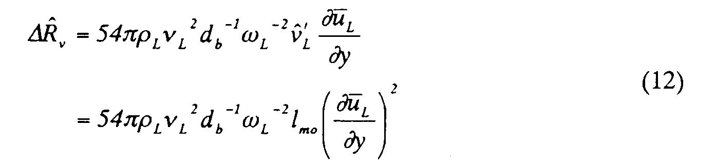
- Substituting equation (11) in equation (6) and denoting the density of liquid by ρL , and using a known relationship µ L =ρ L ν L between viscosity coefficient ν L and ρ L , squared average value of resistive force ΔR ν is given by equation (12):where lmo is the mixing length corresponding to the mean free path of a near-wall bubble. Strictly speaking, however, lmo does not correspond exactly to the mean free path of a bubble, because the apparent mixing length is affected by the amount of decrement in the shear stress caused by the resistive force of the bubble.
- The range of near-wall distance is shown in Figure 2 where the diameter of a bubble db defines the extent of this distance from the wall, and the representative distance is taken at y=db /2.
- The magnitude of the gas mixing length lmo in the near-wall region is given by equation (13).
- Substituting y=db /2 in equation (13), equation (14) is obtained.

- In the meantime, the turbulence cycle 2π/ω L can be assumed to be equal to the time duration T *L (integral time scale) required for a vortex to pass through a given point, so that equation (15) can be established.
- Therefore, squared average of the resistive force ΔR ν is obtained by substituting equations (14) and (15) in equation (12) to derive equation (16).
- An average length for one bubble in its spatial element (that is, an average length of free movement for one bubble on the wall surface) can be expressed as (π/6α w )1/2 db for a given void fraction α w so that the shear stress decrement τ t caused by the resistive force of the bubble is expressed as in equation (17).
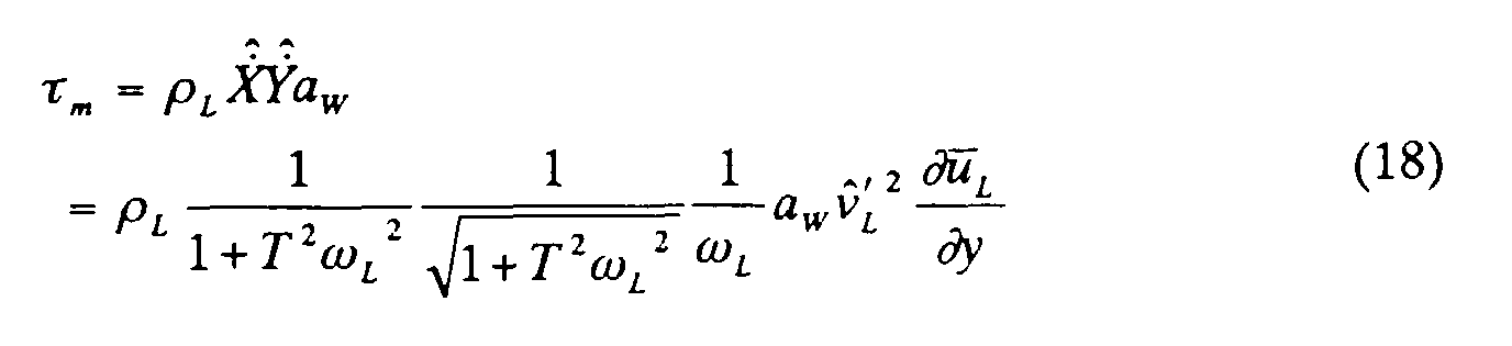
- Here, the shear stress should include an increment factor, as well as a decrement factor, caused by kinetic mass exchange taking place between the water and the bubble. It can be considered that when a bubble moves in the fluid, water of the equal volume flows into the space vacated by the bubble. Therefore, the movement of a bubble in the turbulent boundary layer can be considered to be equivalent to an added movement of water of the same volume. The mechanism of additional stress generation is the same as the Reynolds stress generated by the movement of liquid particles, therefore, shear stress increment τ m cab be expressed as in equation (18).
- In the high frequency band region defined by equation (10), the increment τ m is given by equation (19).
- Comparing the shear stress increment τ m given by equation (19) and the shear stress decrement τ t given by equation (17), in the case of the high frequency band region defined by equation (10), it can be seen the term 1/TωL in the increment τ m is higher than a third-order effect compared with the decrement τ t . When the terms higher than the first-order are neglected, the increment τ m can be ignored. Therefore, regarding the effects of the shear stress in the high frequency band region, it can be understood that the decrement effect is more predominant than the increment effect.
- Here, if a change in the shear stress τw in a bubbly flow field is considered to be caused by the mixing length decrement lmb in the gas mixing length lm due to the presence of the bubble, the shear stress τ w on the wall surface can be expressed by equation (20).where µ m is an apparent viscosity coefficient (a coefficient in molecular viscosity term).

- Because the vortex viscosity element (Reynolds stress) in the second term is larger than the molecular viscosity element in the first term in the turbulent flow region, the shear stress τ w on the wall surface can be expressed as in equation (21).where τ W0 is the characteristic Reynolds stress for the liquid phase. Shear stress decrement τ t , caused by the differential velocity between gas/liquid phases is given by the following equation (22).

- Comparing equation (22) with equation (17), it can be seen that the mixing length change lmb is given by equation (23).

- Dimensionally, the product of integral time-scale T * L (time term) and the squared average of the turbulent velocity (length/time) expresses a 1/2 of the mean free path of the bubble (length term), and therefore, this quantity may be considered to be proportional to the gas mixing length lm . Particularly, in a region obeying the logarithmic law, equation (24) can be established to lead to equation (25).where b is a constant of proportionality and the term inside the bracket νL /U τ relates to the length (wall variable) of the viscous bottom layer.

- Substituting equation (25) in equation (23), the mixing length change lmb is expressed as in equation (26).
- Grouping all the proportionality constants in equation (26) in an empirical constant a given by equation(28), equation (26) can be re-expressed as in equation (27).
- It can be understood from equation (27) that the effects of a bubble can be expressed by revising the normal wall constant κ for non-bubbly flow. Parametric variables are summarized in the following equations (29)∼(32).
- Logarithmic law can still be applied, and these expressions are consistent with the premises of equation (25). In other words, a revised wall constant κ2 for bubbly flow can be expressed as in equation (33).
- Therefore, the operative wall constant κ1 for bubbly now can be expressed by subtracting the revised wall constant κ2 from the normal wall constant κ for non-bubbly flow (i.e., single phase) according to equation (34).

- Equation (34) has an extremely interesting structure. Control parameters for turbulent flow are contained inside the bracket, and are expressed by a ratio of the size of viscous sublayer and the size of the bubble (denominator db /a is proportional to the bubble diameter). From equation (25), it can be seen that the extent of turbulent flow is deeply related to the extent of viscous sublayer, and therefore, the analytical model in the present embodiment suggests that the numerical simulation should be based on the ratio of the bubble size and the extent of the turbulent flow field. Looking only at this result, the present model is not inconsistent with past experimental observations that turbulence control is achieved when the bubble size is small relative to the extent of turbulent flow field.
- In the low frequency band region, the shear stress decrement τ t caused by the bubble, given in equation (17), is of the order of (Tω L )2 and is very small. Therefore, the shear stress τ W is given by adding the increment τ m to the shear stress τ W0 for non-bubbly flow to yield an equation (35).

- An approximate solution in the high frequency band region, where a decrease in the shear stress plays the dominant role as explained above, can be represented by the skin-friction ratio Cf/Cf0 , and a method of computing this ratio will be presented in the following. Although the solution is approximate, it has an advantage that logarithmic solutions can avoid a need for complex function expressions. Subscript "0" refers to the non-bubbly flow field, that is, a single phase flow field.
- In a flow field without a bubble whose velocity distribution is logarithmic, the following equations (36)∼(39) can be established.

- When a bubble is present, the following equations (40)∼(43) can be established in correspondence to equations (36)∼(39) by using the operative wall constant κ1.

- The reason for assuming that B is constant in both flow fields, with or without the bubble on the wall, is based on the reported experimental observation (Iwashina Chiaki, Tokyo University, Faculty of Engineering, Marine Engineering Department, Graduate Thesis "Mechanisms for turbulent-friction reduction using micro-bubbles", 1998) that there is no change in the pattern of turbulent flow near the wall (log y+→0). It was interpreted that this phenomenon indicates that B is constant.
- If the position variable y is assumed to be equal to the thickness δ of the turbulent boundary layer (turbulent boundary layer thickness δ is the same regardless of the presence or absence of the bubble), equations (36) and (40) above can be re-written as equations (44), (45).
- In the meantime, local friction factor Cf0 in non-bubbly flow and the same in bubbly flow Cf are expressed, respectively, by equations (46) and (47).
- At this time, by subtracting equation (44) from equation (45), equation (48) is obtained.

- The term (Cf/Cf0 )1/2 in equation (48) is expanded about 1, and taking the first-order terms, the following equation (49) is obtained.

- Further, expanding the viscous sublayer term ν L /Uτ in the operative wall constant κ1 for bubbly flow, the following equation (50) is obtained.
- Equation (50) is substituted in equation (33) to obtain κ2, which is substituted in equation (34) to obtain κ1, and the κ1 so obtained is substituted in equation (49) to solve for the skin-friction ratio Cf/Cf0 to produce the following equation (51).In equation (51), κ10, κ20, δ0 + are respectively given by equations (52)∼(54) given below. It is to be noted that bubbly flow of micro-bubbles is different from a suspension of dispersed fine particles in terms of the conditions related to the diameter of the bubble, and therefore, as a first zero-order approximation, it is assumed that ν L = ν where νL relates to the single liquid phase and ν relates to a two-phase mixture of liquid and bubble.


- Further, in normalizing the shear force on the wall surface to a non-dimensional quantity with a common ρU2 /2, the skin-friction ratio Cf/Cf0 given in equation (51) can be expressed as in equation (55).

- Next, equation (55) was evaluated using a forty meter model ship (40-m model ship) to produce data that will be examined in detail below. The empirical constant a used in equation (27) was determined using the experimental data obtained by Guin et al. (1996).
- The turbulent boundary layer in the stern-side of the 40-m model ship has a thickness of several hundred mm, which is sufficiently greater than the diameter of the bubbles of about 2 mm, and the float effect of the bubble is greater than the dispersion effect caused by turbulence. Therefore, the amount of bubbles congregating near the wall surface can be estimated roughly from the main fluid velocity and the air flow rate.
- Near-wall void fraction of the 40-m model ship was considered as follows. The center velocity of a small-scale vortex generated by bubble ejection is assumed to be a half of the main fluid velocity, i.e., 0.5U (refer to Kobayashi, 1983), and applying the 1/7 multiplier rule, the position of the center of the small-scale vortex is about 0.1δ from the surface of the wall. The end of the vortex is twice this value, i.e., 0.2δ, and therefore, it may be considered that the region most relevant in generating turbulent flow stress is located between 0.1δ-0.2δ from the wall surface.
- Based on such a consideration, the values of average void fraction α w existing in the range between the wall surface and a depth of 0.2δ were used in the analyses. Values of the parameters for non-bubbly flow were obtained using the 1/7 multiplier rule, and the empirical constant a was chosen to be 20 so as to conform to the experimental data of Guin (1996) as shown in Figure 3.
- Verification results are shown in Figures 4-7. Using the model ship velocity as a parameter, experimental results of skin-friction ratio Cf/Cf0 and theoretical results of Cf/Cf0 obtained from equation (55) are compared in Figure 4, when the bubbles are jetted from the bow of the model ship. Similarly, Figure 5 compares the same when the bubbles are jetted from the center of the bottom surface. Similarly, Figure 6 compares the same when the bubbles are jetted from the bow as well as from the center of the bottom surface. Figure 7 compares the cases of using the flow rate of air ejected into water as a parameter, when the bubbles are jetted from the bow.
- In this embodiment, equation (55) for evaluating the effects of skin-friction reduction was developed by re-examining more rigorously some of the variables which were not fully examined in the technique used in our previous work.
- In deriving equation (55) by comparing the magnitudes of the time-constant of a bubble and the turbulence cycle in the turbulent boundary layer, three regions were identified: a low frequency band region where Tω L << 1, a middle frequency band region where Tω L = O (1) and a high frequency band region where Tω L >> 1. In this investigation, an approximate solution was developed for the high frequency band region. In the high frequency band region, it shows that, for a given value of [sublayer size]/[bubble size] , skin-friction ratio Cf/Cf0 produce a monotonic decrease to indicate that the bubbles exert a large influence.
- Also, in the high frequency band region, shear stress increment τ m is small relative to the shear stress decrement τ t . However, in the middle frequency band region, the increment τ m cannot be ignored and, contrastingly, in the low frequency band region, the effect of the shear stress increment becomes predominant. In other words, in the high frequency band region, response of the bubble movement is poor and the movement is small so that there is little kinetic mass exchange, and the effects of resistive force of the bubbles on the shear stress reduction become high. In contrast, in the low frequency band region, there is high activity in kinetic mass exchange, and the effect of shear stress increase becomes high. Figure 8 shows a conceptual summary of the tendency of the skin-friction ratio, Cf/Cf0 in the three frequency regions.
- As demonstrated in Figures 4∼7, the analytical solution for Cf/Cf0 presented in this embodiment agrees qualitatively with experimental data. Especially, prediction on the bubbly flow retaining distance has been greatly increased. Also, it appears that the agreement is improved as the model ship speed is increased, and it is thought that this is caused by the fact that assumptions reflect the conditions in the high frequency band region. The future topics include development of analytical solutions for all frequency band regions and numerical computations.
- Next, the second embodiment of the invention will be explained.
- In the First Embodiment, the solution for the skin-friction ratio Cf/Cf0 was developed as in equation (55), by assuming that the operative wall constant κ1 for bubbly flow was obtained by subtracting the revised wall constant κ2 from the normal wall constant κ for non-bubbly flow as in equation (34).
- However, other parametric input terms, such as near-wall void fraction α W and the bubble diameter db were not examined in sufficient detail. There are various measured data on bubble diameters, and one aspect of the difficulty is to unilaterally decide the bubble size to be used in the analysis.
- In the second embodiment, simultaneous equations involving equation (34) and a governing equation for void fraction were established so that the terms for bubble diameter db and the empirical constant a can be eliminated such that, in the newly developed equation for skin-friction reduction, bubble size was replaced by void fraction as an input parameter.
- In the following explanation, it was considered that a linear pattern of void fraction distribution is the most stable in order to satisfy the following stability conditions for solving the simultaneous equations:
- A. the governing equation for void distribution does not diverge; and
- B. the sum of the kinetic energy of bubbly flow (with consideration for suppressing the turbulent flow) and potential float energy of bubbly flow should be minimized.
-
- Within such a framework, two types of fluid flow effects on bubbly flow were considered: one-way coupling approach which considers fluid flow affecting the movement of bubbles; and two-way coupling approach which considers fluid flow effects on the bubble movement as well as bubble movement effects on the fluid flow.
- Basic assumptions and methodology were adopted from a 43rd publication of the JSPC (Joint Ship Propulsion Committee, 1997), and the governing factors for dispersion of bubbles were attributed to turbulence and float force, for simplicity. It was considered that bubbly flow velocity was determined in all cases by resistive forces. In the Stokes equations, force is proportional to velocity so that it is not necessary to establish kinetic equations, for describing the movement of bubbles on the basis of interacting forces, and that total velocity can be expressed by superposition of velocity expressions for various driving factors. Bubbles are treated as dispersing particles forming a continuous string of particles, that is, behave as a gas phase.
- Figure 9 shows a model for analyzing the movement of bubbles. An examination region bounded by points A, B, C and D is designated within the turbulent boundary layer, and is surrounded by four dispersing particles (1)-(4). The center of each bubble represents the center of movement of each bubble, and the dotted line represents a circular boundary of free movement of each bubble, and each diameter representing a respective mean free path. The distance between the centers is assumed to be equal to the mean free path.
- Here, a term equivalent to the mean free path in the two-dimensional theory of turbulent boundary layer is the mixing length, therefore, as a first-order approximation, the distance between the centers may be expressed as clb in terms of the mixing length lb of the gas phase and an empirical constant c. Physically, the constant c relates to a dispersion coefficient. Also, the distance between the centers relates to a distance between the neighboring vortexes, and can be interpreted as a measure of the vortex length.
- Designating a flow flux in x-direction from boundary AB to boundary CD as jx , and a flow flux in y-direction from boundary AD to boundary BC as jy , the following relation can be derived from the law of conservation of mass.
- When a gas phase having a void fraction a disperses in the liquid phase, and travels while under the influence of a resistive force caused by the average fluid velocity and a float force, the flow fluxes jx , jy can be approximated by the following expressions, respectively.and

- The second term in equation (57) relates to a flow flux induced by the turbulent velocities of bubble (2) and bubble (4) shown in Figure 9. Also, the third term in equation (58) relates to a flow flux induced by the turbulent velocities of bubble (1) and bubble (3).
- At this time, premises indicated in equations (59)∼(61) are selected. These conditions are set to zero, meaning that substitution of equations (57), (58) in equation (56) produce results which can be neglected in comparison with other terms. The order of magnitude was judged on the basis of the 1/7 multiplier rule. In these equations, Re stands for Reynolds number.


- Under these conditions, equations (57), (58) are substituted in equation (56) to obtain equation (62).

- Considering that the flow flux in y-direction is zero at the wall surface, the following equation (63) is established.
- Expanding equation (63) leads to equation (64). In this embodiment, equation (64) is designated as the governing equation for void fraction distribution.

- In equation (64), first and second terms relate to flow fluxes expressing dispersion caused by turbulence. Of the two, the first term is considered to be related to liquid-controlled dispersion caused by the liquid turbulence while the second term is considered to be related to void-controlled dispersion.
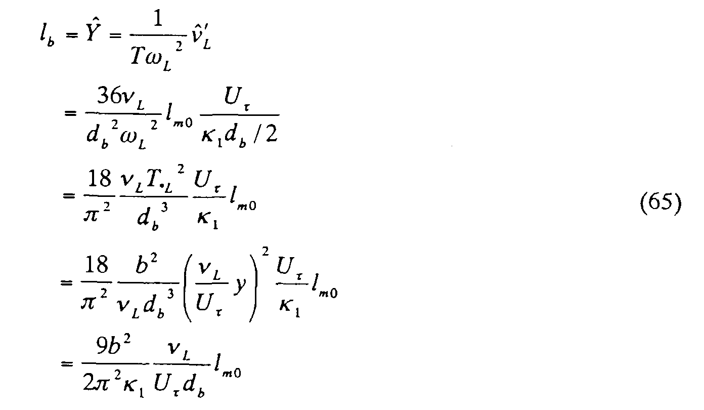
- To obtain a gas phase mixing length lb , it is necessary to examine again the kinetic equation based on movement of the bubbles. In the near-wall region where the velocity distribution in a flow field obeys the logarithmic law, the relation between the gas phase mixing length lb and the actual (not apparent) liquid phase mixing length lm0 is derived as shown in equations (65) and (66).and
 and
and
- Before obtaining an expression for void fraction distribution, liquid phase mixing length lm0 is defined as follows, for convenience.
- In the region where the velocity distribution in a flow field obeys the logarithmic law, the equations (70) and (71) are established.
- Obtaining the gas phase mixing length lb from equations (66) and (69), and substituting the resulting lb together with equations (70), (71) in the governing equation (64) for void fraction, equation (72) is obtained.where κ0 is a constant.

- In this case, if it is assumed that a local void fraction α is a function only of the position parameter y, equation (72) can be rewritten as follows.

- Equation (73) is a separable-variable differential equation, and a solution can be derived readily as follows.

- These constants K 0 and K 1 are parameters for determining the void fraction distribution, where K 0 specifies the peak position and K 1 specifies the overall size of the void fraction.
- Figure 10 is a graph showing how the local void fraction α in y-direction varies when the constant K 0 is altered. Case 1 illustrates a local void distribution when K 0<1; Case 2 when K 0=1; and Case 3 when K 0>1.
- In Case 1, the local void fraction α diverges at the wall surface (y=0). In Case 2, divergence does not occur, and the local void fraction a is maximum at the hull surface. In Case 2, due to changes in the operative wall constant κ1, the turbulence appears to be most suppressed and the kinetic energy is minimized, and comparing with Case 3, float potential energy is minimized. Therefore, it can be considered that Case 2 represents the most stable void fraction distribution.
- As shown by equation (75), the parameter K 0 varies as the 4th power of the bubble diameter, so that the local void fraction α is very sensitive to changes in the bubble dimension. Considering that the empirical constant a also exerts a large influence on the parameter K 0 it is extremely difficult to unilaterally select a bubble size, which varies widely in reality, and to input some bubble diameter db as a variable to estimate the void fraction distribution.
- For these reasons, the approach taken in this embodiment is to adjust the parameters K 0, K 1 in the void fraction distribution equation (74) until the computed a matches with the actual void fraction distribution, and the value of K 0 so obtained is used in equation (75) to derive a value of (db /a). Simultaneous equations are then established with equation (34) to develop an expression for skin-friction ratio Cf/Cf0 by two-way coupling approach.
- Also, in equation (75), an expression for one-way coupling can be conveniently developed by replacing the bubbly flow frictional velocity U τ with the non-bubbly flow U τ 0 , and replacing the constant κ1 for bubbly flow with κ for non-bubbly flow.
- Figure 11 is a block diagram of the computational steps for one-way coupling and two-way coupling approaches. These expressions, one-way coupling and two-way coupling, are used in describing Lagrangian models, but they are useful also in describing the present computational models. One-way coupling approach is a method to perform computations related to bubbly fluid flow based on computed results related to bubbles, and two-way coupling approach is a method to perform computations related to bubbly fluid flow based on computed results related to bubbles, and feed back the results related to bubbly fluid flow to perform computations related to bubbles.
- In this section, the aspects of the model examined are determination of empirical constant c, evaluation of the method for approximation and the qualitative expressive ability of the model.
- Examination of the experimental results (refer to Guin et al. 1996) for a two-dimensional channel (plate on top) reveals that the void fraction is close to zero in the middle of the channel and increases towards the wall in a linear manner (refer to Figure 12), when the fluid flow velocity is close to practical ship speed, U=5∼8 m/s, and the void fraction is less than 7%. Such a void distribution pattern is similar to Case 2 mentioned above. If the estimation precision can be maintained by limiting the distribution pattern to Case 2, it would be useful in practical situations even though the applicability range may be narrowed.
- Therefore, examination process was carried out not only for two-way coupling approach and computations using near-wall void fraction data, but also for the case of convenient approximation based on one-way coupling approach and an assumption of linear distribution of void fraction (Case 2: K 0=1). As described later, trial computations were performed using the two-dimensional experimental data of Guin et al. on a 40-m model ship. Also, similar to the first embodiment, near-wall void fraction α w was assumed to be the average void fraction existing within the distance of 0.2δ from the wall surface.
- Figure 13 shows the results in terms of the effects of average void fraction α m (based on the total width of the channel) on the skin-friction ratio Cf/Cf0 encountered in the fluid flowing within the channel. Equations (75), (76) were used to obtain void fractions which would duplicate the near-wall void fraction measured by Guin et al. The computed results using the two-way coupling approach (triangles) and those obtained using the one-way coupling approach (squares) are also shown in Figure 13. For reference purposes, results obtained by Madavan (1984) are also plotted in Figure 13.
- In the two-way coupling approach, measured values of void fraction were input for the purpose of verifying the properties particular to the shear stress model. The trend seems to agree qualitatively in general. However, when the average void fraction α m begins to exceed 0.05, significant quantitative difference begins to be observed. This is considered to be caused primarily by the fact that the skin-friction ratio Cf/Cf0 obtained by Guin et al. is normalized by the main fluid velocity in non-bubbly flow Um0 while, for convenience, the present values of Cf are normalized by the main fluid velocity in bubbly flow and those for Cf0 are normalized by the main fluid velocity in non-bubbly flow, and therefore, the results do not agree quantitatively, particularly when the flow path is narrow.
- For the case of narrow flow path, it remains as a topic of future study to estimate the main fluid velocity for bubbly flow accurately by computation. It should be noted that the water tank used by Madavan, measuring 508 × 714 mm in cross section, is relatively large so that the influence of using a different normalization standard is relatively small. Also, the wall-surface void fraction is based on measured absolute values so that if there is an error in the absolute value of void fraction, computation results are affected directly by the magnitude of the error.
- In the one-way coupling approach, the purpose is to examine the extent of applicability of the convenient methodology. Agreement is observed up to about 0.05 in the average void fraction α m . In the experiments using the 40-m model ship described later, maximum value of average void fraction α m , is obtained when the fluid velocity is 7 m/s, air jet flow rate is 300 l/min ejected at a distance x=3m, which is the location of the sensor closest to the bow of the ship. Average void fraction observed under these conditions was 0.06 (relative to the thickness of the boundary layer).
- Overall, average void fraction is much lower, and it is considered that the accuracy of estimation can be maintained even with the simplified approach of one-way coupling method. In this case, the near-wall void fraction α w can be obtained using turbulent layer average void fraction α a ν according to equation (77).
- Empirical constant c was assumed to be 0.01. All subsequent computations are based on this value.
- Computations for the 40-m model ship were performed by one-way coupling approach according to Case 2 in which the void fraction distribution is assumed to vary linearly.
- Figures 14∼17 are graphs showing computed and measured results. Figure 14 shows the effects of the distance from the origin of bubble jet on the skin-friction ratio Cf/Cf0 for various ship speed values, when the bubbles are ejected from the nozzles on the bow-bottom of the ship. Figure 15 shows the same when the bubbles are ejected from the nozzles in the middle of the ship. Figure 16 shows the same when the bubbles are ejected from the nozzles at both the bow and the middle of the ship. Figure 17 shows the effects of the distance from the origin of the bubble jet on the skin-friction ratio Cf/Cf0 for various flow rates of gas jetting from the nozzles in the bow of the ship.
- From Figure 14, it can be seen that quantitative agreement between computation and observation is better at a fluid velocity of 5 m/s than at 7 m/s. This may be because the assumption of high frequency band is not appropriate for the flow fields in the range of 5∼6 m/s. Analysis of frequency effects remains as a future topic.
- The reason for the disagreement when the bubbles are ejected from the middle of the ship may be because, immediately after ejection, near-wall void fraction increases temporarily due to the initial kinetic influence of the bubbles. The agreement improves towards downstream because the kinetic influence becomes less as the bubbles travel in the turbulent layer. Figure 17 indicates that the effects of jet gas flow rate is well represented by the analytical model.
-
- (1) By solving simultaneous equations of a turbulent flow model and a governing equation for void fraction distribution, a methodology has been developed for computing a skin-friction ratio Cf/Cf0 by inputting a void fraction distribution pattern instead of the bubble diameter db . Also, the empirical constant a is eliminated in the process of solving the simultaneous equations.
- (2) It was found that the quantitative expressions for approximation solution in the high frequency band region (turbulent flow model), with consideration for void fraction distribution, produced excellent results.
- (3) Although the range of applicability becomes limited, estimation is possible even if a linear pattern is adopted for the void fraction distribution. When the main fluid velocity is in the range of 5∼8 m/s and the average void fraction in the turbulent layer α av is less than 0.05, the trend of skin-friction reduction can be estimated even if the void fraction distribution is approximated to be linear. In this case, estimation accuracy is maintained even with the one-way coupling approach.
-
- Assumption of linearity of void fraction distribution pattern at low fluid velocity and low jet volume was made on the basis of experimental observations, and theoretically, this condition was achieved by providing stability conditions of non-divergence and energy minimization. Detailed mechanistic interpretation remains as a future topic, however.
- Other reasons for disagreement may exist also. For example, there is possibility that, when external perturbation due to turbulent flow is small and the volumetric force is acting towards the interior of the ship, a stability condition may mean that the closer the bubble is to the wall the larger the bubble volume. It may also be that an apparent viscosity of the fluid changes as a result of mixing with the bubbles so that bubbly flow may be a phenomenon similar to spreading of an adhered high-viscosity fluid mass over the ship wall surface. Or, bubbly flow dynamics involves an ever-changing process of mixing of bubbles of various sizes in search of transient stability by collapsing and coalescing, leading to macroscopic adjustments in bubble sizes to achieve an ultimate dynamic equilibrium between void dispersion force and float force.
- However, theoretically, void fraction distribution pattern is dependent on the 4th power of bubble diameter, so that macroscopic adjustment in bubble size occurs at a very small scale. At this stage of the model development, further discussion of microscopic analysis of bubbly fields comprised of various sizes of bubbles would be fruitless, and it remains as a large future topic.
- Salient features of the method of the present invention are summarized in the following.
- (1) In a high frequency band region, the method enables more accurate analysis of the effects of bubbly flow in reducing the skin-friction.
- (2) The method enables to eliminate the bubble size db from the operative wall constant κ1 in the wall law for bubbly flow, by using actual void fraction distribution to develop a governing equation for void fraction distribution. Because db is difficult to determine unilaterally from various experimental results and db has such a large effect on any analytical solution for the skin-friction ratio Cf/Cf0 , eliminating the bubble size as an input parameter contributes significantly to the ability of the model to estimate the skin-friction ratio Cf/Cf0 accurately.
- (3) According to conventional theoretical approaches, friction reduction effects can be analyzed only for a plate configuration (bottom hull), but the development of equations in the direction at right angles to the ship surface (normal direction) enables the effects of bubbles acting on a slanted hull surface to be analyzed.
-
Claims (6)
- A method for analyzing effects of generating bubble jets in a flow field near a ship surface on reducing skin-friction in a cruising ship comprising the steps of:obtaining a shear stress decrement τ t , produced by having a bubble in said flow field in terms of a resistive force ΔR ν acting on said bubble, derived from movements of said bubble in a fluid flow direction, x-direction, along said cruising ship as well as in a direction at right angles to a ship wall surface, y-direction, in accordance with a definition of a high frequency band region in which a product of a bubble time-constant T and a turbulence frequency ω L in said flow field is greater than 1;obtaining an operative wall constant κ1 in the wall law when there is a bubble having a parametric bubble diameter db , by assuming that said shear stress decrement is generated by a decrease in a mixing length; andobtaining a solution for skin-friction ratio, Cf/Cf0 , in said high frequency band region, according to an expression relating said operative wall constant κ1 to a local friction factor Cf for bubbly flow, and an expression relating a normal wall constant κ in the wall law in non-bubbly flow to a local friction factor Cf0 in non-bubbly flow.
- A method according to claim 1, wherein said bubble diameter db is eliminated as a parameter from said operative wall constant κ1 in said wall law for bubbly flow, by specifying a governing equation for a void fraction distribution using an actual pattern of bubble distribution.
- A method according to claim 2, wherein said governing equation for void fraction distribution is specified under stability conditions: to produce non-divergence in said governing equation; and to minimize a sum of the kinetic energy of bubbly flow, with consideration for suppressing the turbulent flow, and a potential float energy of bubbly flow.
- A method for analyzing effects of generating bubble jets in a flow field near a ship surface on reducing skin-friction in a cruising ship comprising the steps of:wherein equations referenced above are listed as follows;performing a Fourier transform on kinetic equations (1) and (2) for a bubble moving in x- and y-directions, representing a fluid flow direction and a direction at right angles to said ship surface, respectively, in terms of an added mass of a bubble mA , a bubble diameter db , a dynamic liquid viscosity coefficient ν L , and obtaining an expression for a gain in x-direction Gx and an expression for a gain in y-direction Gy comprised of a bubble time-constant T and a turbulence frequency ωL , based on equations (3) and (4) respectively;obtaining from equation (16) a resistive force ΔRν acting on a bubble in a high frequency band region where a product of a bubble time-constant T and a turbulence frequency ω L is greater than 1, in terms of a normal wall constant κ in the wall law in non-bubbly flow, a fluid density ρL , a dynamic fluid viscosity coefficient ν L , and a time-averaged velocity in x-direction uL , by assuming that a turbulence cycle 2π/ω L in said flow field is equal to said integral time-scale T * L ;obtaining a shear stress decrement τ t caused by said resistive force ΔRν from equation (17);obtaining a mixing length decrement lmb from equation (27) in terms of an empirical constant a, said bubble diameter db , said dynamic viscosity coefficient ν L , a frictional velocity Ut and a near-wall local void fraction α W , by comparing said equation (17) with equation (22) which expresses a shear stress decrement τ t that is assumed to be produced by a mixing length decrement lmb ;obtaining a revising wall constant κ2 in the wall law as in equation (33) by using said equation (27), and obtaining an expression as in equation (34) for an operative wall constant κ1 for bubbly flow, in terms of said empirical constant a and said bubble diameter db as parameters, by subtracting said revised wall constant κ2 from said normal wall constant κ,deriving equation (44) relating said normal wall constant κ to a local friction factor Cf0 in non-bubbly flow, and equation (45) relating said operative wall constant κ1 to a local friction factor Cf in bubbly flow, according to equation (36) for non-bubbly flow velocity and equation (40) for bubbly flow velocity, assuming that a fluid velocity distribution obeys a logarithmic law and that a position parameter y is represented by a turbulent boundary layer thickness δ;subtracting said equation (44) from said equation (45) to obtain equation (48), and expanding a series expression (Cf/Cf0 )1/2 in equation (48) about 1 so as to derive equation (49) comprised of first-order expansion terms while also expanding a bottom-layer term ν L/Ut in said equation (48) for an operative wall constant κ1 for bubbly flow, thereby deriving equation (50); andobtaining an analytical solution (55) for a skin-friction ratio Cf/Cf0 in said high frequency band region by substituting said equation (50) in said equation (33) to yield a first result and substituting said first result into said equation (34) to yield a second result and substituting said second result into said equation (49) and solving to obtain an expression for said analytical solution;







- A method according to claim 4, wherein said bubble is considered to obey a law of conservation of mass expressed in equation (56) while moving in a tlow field near said ship surface that includes a fluid flow flux jx in a fluid flow direction, x-direction, and a fluid flow flux jy at right angles to said ship surface, y-direction, as a result of dispersion of a gas phase having a local void fraction a, under an influence of a resistive force acting on said bubble caused by an average fluid velocity and a float force of said bubble;approximating said jx in terms of a local void fraction a, an average fluid velocity in x-direction uL, a squared average value of gas phase velocity in y-direction ν b , an empirical constant c, a gas phase mixing length lb as in equation (57), and approximating said jy in terms of said local void fraction a, an average fluid velocity in y-direction νL, a bubble ascending velocity qg , said empirical constant c, said gas phase mixing length lb as in equation (58) so as to derive an expression for a governing equation for a void fraction distribution as in equation (64);solving said governing equation (64) to obtain an expression (74) for said local void fraction α in terms of parametric constants K 0 and K 1 and turbulent layer thickness δ;determining a value for K 0 from an experimentally-obtained void fraction distribution pattern, and substituting said value of K 0 in an expression for K 0 in equation (75) to form simultaneous equations with said equation (34), thereby replacing said operative wall constant K 1 for bubbly flow with a bubble diameter db and an empirical constant a, and deriving an analytical expression for skin-fraction ratio Cf /Cf0 based on a void fraction distribution as a parameter, wherein equations reference above listed below.



- A method according to claim 5, wherein said constant K 0 is determined from said experimentally-obtained void fraction distribution pattern under stability conditions: to produce non-divergence in said governing equation; and to minimize a sum of the kinetic energy of bubbly flow, with consideration for suppressing the turbulent flow, and potential float energy of bubbly flow.
Applications Claiming Priority (2)
| Application Number | Priority Date | Filing Date | Title |
|---|---|---|---|
| JP10155044A JPH11342889A (en) | 1998-06-03 | 1998-06-03 | Analysis Method for Friction Drag Reduction Effect of Bubbles on Ship |
| JP15504498 | 1998-06-03 |
Publications (2)
| Publication Number | Publication Date |
|---|---|
| EP0962383A2 true EP0962383A2 (en) | 1999-12-08 |
| EP0962383A3 EP0962383A3 (en) | 2001-11-21 |
Family
ID=15597454
Family Applications (1)
| Application Number | Title | Priority Date | Filing Date |
|---|---|---|---|
| EP99401281A Withdrawn EP0962383A3 (en) | 1998-06-03 | 1999-05-28 | Method for analyzing friction reduction effects of bubbles in a ship |
Country Status (7)
| Country | Link |
|---|---|
| US (1) | US6324480B1 (en) |
| EP (1) | EP0962383A3 (en) |
| JP (1) | JPH11342889A (en) |
| KR (1) | KR100309601B1 (en) |
| CN (1) | CN1244634A (en) |
| FI (1) | FI991259A7 (en) |
| TW (1) | TW392043B (en) |
Families Citing this family (14)
| Publication number | Priority date | Publication date | Assignee | Title |
|---|---|---|---|---|
| US6408679B1 (en) * | 2000-02-04 | 2002-06-25 | The United States Of America As Represented By The Administrator Of The National Aeronautics And Space Administration | Bubble measuring instrument and method |
| JP2006172136A (en) * | 2004-12-15 | 2006-06-29 | Canon Inc | Information processing apparatus and information processing method |
| US8327784B2 (en) | 2009-03-23 | 2012-12-11 | Dan Nicolaus Costas | Apparatus for generating and distributing compressed air for reducing drag |
| US7997221B2 (en) * | 2009-03-23 | 2011-08-16 | Dan Nicolaus Costas | Apparatus for reducing drag on a nautical vessel |
| US8763547B2 (en) | 2012-07-25 | 2014-07-01 | Dan Nicolaus Costas | Apparatus for lowering drag on a moving nautical vessel |
| JP2017507072A (en) * | 2014-03-05 | 2017-03-16 | シルバーストリーム・テクノロジーズ・ビー.ブイ. | Use of an air lubrication system to reduce marine product adhesion on board. |
| JP6482888B2 (en) | 2015-02-05 | 2019-03-13 | 中国塗料株式会社 | Method of predicting frictional resistance of rough surface and surface performance evaluation apparatus |
| JP5931268B1 (en) * | 2015-12-07 | 2016-06-08 | 有限会社ランドエンジニアリング | Estimating the frictional resistance reduction for the entire ship |
| CN106114750B (en) * | 2016-08-25 | 2018-05-15 | 武汉理工大学 | Based on bubble drag-reduction and M ship types compound intelligence control system and control method |
| CN107933951B (en) * | 2017-11-13 | 2020-07-14 | 北京临近空间飞行器系统工程研究所 | A method for discriminating the flow state in flight test based on the variation law of frictional resistance |
| CN109190237B (en) * | 2018-08-28 | 2023-04-07 | 中国舰船研究设计中心 | Method for calculating numerical value of multi-source concurrency and flow of ship bubbles |
| CN110296912B (en) * | 2019-06-19 | 2020-07-21 | 北京理工大学 | Ultrasonic-based detection system and method for dynamic turbulent kinetic energy of dust cloud diffusion |
| KR102669185B1 (en) | 2022-04-11 | 2024-05-27 | 한국해양과학기술원 | Frictional drag test apparatus installed in cavitation tunnel |
| CN116176789A (en) * | 2022-12-07 | 2023-05-30 | 大连船舶重工集团有限公司 | A verification test method for real ship speed and energy efficiency of air layer drag reduction system |
Citations (4)
| Publication number | Priority date | Publication date | Assignee | Title |
|---|---|---|---|---|
| JPH08144646A (en) | 1994-11-17 | 1996-06-04 | Tetsuya Inaba | Sliding door frame for building |
| JPH09142818A (en) | 1995-09-22 | 1997-06-03 | Mitsubishi Chem Corp | Carbon black molded body |
| JPH09292999A (en) | 1996-04-26 | 1997-11-11 | Nec Corp | Transaction exclusive system in cluster system |
| JPH1055453A (en) | 1996-03-21 | 1998-02-24 | Samsung Electron Co Ltd | Multiprocessor graphics system |
Family Cites Families (6)
| Publication number | Priority date | Publication date | Assignee | Title |
|---|---|---|---|---|
| US5054412A (en) * | 1989-10-31 | 1991-10-08 | The United States Of America As Represented By The Administrator Of The National Aeronautics And Space Administration | Hydrodynamic skin-friction reduction |
| WO1994026583A1 (en) * | 1993-05-11 | 1994-11-24 | Ishikawajima-Harima Heavy Industries Co., Ltd. | Method of reducing friction on cruising body, cruising body with reduced friction, method of and apparatus for generating microbubbles for use in reduction of friction |
| US5613456A (en) * | 1995-07-28 | 1997-03-25 | The United States Of America As Represented By The Secretary Of The Navy | Microbubble positioning and control system |
| KR19990071792A (en) * | 1995-12-04 | 1999-09-27 | 카토히로하루 | Method of reducing frictional resistance of hull, Method of reducing frictional resistance using this method, and Method of analysis of blowing bubble in ship |
| US5967071A (en) * | 1997-12-02 | 1999-10-19 | Wipper; Daniel J. | Energy efficient system and method for reducing water friction on the hull of a marine vessel |
| US6145459A (en) * | 1997-12-19 | 2000-11-14 | Ishikawajima-Harima Heavy Industries Co., Ltd. | Friction-reducing ship and method for reducing skin friction |
-
1998
- 1998-06-03 JP JP10155044A patent/JPH11342889A/en active Pending
-
1999
- 1999-05-20 TW TW088108312A patent/TW392043B/en not_active IP Right Cessation
- 1999-05-24 US US09/317,326 patent/US6324480B1/en not_active Expired - Fee Related
- 1999-05-28 EP EP99401281A patent/EP0962383A3/en not_active Withdrawn
- 1999-06-01 KR KR1019990019957A patent/KR100309601B1/en not_active Expired - Fee Related
- 1999-06-02 FI FI991259A patent/FI991259A7/en unknown
- 1999-06-03 CN CN99106981A patent/CN1244634A/en active Pending
Patent Citations (4)
| Publication number | Priority date | Publication date | Assignee | Title |
|---|---|---|---|---|
| JPH08144646A (en) | 1994-11-17 | 1996-06-04 | Tetsuya Inaba | Sliding door frame for building |
| JPH09142818A (en) | 1995-09-22 | 1997-06-03 | Mitsubishi Chem Corp | Carbon black molded body |
| JPH1055453A (en) | 1996-03-21 | 1998-02-24 | Samsung Electron Co Ltd | Multiprocessor graphics system |
| JPH09292999A (en) | 1996-04-26 | 1997-11-11 | Nec Corp | Transaction exclusive system in cluster system |
Also Published As
| Publication number | Publication date |
|---|---|
| US6324480B1 (en) | 2001-11-27 |
| EP0962383A3 (en) | 2001-11-21 |
| FI991259A0 (en) | 1999-06-02 |
| TW392043B (en) | 2000-06-01 |
| KR20000005791A (en) | 2000-01-25 |
| KR100309601B1 (en) | 2001-09-26 |
| FI991259A7 (en) | 1999-12-04 |
| CN1244634A (en) | 2000-02-16 |
| JPH11342889A (en) | 1999-12-14 |
Similar Documents
| Publication | Publication Date | Title |
|---|---|---|
| Manga et al. | Buoyancy-driven interactions between two deformable viscous drops | |
| EP0962383A2 (en) | Method for analyzing friction reduction effects of bubbles in a ship | |
| Hussein et al. | Energy balance for turbulent flow around a surface mounted cube placed in a channel | |
| Shikhmurzaev | Moving contact lines in liquid/liquid/solid systems | |
| Brocchini et al. | The dynamics of strong turbulence at free surfaces. Part 2. Free-surface boundary conditions | |
| Arnal et al. | Laminar-turbulent transition prediction in three-dimensional flows | |
| Shikhmurzaev | Dynamic contact angles and flow in vicinity of moving contact line | |
| Wilcox et al. | Streamline curvature effects on turbulent boundary layers | |
| Martinez et al. | Boundary integral analysis of the creeping flow of long bubbles in capillaries | |
| US6026758A (en) | Method for analyzing bubble jet from a ship | |
| Drazer et al. | Tracer dispersion in two-dimensional rough fractures | |
| Heintz et al. | Measurements on the effect of steps on the transition of laminar boundary layers | |
| van Putten et al. | Wet gas over-reading correction for ultrasonic flow meters | |
| Khayat et al. | Influence of inertia, gravity, and substrate topography on the two-dimensional transient coating flow of a thin Newtonian fluid film | |
| Soubiran et al. | Bubble motion in a potential flow within a Venturi | |
| Marvin et al. | Turbulence modeling for unsteady transonic flows | |
| Astolfi et al. | A model for tip vortex roll-up in the near field region of three-dimensional foils and the prediction of cavitation onset | |
| Vella et al. | The impulsive motion of a small cylinder at an interface | |
| Czernuszenko | Drift velocity concept for sediment-laden flows | |
| Sengupta et al. | Instabilities of flows: With and without heat transfer and chemical reaction | |
| Kalkach-Navarro | The mathematical modeling of flow regime transition in bubbly two-phase flows | |
| Severino et al. | A gas phase displacing a liquid with soluble surfactants out of a small conduit: The plane case | |
| Kalagotla et al. | Modeling particle drag in accelerating flows with implications for sbli in piv-a numerical analysis | |
| Stalker | A characteristics approach to swept shock-wave/boundary-layer interactions | |
| Rodi | Mathematical modelling of turbulence in estuaries |
Legal Events
| Date | Code | Title | Description |
|---|---|---|---|
| PUAI | Public reference made under article 153(3) epc to a published international application that has entered the european phase |
Free format text: ORIGINAL CODE: 0009012 |
|
| AK | Designated contracting states |
Kind code of ref document: A2 Designated state(s): AT BE CH CY DE DK ES FI FR GB GR IE IT LI LU MC NL PT SE |
|
| AX | Request for extension of the european patent |
Free format text: AL;LT;LV;MK;RO;SI |
|
| PUAL | Search report despatched |
Free format text: ORIGINAL CODE: 0009013 |
|
| AK | Designated contracting states |
Kind code of ref document: A3 Designated state(s): AT BE CH CY DE DK ES FI FR GB GR IE IT LI LU MC NL PT SE |
|
| AX | Request for extension of the european patent |
Free format text: AL;LT;LV;MK;RO;SI |
|
| RIC1 | Information provided on ipc code assigned before grant |
Free format text: 7B 63B 1/38 A, 7B 63B 9/00 B, 7G 01N 19/06 B, 7G 01N 13/00 B, 7G 01N 15/02 B, 7G 01N 19/02 B |
|
| AKX | Designation fees paid | ||
| REG | Reference to a national code |
Ref country code: DE Ref legal event code: 8566 |
|
| 18D | Application deemed to be withdrawn |
Effective date: 20020522 |