EP0962398B1 - Procédé de fabrication d'une fermeture inviolable et dispositif de soudage par ultrasons - Google Patents
Procédé de fabrication d'une fermeture inviolable et dispositif de soudage par ultrasons Download PDFInfo
- Publication number
- EP0962398B1 EP0962398B1 EP99109076A EP99109076A EP0962398B1 EP 0962398 B1 EP0962398 B1 EP 0962398B1 EP 99109076 A EP99109076 A EP 99109076A EP 99109076 A EP99109076 A EP 99109076A EP 0962398 B1 EP0962398 B1 EP 0962398B1
- Authority
- EP
- European Patent Office
- Prior art keywords
- container
- welding
- food container
- lid
- ultrasonic welding
- Prior art date
- Legal status (The legal status is an assumption and is not a legal conclusion. Google has not performed a legal analysis and makes no representation as to the accuracy of the status listed.)
- Expired - Lifetime
Links
Images


Classifications
-
- B—PERFORMING OPERATIONS; TRANSPORTING
- B29—WORKING OF PLASTICS; WORKING OF SUBSTANCES IN A PLASTIC STATE IN GENERAL
- B29C—SHAPING OR JOINING OF PLASTICS; SHAPING OF MATERIAL IN A PLASTIC STATE, NOT OTHERWISE PROVIDED FOR; AFTER-TREATMENT OF THE SHAPED PRODUCTS, e.g. REPAIRING
- B29C66/00—General aspects of processes or apparatus for joining preformed parts
- B29C66/80—General aspects of machine operations or constructions and parts thereof
- B29C66/81—General aspects of the pressing elements, i.e. the elements applying pressure on the parts to be joined in the area to be joined, e.g. the welding jaws or clamps
- B29C66/814—General aspects of the pressing elements, i.e. the elements applying pressure on the parts to be joined in the area to be joined, e.g. the welding jaws or clamps characterised by the design of the pressing elements, e.g. of the welding jaws or clamps
- B29C66/8141—General aspects of the pressing elements, i.e. the elements applying pressure on the parts to be joined in the area to be joined, e.g. the welding jaws or clamps characterised by the design of the pressing elements, e.g. of the welding jaws or clamps characterised by the surface geometry of the part of the pressing elements, e.g. welding jaws or clamps, coming into contact with the parts to be joined
- B29C66/81433—General aspects of the pressing elements, i.e. the elements applying pressure on the parts to be joined in the area to be joined, e.g. the welding jaws or clamps characterised by the design of the pressing elements, e.g. of the welding jaws or clamps characterised by the surface geometry of the part of the pressing elements, e.g. welding jaws or clamps, coming into contact with the parts to be joined being toothed, i.e. comprising several teeth or pins, or being patterned
-
- B—PERFORMING OPERATIONS; TRANSPORTING
- B29—WORKING OF PLASTICS; WORKING OF SUBSTANCES IN A PLASTIC STATE IN GENERAL
- B29C—SHAPING OR JOINING OF PLASTICS; SHAPING OF MATERIAL IN A PLASTIC STATE, NOT OTHERWISE PROVIDED FOR; AFTER-TREATMENT OF THE SHAPED PRODUCTS, e.g. REPAIRING
- B29C65/00—Joining or sealing of preformed parts, e.g. welding of plastics materials; Apparatus therefor
- B29C65/02—Joining or sealing of preformed parts, e.g. welding of plastics materials; Apparatus therefor by heating, with or without pressure
- B29C65/08—Joining or sealing of preformed parts, e.g. welding of plastics materials; Apparatus therefor by heating, with or without pressure using ultrasonic vibrations
-
- B—PERFORMING OPERATIONS; TRANSPORTING
- B29—WORKING OF PLASTICS; WORKING OF SUBSTANCES IN A PLASTIC STATE IN GENERAL
- B29C—SHAPING OR JOINING OF PLASTICS; SHAPING OF MATERIAL IN A PLASTIC STATE, NOT OTHERWISE PROVIDED FOR; AFTER-TREATMENT OF THE SHAPED PRODUCTS, e.g. REPAIRING
- B29C66/00—General aspects of processes or apparatus for joining preformed parts
- B29C66/50—General aspects of joining tubular articles; General aspects of joining long products, i.e. bars or profiled elements; General aspects of joining single elements to tubular articles, hollow articles or bars; General aspects of joining several hollow-preforms to form hollow or tubular articles
- B29C66/51—Joining tubular articles, profiled elements or bars; Joining single elements to tubular articles, hollow articles or bars; Joining several hollow-preforms to form hollow or tubular articles
- B29C66/54—Joining several hollow-preforms, e.g. half-shells, to form hollow articles, e.g. for making balls, containers; Joining several hollow-preforms, e.g. half-cylinders, to form tubular articles
- B29C66/542—Joining several hollow-preforms, e.g. half-shells, to form hollow articles, e.g. for making balls, containers; Joining several hollow-preforms, e.g. half-cylinders, to form tubular articles joining hollow covers or hollow bottoms to open ends of container bodies
-
- B—PERFORMING OPERATIONS; TRANSPORTING
- B29—WORKING OF PLASTICS; WORKING OF SUBSTANCES IN A PLASTIC STATE IN GENERAL
- B29C—SHAPING OR JOINING OF PLASTICS; SHAPING OF MATERIAL IN A PLASTIC STATE, NOT OTHERWISE PROVIDED FOR; AFTER-TREATMENT OF THE SHAPED PRODUCTS, e.g. REPAIRING
- B29C66/00—General aspects of processes or apparatus for joining preformed parts
- B29C66/50—General aspects of joining tubular articles; General aspects of joining long products, i.e. bars or profiled elements; General aspects of joining single elements to tubular articles, hollow articles or bars; General aspects of joining several hollow-preforms to form hollow or tubular articles
- B29C66/51—Joining tubular articles, profiled elements or bars; Joining single elements to tubular articles, hollow articles or bars; Joining several hollow-preforms to form hollow or tubular articles
- B29C66/54—Joining several hollow-preforms, e.g. half-shells, to form hollow articles, e.g. for making balls, containers; Joining several hollow-preforms, e.g. half-cylinders, to form tubular articles
- B29C66/545—Joining several hollow-preforms, e.g. half-shells, to form hollow articles, e.g. for making balls, containers; Joining several hollow-preforms, e.g. half-cylinders, to form tubular articles one hollow-preform being placed inside the other
-
- B—PERFORMING OPERATIONS; TRANSPORTING
- B29—WORKING OF PLASTICS; WORKING OF SUBSTANCES IN A PLASTIC STATE IN GENERAL
- B29C—SHAPING OR JOINING OF PLASTICS; SHAPING OF MATERIAL IN A PLASTIC STATE, NOT OTHERWISE PROVIDED FOR; AFTER-TREATMENT OF THE SHAPED PRODUCTS, e.g. REPAIRING
- B29C66/00—General aspects of processes or apparatus for joining preformed parts
- B29C66/70—General aspects of processes or apparatus for joining preformed parts characterised by the composition, physical properties or the structure of the material of the parts to be joined; Joining with non-plastics material
- B29C66/73—General aspects of processes or apparatus for joining preformed parts characterised by the composition, physical properties or the structure of the material of the parts to be joined; Joining with non-plastics material characterised by the intensive physical properties of the material of the parts to be joined, by the optical properties of the material of the parts to be joined, by the extensive physical properties of the parts to be joined, by the state of the material of the parts to be joined or by the material of the parts to be joined being a thermoplastic or a thermoset
- B29C66/739—General aspects of processes or apparatus for joining preformed parts characterised by the composition, physical properties or the structure of the material of the parts to be joined; Joining with non-plastics material characterised by the intensive physical properties of the material of the parts to be joined, by the optical properties of the material of the parts to be joined, by the extensive physical properties of the parts to be joined, by the state of the material of the parts to be joined or by the material of the parts to be joined being a thermoplastic or a thermoset characterised by the material of the parts to be joined being a thermoplastic or a thermoset
- B29C66/7392—General aspects of processes or apparatus for joining preformed parts characterised by the composition, physical properties or the structure of the material of the parts to be joined; Joining with non-plastics material characterised by the intensive physical properties of the material of the parts to be joined, by the optical properties of the material of the parts to be joined, by the extensive physical properties of the parts to be joined, by the state of the material of the parts to be joined or by the material of the parts to be joined being a thermoplastic or a thermoset characterised by the material of the parts to be joined being a thermoplastic or a thermoset characterised by the material of at least one of the parts being a thermoplastic
- B29C66/73921—General aspects of processes or apparatus for joining preformed parts characterised by the composition, physical properties or the structure of the material of the parts to be joined; Joining with non-plastics material characterised by the intensive physical properties of the material of the parts to be joined, by the optical properties of the material of the parts to be joined, by the extensive physical properties of the parts to be joined, by the state of the material of the parts to be joined or by the material of the parts to be joined being a thermoplastic or a thermoset characterised by the material of the parts to be joined being a thermoplastic or a thermoset characterised by the material of at least one of the parts being a thermoplastic characterised by the materials of both parts being thermoplastics
-
- B—PERFORMING OPERATIONS; TRANSPORTING
- B29—WORKING OF PLASTICS; WORKING OF SUBSTANCES IN A PLASTIC STATE IN GENERAL
- B29C—SHAPING OR JOINING OF PLASTICS; SHAPING OF MATERIAL IN A PLASTIC STATE, NOT OTHERWISE PROVIDED FOR; AFTER-TREATMENT OF THE SHAPED PRODUCTS, e.g. REPAIRING
- B29C66/00—General aspects of processes or apparatus for joining preformed parts
- B29C66/80—General aspects of machine operations or constructions and parts thereof
-
- B—PERFORMING OPERATIONS; TRANSPORTING
- B65—CONVEYING; PACKING; STORING; HANDLING THIN OR FILAMENTARY MATERIAL
- B65B—MACHINES, APPARATUS OR DEVICES FOR, OR METHODS OF, PACKAGING ARTICLES OR MATERIALS; UNPACKING
- B65B51/00—Devices for, or methods of, sealing or securing package folds or closures; Devices for gathering or twisting wrappers, or necks of bags
- B65B51/10—Applying or generating heat or pressure or combinations thereof
- B65B51/22—Applying or generating heat or pressure or combinations thereof by friction or ultrasonic or high-frequency electrical means
- B65B51/225—Applying or generating heat or pressure or combinations thereof by friction or ultrasonic or high-frequency electrical means by ultrasonic welding
-
- B—PERFORMING OPERATIONS; TRANSPORTING
- B65—CONVEYING; PACKING; STORING; HANDLING THIN OR FILAMENTARY MATERIAL
- B65B—MACHINES, APPARATUS OR DEVICES FOR, OR METHODS OF, PACKAGING ARTICLES OR MATERIALS; UNPACKING
- B65B61/00—Auxiliary devices, not otherwise provided for, for operating on sheets, blanks, webs, binding material, containers or packages
- B65B61/18—Auxiliary devices, not otherwise provided for, for operating on sheets, blanks, webs, binding material, containers or packages for making package-opening or unpacking elements
-
- B—PERFORMING OPERATIONS; TRANSPORTING
- B65—CONVEYING; PACKING; STORING; HANDLING THIN OR FILAMENTARY MATERIAL
- B65D—CONTAINERS FOR STORAGE OR TRANSPORT OF ARTICLES OR MATERIALS, e.g. BAGS, BARRELS, BOTTLES, BOXES, CANS, CARTONS, CRATES, DRUMS, JARS, TANKS, HOPPERS, FORWARDING CONTAINERS; ACCESSORIES, CLOSURES, OR FITTINGS THEREFOR; PACKAGING ELEMENTS; PACKAGES
- B65D43/00—Lids or covers for rigid or semi-rigid containers
- B65D43/02—Removable lids or covers
- B65D43/0235—Removable lids or covers with integral tamper element
- B65D43/0264—Removable lids or covers with integral tamper element secured only by friction or gravity before removal of the tamper element
- B65D43/0274—Removable lids or covers with integral tamper element secured only by friction or gravity before removal of the tamper element only on the outside, or a part turned to the outside, of the mouth of the container
-
- B—PERFORMING OPERATIONS; TRANSPORTING
- B29—WORKING OF PLASTICS; WORKING OF SUBSTANCES IN A PLASTIC STATE IN GENERAL
- B29C—SHAPING OR JOINING OF PLASTICS; SHAPING OF MATERIAL IN A PLASTIC STATE, NOT OTHERWISE PROVIDED FOR; AFTER-TREATMENT OF THE SHAPED PRODUCTS, e.g. REPAIRING
- B29C2793/00—Shaping techniques involving a cutting or machining operation
- B29C2793/0045—Perforating
-
- B—PERFORMING OPERATIONS; TRANSPORTING
- B29—WORKING OF PLASTICS; WORKING OF SUBSTANCES IN A PLASTIC STATE IN GENERAL
- B29C—SHAPING OR JOINING OF PLASTICS; SHAPING OF MATERIAL IN A PLASTIC STATE, NOT OTHERWISE PROVIDED FOR; AFTER-TREATMENT OF THE SHAPED PRODUCTS, e.g. REPAIRING
- B29C59/00—Surface shaping of articles, e.g. embossing; Apparatus therefor
- B29C59/007—Forming single grooves or ribs, e.g. tear lines, weak spots
-
- B—PERFORMING OPERATIONS; TRANSPORTING
- B29—WORKING OF PLASTICS; WORKING OF SUBSTANCES IN A PLASTIC STATE IN GENERAL
- B29C—SHAPING OR JOINING OF PLASTICS; SHAPING OF MATERIAL IN A PLASTIC STATE, NOT OTHERWISE PROVIDED FOR; AFTER-TREATMENT OF THE SHAPED PRODUCTS, e.g. REPAIRING
- B29C66/00—General aspects of processes or apparatus for joining preformed parts
- B29C66/01—General aspects dealing with the joint area or with the area to be joined
- B29C66/05—Particular design of joint configurations
- B29C66/10—Particular design of joint configurations particular design of the joint cross-sections
- B29C66/11—Joint cross-sections comprising a single joint-segment, i.e. one of the parts to be joined comprising a single joint-segment in the joint cross-section
- B29C66/112—Single lapped joints
- B29C66/1122—Single lap to lap joints, i.e. overlap joints
-
- B—PERFORMING OPERATIONS; TRANSPORTING
- B29—WORKING OF PLASTICS; WORKING OF SUBSTANCES IN A PLASTIC STATE IN GENERAL
- B29C—SHAPING OR JOINING OF PLASTICS; SHAPING OF MATERIAL IN A PLASTIC STATE, NOT OTHERWISE PROVIDED FOR; AFTER-TREATMENT OF THE SHAPED PRODUCTS, e.g. REPAIRING
- B29C66/00—General aspects of processes or apparatus for joining preformed parts
- B29C66/70—General aspects of processes or apparatus for joining preformed parts characterised by the composition, physical properties or the structure of the material of the parts to be joined; Joining with non-plastics material
- B29C66/71—General aspects of processes or apparatus for joining preformed parts characterised by the composition, physical properties or the structure of the material of the parts to be joined; Joining with non-plastics material characterised by the composition of the plastics material of the parts to be joined
-
- B—PERFORMING OPERATIONS; TRANSPORTING
- B65—CONVEYING; PACKING; STORING; HANDLING THIN OR FILAMENTARY MATERIAL
- B65D—CONTAINERS FOR STORAGE OR TRANSPORT OF ARTICLES OR MATERIALS, e.g. BAGS, BARRELS, BOTTLES, BOXES, CANS, CARTONS, CRATES, DRUMS, JARS, TANKS, HOPPERS, FORWARDING CONTAINERS; ACCESSORIES, CLOSURES, OR FITTINGS THEREFOR; PACKAGING ELEMENTS; PACKAGES
- B65D2401/00—Tamper-indicating means
- B65D2401/60—Tearable part both of the container and of the closure
-
- B—PERFORMING OPERATIONS; TRANSPORTING
- B65—CONVEYING; PACKING; STORING; HANDLING THIN OR FILAMENTARY MATERIAL
- B65D—CONTAINERS FOR STORAGE OR TRANSPORT OF ARTICLES OR MATERIALS, e.g. BAGS, BARRELS, BOTTLES, BOXES, CANS, CARTONS, CRATES, DRUMS, JARS, TANKS, HOPPERS, FORWARDING CONTAINERS; ACCESSORIES, CLOSURES, OR FITTINGS THEREFOR; PACKAGING ELEMENTS; PACKAGES
- B65D2543/00—Lids or covers essentially for box-like containers
- B65D2543/00009—Details of lids or covers for rigid or semi-rigid containers
- B65D2543/00018—Overall construction of the lid
- B65D2543/00064—Shape of the outer periphery
- B65D2543/0012—Shape of the outer periphery having straight sides, e.g. with curved corners
- B65D2543/00175—Shape of the outer periphery having straight sides, e.g. with curved corners four straight sides, e.g. trapezium or diamond
- B65D2543/00194—Shape of the outer periphery having straight sides, e.g. with curved corners four straight sides, e.g. trapezium or diamond square or rectangular
-
- B—PERFORMING OPERATIONS; TRANSPORTING
- B65—CONVEYING; PACKING; STORING; HANDLING THIN OR FILAMENTARY MATERIAL
- B65D—CONTAINERS FOR STORAGE OR TRANSPORT OF ARTICLES OR MATERIALS, e.g. BAGS, BARRELS, BOTTLES, BOXES, CANS, CARTONS, CRATES, DRUMS, JARS, TANKS, HOPPERS, FORWARDING CONTAINERS; ACCESSORIES, CLOSURES, OR FITTINGS THEREFOR; PACKAGING ELEMENTS; PACKAGES
- B65D2543/00—Lids or covers essentially for box-like containers
- B65D2543/00009—Details of lids or covers for rigid or semi-rigid containers
- B65D2543/00018—Overall construction of the lid
- B65D2543/00259—Materials used
- B65D2543/00296—Plastic
-
- B—PERFORMING OPERATIONS; TRANSPORTING
- B65—CONVEYING; PACKING; STORING; HANDLING THIN OR FILAMENTARY MATERIAL
- B65D—CONTAINERS FOR STORAGE OR TRANSPORT OF ARTICLES OR MATERIALS, e.g. BAGS, BARRELS, BOTTLES, BOXES, CANS, CARTONS, CRATES, DRUMS, JARS, TANKS, HOPPERS, FORWARDING CONTAINERS; ACCESSORIES, CLOSURES, OR FITTINGS THEREFOR; PACKAGING ELEMENTS; PACKAGES
- B65D2543/00—Lids or covers essentially for box-like containers
- B65D2543/00009—Details of lids or covers for rigid or semi-rigid containers
- B65D2543/00425—Lids or covers welded or adhered to the container
-
- B—PERFORMING OPERATIONS; TRANSPORTING
- B65—CONVEYING; PACKING; STORING; HANDLING THIN OR FILAMENTARY MATERIAL
- B65D—CONTAINERS FOR STORAGE OR TRANSPORT OF ARTICLES OR MATERIALS, e.g. BAGS, BARRELS, BOTTLES, BOXES, CANS, CARTONS, CRATES, DRUMS, JARS, TANKS, HOPPERS, FORWARDING CONTAINERS; ACCESSORIES, CLOSURES, OR FITTINGS THEREFOR; PACKAGING ELEMENTS; PACKAGES
- B65D2543/00—Lids or covers essentially for box-like containers
- B65D2543/00009—Details of lids or covers for rigid or semi-rigid containers
- B65D2543/00444—Contact between the container and the lid
- B65D2543/00481—Contact between the container and the lid on the inside or the outside of the container
- B65D2543/00537—Contact between the container and the lid on the inside or the outside of the container on the outside, or a part turned to the outside of the mouth of the container
Definitions
- the invention relates to a method for producing a tamper-evident closure, in particular for food containers, in which a container and a matching lid each with at least one welding tab at corresponding locations after filling the container with food, and the lid with the filled container on the welding lugs by means of an ultrasonic welder is welded, after which opening the welded food container the food container destroyed at least partially, after filling the container at least one line of weakness along which the welded Welding tabs can be torn to open the food container, in Area of the welding lugs simultaneously with the welding of the welding lugs will be produced.
- Tamper-evident closures serve to protect the contents of containers, such as food containers, to protect by the food container only under partial destruction to open. This is on the one hand verifiable, whether the food container has already been opened, so that, for example, customers in the supermarket before the Buy the food container filled with the desired food manipulations on the container. On the other hand, an unauthorized opening of the food container prevented by, for example, customers in the supermarket, the one new flavor of a food in the food container before purchase want to test and to open the food container.
- food containers with tamper-evident closure consist of one Container for holding a food and a matching lid.
- each lid and BeIERsitige welding flaps formed which formed as a flat and parallel to each other extending tabs are.
- the same operation is in the field of welding flaps of the lid and container each formed a line of weakness, along which the material of the welding straps in various ways, for example by means of a perforation, by means of a Groove or by means of material changes such as embrittlement, weakened.
- lids and the containers are packed separately and attached to one another often transported far away filling place, with the lids and the containers can be reloaded several times.
- the lid is usually after before on the container can be placed and closes this, but is the tamper-evident closure destroyed.
- Lids and containers are often subjected to great mechanical stresses, causing a Most of the covers and containers are damaged during transport and represents committee.
- the present invention is based on the object, the mechanical strength lids and containers in food containers, that the lid and containers, at least during transport from the manufacturing to Filling location less easy to break and thus the proportion of Ausschüssiger goods declining.
- This object is achieved for the method for producing a tamper-evident closure of the mentioned type achieved in that the weakening line simultaneously with the Welding of the welding bottles on both the lid side and on the supply side the ultrasonic welder is manufactured in a mechanical way.
- lid and container after filling with lines of weakness provided lid and container are not so fragile and can handle it easier to handle. As a further effect thus results in a shortening of Loading and set-up times and thus a cost savings, since the lid and container or the composite food containers until attaching the line of weakness tolerate a coarser treatment.
- the line of weakness becomes after the touchdown of the Cover at the same time on the lid and the container formed.
- the ultrasonic welding device serves both for welding the food container as well as for producing the weakening line.
- a combined probe may be based on a special tool for manufacturing the weakening line be waived.
- the combined ultrasound probe allows the welding in the vicinity of the line of weakness, so that when tearing the weakening line targeted the weld can be separated.
- At least one welding tab be perforated at least in sections.
- a perforation allows for a precise tearing of the weakening line along the perforation.
- such a weakening line is associated with one of the line of weakness corresponding shaped ultrasonic probe easy to manufacture.
- a groove-shaped recess on at least one welding tab be attached.
- the material thickness in Area of the line of weakness reduced, which is also a slight tearing or Kinking of the welding strap along the line of weakness allows.
- a groove-shaped Recess is easy with an appropriately designed according to the groove ultrasound probe manufacture.
- the lid and / or the container preferably simultaneously with the welding tab, by deep drawing, for example Polystyrene film, are produced.
- Deep drawing enables economical production Extremely large batch sizes and polystyrene film has just in the range of thermal the environment proven to be insulating food.
- simultaneous shaping the lid or the container and the corresponding welding tab is inexpensive and time-saving manner a production of lid and / or container possible.
- unwelded lid and container can both at least in one area supported on a surface, where they are to be welded.
- a planar Support before welding in the area of the weld allows a safe and flawless welding and facilitates the alignment of the lid and container.
- the lid and container can at least be formed in sections as a welding strap on which both welded together are and which is removable for opening the food container. That's it favorable when the lid-side welding tab in substantially the same shape as the has befittsitige welding flap. This allows a good coverage of the reach both welding tabs, making both easier to weld.
- the cover-side welding strap and / or the Befäßitige welding tab substantially parallel to the lid covered opening plane of the container. In such a arranged Welding flap, the food container by vertically deliverable Welding probes are welded and also an anvil is easy to provide.
- the welding flaps of the lid and container in composite Food containers each arranged approximately in the opening plane of the container his.
- the cost of materials is reduced in an optimal way, since the Welding flanges can be arranged directly on the lid and container edge.
- the line of weakness between a Area where the lid and the container are welded together, and the Cover and / or the container may be arranged. This is when tearing the Welding lug along the line of weakness the area separated from the food container, where the lid and the container are welded together.
- the line of weakness substantially rectilinear, preferably transversely to the longitudinal extent of at least one of the welding straps, pass over the welding lug.
- Such a configuration of the weakening line simplifies the design of the tool with which the weakening line is made becomes.
- a linear line of weakness has the advantage of not just one Tearing, but also a kinking of the welding strap allows.
- a course of the weakening line across the welding flap leads to a clean Tearing off the welding lug, without causing a laterally propagating breakage the lid torn and thus unusable for further closure.
- the weakening line substantially curved, preferably transversely to the longitudinal extent of at least one of the welding straps, pass over the welding straps.
- a curved line of weakness prevents an accidental kinking of the welded and with a line of weakness provided, filled food container during transport between the Filling location and the end user.
- Such a curved line of weakness is present all at certain Perforationsgeometrien advantage.
- an opening of the container surrounding container edge be at least partially bent and into a be received according to the bent lid edge.
- the lid can also after removing the welding strap or the breaking up the tamper-evident closure still close the container by the container edge is recorded in the lid margin.
- the welding strap can be a substantially have triangular shape, wherein two legs of the triangle substantially the Extension of corresponding, adjacent to the welding flap edges of Cover and / or container form. These can also be at least the vertical edges the container and / or the lid at least partially rounded.
- Such designed food containers are less susceptible to damage, because the edges buckle less easily due to the rounding.
- a triangular The shape of the welding lug minimizes the material consumption for the welding lug.
- a prescribed module size can be maintained without the permissible longitudinal and latitudinal dimensions for the food container due to the presence the welding tab are exceeded.
- the invention further relates to an ultrasonic welding device with which the inventive Procedure performed or the inventive closure closure will be produced.
- the conventional ultrasonic welders have an ultrasonic head on, which serves as an ultrasonic source.
- the ultrasound waves emitted by the ultrasound transducer Plastics can be easily welded together.
- For welding is doing the food container expediently in a corresponding Recorded and then delivered the ultrasound head.
- the invention thus relates to an ultrasonic welding apparatus for carrying out the invention Method, that of a welding position, in which a lid-side section a food container with a proportional section of the Food container by arranged from one to the ultrasonic welder Ultrasound head emitted ultrasound can be welded, in a rest position is convertible, in which the ultrasonic welder with a food container be equipped is received by the food container at least partially into a receptacle is.
- Such an ultrasonic welding device is known, for example, from WO 96/09965.
- the object underlying the invention is in such an ultrasonic welder provided according to the invention, that at the ultrasonic welding device at least a stamp is arranged, through which in the welding position the line of weakness both lid side as well as supply side mechanically produced.
- At least one stamp with a the ultrasonic welding device Food container facing, essentially a shape of a line of weakness be arranged on the food container corresponding stamp surface, in the Delivered welding position for the production of the weakening line in the food container is and forms the line of weakness, and at rest from the food container is spaced.
- Such an ultrasonic welder simultaneously allows the welding of the food container for the production of the tamper-evident closure and production of the Line of weakness through the stamp. This is expressed in the production of the weakening line the stamp in the material of the food container.
- the punch To a fitting to perform the ultrasonic welder, the punch must be in the rest position be spaced from the food container,
- a line of weakness can be made from both sides of the food container, so that the tamper-evident closure is easier to open, without unilaterally much material is removed.
- the Anvil surface and / or the stamp surface for creating a perforation with webs be provided, which are separated from each other by recesses.
- a perforation allows a particularly easy opening of the tamper-evident closure.
- the webs and / or recesses Be bevelled so that with less effort to produce the Line of weakness displaces or cuts the material of the food container can be.
- the bevel has the further advantage that so that the tips of Perforation on the fragment and not on the container or lid remain when the ultrasonic welder after making the tamper-evident closure from the welding tab Will get removed.
- Fig. 1 it is shown how a with ice cream. 1 filled container 2 is received in a sweat pickup 3. Usually will the already filled and capped container 2 is inserted into the welding receptacle 3. The cover is omitted for clarity.
- the container 2 has a substantially rectangular cross section, which increases with increasing Distance from the bottom 4 of the container in all directions evenly expands.
- the upwardly extending, slightly oblique edges 5 of the container 2 are rounded.
- In the area of the upper edge of the container 2 is located after outwardly directed, circumferential shoulder 6, which forms a stacking edge, from which the Container walls run vertically upwards.
- the edge 7 of the container is bent downwards. Outwardly ends the bent edge 7 in a short horizontally extending approach. 8
- the welding tabs 9 Located at two diagonally opposite corners of the opening of the container Welding tabs 9, which is slightly below the container opening parallel to the container opening extend.
- the welding tabs 9 have a substantially triangular Plan view, with two legs extended from the over the rounded edge 5, horizontal lugs 8 of the welding flap 9 adjacent sides of the container edge 7 are formed.
- the tip of the welding flap 9 is rounded.
- the Basis is from the corresponding edge of the rounded edge 5 rounded container edge 7, which extends upwards over the welding flap 9.
- Fig. 1 it is shown how a corner of the container 2 received in a sweat pickup 3 is, wherein the welding tab 9 on the lower part of a combined Welding and weakening device 10 is supported. In this case, the welding flap 9 over the entire surface on the lower part 10.
- Fig. 2 shows the container 2 and the sweat receptacle 3 of FIG. 1 in a section along the longitudinal direction of the welding tab 3 received in the welding receptacle 3 9.
- the longitudinal direction of the welding flap 9 extends from the top of the Welding tab 9 to the center of its base, ie in the illustrated embodiment 45 ° to the respective side edges.
- the side walls of the container are inclined outwards, that the edge 11 between the side walls and the floors also rounded is and that the edge 7 is a lying in the opening plane of the container section has, which is bent at the outer edges down and then in the horizontal approach 8 passes.
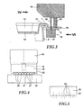
- FIG. 3 The simultaneous production of the weld and the weakening line is shown in FIG. 3 shown in a longitudinal section along the welding flap 9 a detail in the area the welding strap shows.
- the lid 12 is placed on the container 2.
- the lid also has a bent edge 13 on, of a lid plane 14 circumferentially obliquely extends above and the outer end approximately as far from the interior of the container 2 is spaced as the outer end of the bent edge 7 of the container 2.
- the bent edge 13 of the lid on the bent Edge 7 of the container are inverted, with the vertically extending Wall sections at cover 12 and container 2 in the direction parallel to the opening plane deform the container 2 elastically, so that a secure grip is ensured
- This Closure in the form of a snap is interrupted in the field of welding straps.
- the lid plane 14 is below the opening plane of the container.
- cover-side Welding tab 15 on the surface on the container-side welding flap 9.
- the lid 12 has at two diagonally opposite corners two welding flaps 15th on, wherein the corners with the cover-side welding flaps 15 with the corners with the correspond to proportional welding lugs 9.
- Die Cover-side welding flaps 15 also have a substantially triangular Ground plan, with two legs of the adjacent, extended sides of the Dekkels are formed and the top of the triangle is rounded. The base of the triangular Welding flaps 15 is lifted by the over the welding plate plane 15 raised, bent Edge 13 of the lid formed.
- the lid and container are each deep-drawn from polystyrene film, wherein in the thermoforming mold the respective welding flaps 9, 15 are mitgeformt.
- the wall thickness is 1 mm for lid and container.
- the corners of the welding tabs 9 are each about 10mm above the container edge 7, the corners of the welding tabs 15 each about 9mm over the container edge 13.
- Fig. 3 is shown how to weld the two welding flaps 15 a sonotrode 16 perpendicular to the plane of the welding tabs 9, 15 in the material of the welding straps is delivered.
- the lower part 10 of the combined weakening and welding device forms an anvil and an abutment for the sonotrode 16.
- the weakening line is in the embodiment described here both in the Cover-side welding flap 15 as well as in the conditional welding flap 9 attached and is as a rectilinear, perpendicular to the longitudinal direction of the welding tabs 9, 15 extending groove whose base is approximately half the thickness of each cover 12 and container 2 is located. At regular intervals are both grooves perforated with through holes.
- the groove has a substantially rectangular Cross section, the through holes are square.
- the line of weakness is produced by one at the lower part 10 of the weakening and Welding system arranged counter-holder 17, which is substantially the shape of the lower Groove and the passage openings. Lid side becomes the line of weakness by a in the form of the counter-holder 17 substantially corresponding punch 18 formed.
- An ultrasonic head 19 of substantially circular cross-section is outside the Stamp 18 delivered simultaneously with this in the lid-side welding flap 15. He generates ultrasound, through which the two welding tabs 9, 15 at their adjacent Surfaces are welded together.
- the center of the sound source 19 is located on the longitudinal axis of the welding flap 15. The sound source 19 extends approximately half the material thickness of the welding strap 15 less far in the direction perpendicular to the welding tab 15 as the stamp 18th
- a simultaneous welding of the two welding straps 9 and 15 and manufacture the Weld is ensured by the fact that the ultrasonic head 19 and the stamp 18th are attached to the sonotrode 16 and delivered simultaneously.
- the pressure of the punch 18 the welding surface 9 is pressed onto the counter-holder 17.
- the container 2 and lid 12th consists of the sweat pickup 3 is the method for producing the tamper-evident closure completed.
- the result is a tamper-evident closure food container filled with food.
- Lower part 10 and sonotrode 16 of FIG. 4 are in the position shown in FIG. 3, taken at the completion of the weakening line and welding becomes.
- the welding flaps 9 and 15 are not shown.
- the Interface between the welding tabs 9 and 15 runs along the dividing line between lower part 10 and sonotrode 16.
- the passage openings of the weakening line be in the conditional welding lug 9 by webs 20 of the anvil 17 and produced in the cover-side welding strap 15 by webs 21. Between the webs 20 and 21 and the punch 18 are each semi-circular cutouts, which in the case of the sonotrode 16 moved to the lower part 10 complete to form circles 22.
- the diameter of these circles is approximately 1.5 in the embodiment shown mm, the distance between the circle centers 2 mm.
- Fig. 5 shows the punch 18 for simultaneously forming the line of weakness with the Welding separated from the lower part 10.
- the dashed lines 23 is, the semi-circular cutouts between the webs 21 bevelled, so that their diameter widens in the outward direction relative to the welding tab 15 This creates a beveled cut surface on which the fragments of the perforation stick more easily, and the penetrating vertically in the welding lug Stamp 18 is easier to deliver in the material.
- Fig. 6 shows the lower part 10 in a view in the direction of arrow VI of Fig. 3.
- Die Semicircles between the webs 20 widen in the direction of the longitudinal axis of Weld seam 15 to the outside. This results in bevelled cutting edges 24. Der Helix angle of the surfaces 24 is about 20 °.
- the thickness of the stamp of the Welding straps and the width of the anvil 17 is in the longitudinal direction 25th 0.8 mm.
- the outer, lower edge of the cutting surfaces 24 is about 0.25 mm from the Top of the lower part 10 removed. Accordingly, the clear width is the Value of the weakening lines of lid and container also about 0.8mm.
- Fig. 7 shows the lower part 10 in the direction of the arrow VII of Fig. 6, cut by the center of a semicircular recess between the webs 20.
- the shape the counter-holder 17 corresponds, like the punch 18, to the shape of the weakening line, such as it is formed in the conditional welding lug 9.
- FIG. 8 shows a plan view of the cover-side welding tab 15 during welding the welding tabs and when establishing the weakening line.
- the cutting plane runs parallel to the opening plane of the container and cuts stamp 18 and Sound source 19.
- the punch 18 extends perpendicular to the longitudinal direction 25 in a straight line on the welding tab 15.
- two rectangular cuts 26 are attached, one leg parallel to the line of weakness at the inner edge runs. In the direction of the container interior, these cuts 26 extend to the Outer edge of the supply-side welding flap 9.
- the cuts 26 are used for easier tearing of the finished tamper-evident closure. after the Welding flaps 9, 15 were demolished, thanks to the cuts 26 creates a burr-free Corner.
- the incisions 26 extend approximately 1.2 mm perpendicular to the respectively corresponding side edges of the lid. 2
- the tamper-evident closure made in accordance with the embodiment has seven Through openings, which the seven webs 20, 21 of the counter-holder 17 and Stamp 18 correspond.
- welding tabs 9 and 15 can either be bent along the weld line up or down by pivoting or demolished along the line of weakness by means of the cuts 26. Indeed For example, the food container for inspection purposes by Lift at the non-welded points to be opened. Because the ultrasound head 19 seen from inside the container beyond the line of weakness is, by Separating the welding tabs 9, 15 along the line of weakness the weld separated from the food container and the lid 12 is removable from the container 2.
- the design of the bent edges 7, 13 of the lid and container allow closing the lid even after opening the tamper-evident closure. By the absence of welding lugs or their damage is immediately verifiable, whether the food container has been opened before, so manipulated on it.
Landscapes
- Engineering & Computer Science (AREA)
- Mechanical Engineering (AREA)
- Closures For Containers (AREA)
- Lining Or Joining Of Plastics Or The Like (AREA)
- Packages (AREA)
- Packging For Living Organisms, Food Or Medicinal Products That Are Sensitive To Environmental Conditiond (AREA)
Claims (15)
- Procédé de fabrication d'une fermeture inviolable, en particulier pour contenants alimentaires, dans lequel un récipient (2) et un couvercle (12) correspondant, pourvus chacun d'au moins une patte de soudage (9, 15), sont assemblés en des points qui se correspondent, après le remplissage du récipient avec des produits alimentaires, et le couvercle est soudé avec le récipient rempli au niveau des pattes de soudage au moyen d'un dispositif de soudage par ultrasons (10, 16, 17, 18, 19), une ouverture du contenant alimentaire soudé détruisant au moins en partie ledit contenant alimentaire, au moins une ligne d'affaiblissement, le long de laquelle on peut déchirer les pattes de soudage soudées pour ouvrir le contenant alimentaire, étant réalisée dans la région des pattes de soudage après le remplissage du récipient, caractérisé en ce qu'à l'aide du dispositif de soudage par ultrasons (10, 16, 17, 18, 19), on réalise mécaniquement la ligne d'affaiblissement en même temps que le soudage des pattes de soudage (9, 15), tant côté couvercle que côté récipient.
- Procédé selon la revendication 1, caractérisé en ce que pour réaliser mécaniquement la ligne d'affaiblissement, on avance dans la patte de soudage (9, 15) appropriée, côté couvercle et côté récipient, un poinçon (17, 18), dont la conformation correspond à la ligne d'affaiblissement, et on forme ainsi la ligne d'affaiblissement.
- Procédé selon la revendication 1 ou 2, caractérisé en ce que pour réaliser la ligne d'affaiblissement, on perfore, au moins par tronçons, au moins une patte de soudage (9, 15).
- Procédé selon l'une des revendications précédentes, caractérisé en ce que pour réaliser la ligne d'affaiblissement, on aménage, au moins par tronçons, un évidement en forme de rainure sur au moins une patte de soudage (9, 15).
- Procédé selon l'une des revendications précédentes, caractérisé en ce qu'on fabrique le couvercle (12) et/ou le récipient (2), de préférence en même temps que la patte de soudage (9, 15), par emboutissage, par exemple à partir d'une feuille de polystyrène.
- Dispositif de soudage par ultrasons (10, 16, 17, 18, 19) pour la mise en oeuvre du procédé selon l'une des revendications 1 à 5, lequel dispositif peut être transféré d'une position de soudage, dans laquelle une partie (15) côté couvercle d'un contenant alimentaire peut être soudée à une partie (9) côté récipient du contenant alimentaire par une tête à ultrasons (19) montée sur le dispositif de soudage par ultrasons, dans une position de repos dans laquelle on peut installer le contenant alimentaire dans le dispositif de soudage par ultrasons en le plaçant au moins en partie dans un logement, caractérisé en ce que le dispositif de soudage par ultrasons (10, 16, 17, 18, 19) comporte au moins un poinçon (17, 18) à l'aide duquel on peut, dans la position de soudage, réaliser mécaniquement la ligne d'affaiblissement aussi bien côté couvercle que côté récipient.
- Dispositif de soudage par ultrasons selon la revendication 6, caractérisé en ce que le poinçon (17, 18) présente une face tournée vers le contenant alimentaire (2, 12), une face correspondant sensiblement à la forme de la ligne d'affaiblissement sur le contenant alimentaire (2, 12) et que dans la position de soudage, il est avancé dans le contenant alimentaire (2, 12) pour fabriquer la ligne d'affaiblissement et est écarté dudit contenant alimentaire (2, 12) dans la position de repos.
- Dispositif de soudage par ultrasons selon la revendication 6 ou 7, caractérisé en ce que le dispositif de soudage par ultrasons (10, 16, 17, 18, 19) présente un serre-flan (17, 18) qui est situé en vis-à-vis du poinçon (17, 18) par rapport au contenant alimentaire (2, 12), dont la face tournée vers le contenant alimentaire (2, 12) correspond sensiblement à la forme de la ligne d'affaiblissement sur le contenant alimentaire (2, 12) et qui, dans la position de soudage, est avancé dans le contenant alimentaire pour fabriquer la ligne d'affaiblissement et est écarté dudit contenant alimentaire dans la position de repos.
- Dispositif de soudage par ultrasons selon l'une des revendications 6 à 8, caractérisé en ce que la face du serre-flan et/ou la face du poinçon sont pour l'essentiel rectangulaires en coupe transversale le long d'un prolongement longitudinal (25) d'une patte de soudage (9, 15) du contenant alimentaire (2, 12).
- Dispositif de soudage par ultrasons selon l'une des revendications 6 à 9, caractérisé en ce que la face du serre-flan et/ou la face du poinçon s'étendent sur toute la patte de soudage (9, 15), transversalement au prolongement longitudinal (25) de la patte de soudage (9, 15) du contenant alimentaire (2, 12).
- Dispositif de soudage par ultrasons selon l'une des revendications 6 à 10, caractérisé en ce que la face du serre-flan et/ou la face du poinçon, pour produire une perforation, sont pourvues de nervures (20, 21) qui sont séparées les unes des autres par des évidements (22).
- Dispositif de soudage par ultrasons selon l'une des revendications 6 à 11, caractérisé en ce que les évidements (22) sont à angle droit ou sont coudés transversalement au prolongement longitudinal (25) de la patte de soudage (9, 15).
- Dispositif de soudage par ultrasons selon l'une des revendications 6 à 12, caractérisé en ce que les nervures (20, 21) et/ou les évidements (22) sont biseautés.
- Dispositif de soudage par ultrasons selon l'une des revendications 6 à 12, caractérisé en ce que la face du poinçon et la face du serre-flan présentent des formes qui se correspondent sensiblement et que leurs nervures (20, 21) sont mutuellement en contact dans la position de soudage.
- Dispositif de soudage par ultrasons selon l'une des revendications 6 à 13, caractérisé en ce que la face du serre-flan et/ou la face du poinçon présentent, dans la direction du prolongement longitudinal (25) de la patte de soudage (9, 15), une largeur comprise entre 0,5 et 2 mm, de préférence comprise entre 0,7 et 1 mm.
Applications Claiming Priority (2)
| Application Number | Priority Date | Filing Date | Title |
|---|---|---|---|
| DE19824785A DE19824785A1 (de) | 1998-06-03 | 1998-06-03 | Verfahren zum Herstellen eines Originalitätsverschlusses und Lebensmittelbehälter |
| DE19824785 | 1998-06-03 |
Publications (2)
| Publication Number | Publication Date |
|---|---|
| EP0962398A1 EP0962398A1 (fr) | 1999-12-08 |
| EP0962398B1 true EP0962398B1 (fr) | 2003-04-23 |
Family
ID=7869771
Family Applications (1)
| Application Number | Title | Priority Date | Filing Date |
|---|---|---|---|
| EP99109076A Expired - Lifetime EP0962398B1 (fr) | 1998-06-03 | 1999-05-07 | Procédé de fabrication d'une fermeture inviolable et dispositif de soudage par ultrasons |
Country Status (3)
| Country | Link |
|---|---|
| EP (1) | EP0962398B1 (fr) |
| AT (1) | ATE238204T1 (fr) |
| DE (2) | DE19824785A1 (fr) |
Cited By (1)
| Publication number | Priority date | Publication date | Assignee | Title |
|---|---|---|---|---|
| US10919659B2 (en) | 2018-11-07 | 2021-02-16 | Bellisio Foods, Inc. | Systems and methods for packaging food products in containers and containers packaged by such systems and methods |
Families Citing this family (8)
| Publication number | Priority date | Publication date | Assignee | Title |
|---|---|---|---|---|
| EP1340693A1 (fr) * | 2002-02-26 | 2003-09-03 | Cryovac, Inc. | Emballage à ouverture facile |
| EP1786696A4 (fr) * | 2005-05-06 | 2009-04-29 | Huhtamaki Australia Pty Ltd | Recipient a couvercle a charniere avec un moyen de revelation d'effraction frangible |
| DE102006005700A1 (de) * | 2006-02-08 | 2007-08-09 | Robert Bosch Gmbh | Vorrichtung und Verfahren zum Entfernen einer Abdeckfolie von einem Behälter |
| ATE493347T1 (de) | 2008-02-29 | 2011-01-15 | Dirk Maes | Verbindungsring für mindestens zwei übereinander gelagerte behälter |
| DE102009026795A1 (de) * | 2009-06-05 | 2010-12-09 | Fürst GmbH | Kunststoffbehälter zur Aufnahme von Lebensmitteln |
| EP2272764B1 (fr) * | 2009-07-10 | 2012-10-24 | Rainer Naroska Verpackungsmaschinen GmbH & Co. KG | Procédé et dispositif pour sceller un opercule à déchirer sur un élément d'emballage |
| DE102014201329A1 (de) * | 2014-01-24 | 2015-07-30 | Multivac Sepp Haggenmüller Gmbh & Co. Kg | Tiefziehverpackungsmaschine mit Ultraschalleinrichtung |
| CN112158400A (zh) * | 2020-09-03 | 2021-01-01 | 昆山宣润精密机械有限公司 | 锯条自动收料包装机构 |
Family Cites Families (10)
| Publication number | Priority date | Publication date | Assignee | Title |
|---|---|---|---|---|
| GB1206667A (en) * | 1968-05-15 | 1970-09-30 | Sidaplax S A | Production of packages |
| GB2040267A (en) * | 1979-01-22 | 1980-08-28 | Drg Uk Ltd | Container having pilfer indication means |
| GB8704434D0 (en) * | 1987-02-25 | 1987-04-01 | Peerless Plastics Packaging | Lidded container |
| IT219731Z2 (it) * | 1990-06-13 | 1993-04-28 | Vassoio con copertura dotata di chiusura di garanzia. | |
| GB2260969B (en) * | 1991-10-17 | 1995-01-25 | Drg Plastics Ltd | Tamper-evident container |
| CH686939A5 (de) * | 1992-03-05 | 1996-08-15 | Alusuisse Lonza Services Ag | Verfahren zur Herstellung von Durchdrueckpackungen |
| US5345747A (en) * | 1993-02-19 | 1994-09-13 | Raque Food Systems, Inc. | Ultrasonic sealing apparatus and method |
| DE4410206A1 (de) * | 1994-03-24 | 1995-09-28 | Tetra Laval Holdings & Finance | Fließmittelpackung mit teilweise abreißbarer Greiflasche |
| US5564255A (en) * | 1994-09-28 | 1996-10-15 | Tetra Laval Holdings & Finance S.A. | Apparatus and method for sealing and creasing gabled containers |
| BR9601953A (pt) * | 1996-07-16 | 1998-09-29 | Silveira Alexandre Rey | Embalagem inviolável com lacre indiciador de adulteração ou violação |
-
1998
- 1998-06-03 DE DE19824785A patent/DE19824785A1/de not_active Ceased
-
1999
- 1999-05-07 EP EP99109076A patent/EP0962398B1/fr not_active Expired - Lifetime
- 1999-05-07 AT AT99109076T patent/ATE238204T1/de not_active IP Right Cessation
- 1999-05-07 DE DE59905134T patent/DE59905134D1/de not_active Expired - Fee Related
Cited By (2)
| Publication number | Priority date | Publication date | Assignee | Title |
|---|---|---|---|---|
| US10919659B2 (en) | 2018-11-07 | 2021-02-16 | Bellisio Foods, Inc. | Systems and methods for packaging food products in containers and containers packaged by such systems and methods |
| US11247799B2 (en) | 2018-11-07 | 2022-02-15 | Bellisio Foods, Inc. | Food containers |
Also Published As
| Publication number | Publication date |
|---|---|
| ATE238204T1 (de) | 2003-05-15 |
| DE59905134D1 (de) | 2003-05-28 |
| DE19824785A1 (de) | 1999-12-09 |
| EP0962398A1 (fr) | 1999-12-08 |
Similar Documents
| Publication | Publication Date | Title |
|---|---|---|
| DE69918993T2 (de) | Verschliessbare Öffnungsvorrichtung für Packungen für fliessfähige Nahrungsmittel | |
| EP2909092B1 (fr) | Élément verseur refermable pour un emballage, et poinçon faisant partie d'une roue à poinçons rotative d'une machine d'emballage et permettant de recevoir un tel élément verseur, et combinaison entre l'élément verseur et le poinçon | |
| EP0200877B1 (fr) | Emballage pour liquides ainsi que procédé et dispositif pour sa fabrication | |
| EP0190577A2 (fr) | Emballage pour liquides avec bec verseur | |
| DE19504157A1 (de) | Beutel | |
| EP0962398B1 (fr) | Procédé de fabrication d'une fermeture inviolable et dispositif de soudage par ultrasons | |
| DE2939093C2 (de) | Flüssigkeitspackung mit Ausgieß- und Lufteintrittsöffnung | |
| EP0223094B1 (fr) | Emballage pour liquides formé d'un matériau enduit de matière plastique | |
| DE1809000C3 (de) | Behälter mit Vollaufreißdeckel aus Blech | |
| DE202016008464U1 (de) | Multipack-Behälter | |
| DE19651242A1 (de) | Amboß einer Ultraschall-Siegeleinheit | |
| DE2751351A1 (de) | Verfahren zur herstellung eines dichten verschlusses an einem verpackungsbehaelter fuer fluessigen inhalt | |
| EP0386416A1 (fr) | Emballage facile à ouvrir | |
| DE3013098A1 (de) | Schneidwerkzeug zum einbringen einer aufreisskerbe in die etikettenschicht eines mehrschichtbehaelters | |
| AT397071B (de) | Behälterzuschnitt aus faltbarem flachmaterial | |
| DE2623404A1 (de) | Parallelepipedfoermiger verpackungsbehaelter und verfahren zu dessen herstellung | |
| DE3100110A1 (de) | Behaelterzuschnitt aus faltbarem flachmaterial | |
| EP0700836A2 (fr) | Emballage en matériau plastique avec couvercle à charnière et procédé et dispositif pour sa fabrication | |
| DE102006005873A1 (de) | Wandflächenteil, Transportbehälter und Tiefziehwerkzeug | |
| DE1904088A1 (de) | Behaelter aus Kunststoff fuer Joghurt oder aehnliche Ware | |
| DE3037067C2 (de) | Flüssigkeitspackung und Vorrichtung zur Herstellung derselben | |
| EP3072831A1 (fr) | Emballage refermable | |
| DE102009037667B4 (de) | Verfahren zum Verpacken von Produkten | |
| CH627703A5 (en) | Frangible container closure, method for its manufacture, and use | |
| DE69005600T2 (de) | Verfahren zum Herstellen einer Verpackung, die so hergestellte Verpackung und Vorrichtung zur Durchführung des Verfahrens. |
Legal Events
| Date | Code | Title | Description |
|---|---|---|---|
| PUAI | Public reference made under article 153(3) epc to a published international application that has entered the european phase |
Free format text: ORIGINAL CODE: 0009012 |
|
| AK | Designated contracting states |
Kind code of ref document: A1 Designated state(s): AT BE CH DE FR GB LI LU NL |
|
| AX | Request for extension of the european patent |
Free format text: AL;LT;LV;MK;RO;SI |
|
| 17P | Request for examination filed |
Effective date: 19991230 |
|
| AKX | Designation fees paid |
Free format text: AT BE CH DE FR GB LI LU NL |
|
| 17Q | First examination report despatched |
Effective date: 20011217 |
|
| GRAH | Despatch of communication of intention to grant a patent |
Free format text: ORIGINAL CODE: EPIDOS IGRA |
|
| RTI1 | Title (correction) |
Free format text: METHOD FOR MANUFACTURING A TAMPER-EVIDENT CLOSURE AND ULTRASONIC WELDING APPARATUS |
|
| GRAH | Despatch of communication of intention to grant a patent |
Free format text: ORIGINAL CODE: EPIDOS IGRA |
|
| GRAA | (expected) grant |
Free format text: ORIGINAL CODE: 0009210 |
|
| AK | Designated contracting states |
Designated state(s): AT BE CH DE FR GB LI LU NL |
|
| PG25 | Lapsed in a contracting state [announced via postgrant information from national office to epo] |
Ref country code: NL Free format text: LAPSE BECAUSE OF FAILURE TO SUBMIT A TRANSLATION OF THE DESCRIPTION OR TO PAY THE FEE WITHIN THE PRESCRIBED TIME-LIMIT Effective date: 20030423 |
|
| REG | Reference to a national code |
Ref country code: GB Ref legal event code: FG4D Free format text: NOT ENGLISH |
|
| REG | Reference to a national code |
Ref country code: CH Ref legal event code: EP |
|
| PG25 | Lapsed in a contracting state [announced via postgrant information from national office to epo] |
Ref country code: LU Free format text: LAPSE BECAUSE OF NON-PAYMENT OF DUE FEES Effective date: 20030507 |
|
| GBT | Gb: translation of ep patent filed (gb section 77(6)(a)/1977) |
Effective date: 20030423 |
|
| REG | Reference to a national code |
Ref country code: CH Ref legal event code: NV Representative=s name: BOVARD AG PATENTANWAELTE |
|
| REF | Corresponds to: |
Ref document number: 59905134 Country of ref document: DE Date of ref document: 20030528 Kind code of ref document: P |
|
| PG25 | Lapsed in a contracting state [announced via postgrant information from national office to epo] |
Ref country code: BE Free format text: LAPSE BECAUSE OF NON-PAYMENT OF DUE FEES Effective date: 20030531 |
|
| NLV1 | Nl: lapsed or annulled due to failure to fulfill the requirements of art. 29p and 29m of the patents act | ||
| BERE | Be: lapsed |
Owner name: *BELLAPLAST HOLDING A.G. Effective date: 20030531 |
|
| ET | Fr: translation filed | ||
| PLBE | No opposition filed within time limit |
Free format text: ORIGINAL CODE: 0009261 |
|
| STAA | Information on the status of an ep patent application or granted ep patent |
Free format text: STATUS: NO OPPOSITION FILED WITHIN TIME LIMIT |
|
| 26N | No opposition filed |
Effective date: 20040126 |
|
| PGFP | Annual fee paid to national office [announced via postgrant information from national office to epo] |
Ref country code: AT Payment date: 20070521 Year of fee payment: 9 |
|
| PGFP | Annual fee paid to national office [announced via postgrant information from national office to epo] |
Ref country code: CH Payment date: 20070522 Year of fee payment: 9 |
|
| PGFP | Annual fee paid to national office [announced via postgrant information from national office to epo] |
Ref country code: DE Payment date: 20070628 Year of fee payment: 9 |
|
| PGFP | Annual fee paid to national office [announced via postgrant information from national office to epo] |
Ref country code: GB Payment date: 20070611 Year of fee payment: 9 |
|
| PGFP | Annual fee paid to national office [announced via postgrant information from national office to epo] |
Ref country code: FR Payment date: 20070518 Year of fee payment: 9 |
|
| REG | Reference to a national code |
Ref country code: CH Ref legal event code: PL |
|
| GBPC | Gb: european patent ceased through non-payment of renewal fee |
Effective date: 20080507 |
|
| PG25 | Lapsed in a contracting state [announced via postgrant information from national office to epo] |
Ref country code: LI Free format text: LAPSE BECAUSE OF NON-PAYMENT OF DUE FEES Effective date: 20080531 Ref country code: CH Free format text: LAPSE BECAUSE OF NON-PAYMENT OF DUE FEES Effective date: 20080531 |
|
| PG25 | Lapsed in a contracting state [announced via postgrant information from national office to epo] |
Ref country code: AT Free format text: LAPSE BECAUSE OF NON-PAYMENT OF DUE FEES Effective date: 20080507 |
|
| REG | Reference to a national code |
Ref country code: FR Ref legal event code: ST Effective date: 20090119 |
|
| PG25 | Lapsed in a contracting state [announced via postgrant information from national office to epo] |
Ref country code: FR Free format text: LAPSE BECAUSE OF NON-PAYMENT OF DUE FEES Effective date: 20080602 Ref country code: DE Free format text: LAPSE BECAUSE OF NON-PAYMENT OF DUE FEES Effective date: 20081202 |
|
| PG25 | Lapsed in a contracting state [announced via postgrant information from national office to epo] |
Ref country code: GB Free format text: LAPSE BECAUSE OF NON-PAYMENT OF DUE FEES Effective date: 20080507 |