EP0962713A2 - Halterung für Strahlungsheizkörper - Google Patents
Halterung für Strahlungsheizkörper Download PDFInfo
- Publication number
- EP0962713A2 EP0962713A2 EP99109336A EP99109336A EP0962713A2 EP 0962713 A2 EP0962713 A2 EP 0962713A2 EP 99109336 A EP99109336 A EP 99109336A EP 99109336 A EP99109336 A EP 99109336A EP 0962713 A2 EP0962713 A2 EP 0962713A2
- Authority
- EP
- European Patent Office
- Prior art keywords
- jaw
- upright
- support according
- shaped
- jaws
- Prior art date
- Legal status (The legal status is an assumption and is not a legal conclusion. Google has not performed a legal analysis and makes no representation as to the accuracy of the status listed.)
- Granted
Links
- 230000000284 resting effect Effects 0.000 claims abstract description 5
- 238000010438 heat treatment Methods 0.000 description 4
- 239000002184 metal Substances 0.000 description 2
- 238000003466 welding Methods 0.000 description 2
- 230000015572 biosynthetic process Effects 0.000 description 1
- JEIPFZHSYJVQDO-UHFFFAOYSA-N iron(III) oxide Inorganic materials O=[Fe]O[Fe]=O JEIPFZHSYJVQDO-UHFFFAOYSA-N 0.000 description 1
- 230000000670 limiting effect Effects 0.000 description 1
- 239000000463 material Substances 0.000 description 1
- 230000004048 modification Effects 0.000 description 1
- 238000012986 modification Methods 0.000 description 1
- 238000010422 painting Methods 0.000 description 1
- 238000000926 separation method Methods 0.000 description 1
Images


Classifications
-
- F—MECHANICAL ENGINEERING; LIGHTING; HEATING; WEAPONS; BLASTING
- F24—HEATING; RANGES; VENTILATING
- F24D—DOMESTIC- OR SPACE-HEATING SYSTEMS, e.g. CENTRAL HEATING SYSTEMS; DOMESTIC HOT-WATER SUPPLY SYSTEMS; ELEMENTS OR COMPONENTS THEREFOR
- F24D19/00—Details
- F24D19/02—Arrangement of mountings or supports for radiators
- F24D19/024—Functioning details of supporting means for radiators
- F24D19/0246—Means for moving the radiator vertically to adjust the radiator position
-
- F—MECHANICAL ENGINEERING; LIGHTING; HEATING; WEAPONS; BLASTING
- F24—HEATING; RANGES; VENTILATING
- F24D—DOMESTIC- OR SPACE-HEATING SYSTEMS, e.g. CENTRAL HEATING SYSTEMS; DOMESTIC HOT-WATER SUPPLY SYSTEMS; ELEMENTS OR COMPONENTS THEREFOR
- F24D19/00—Details
- F24D19/02—Arrangement of mountings or supports for radiators
-
- F—MECHANICAL ENGINEERING; LIGHTING; HEATING; WEAPONS; BLASTING
- F24—HEATING; RANGES; VENTILATING
- F24D—DOMESTIC- OR SPACE-HEATING SYSTEMS, e.g. CENTRAL HEATING SYSTEMS; DOMESTIC HOT-WATER SUPPLY SYSTEMS; ELEMENTS OR COMPONENTS THEREFOR
- F24D19/00—Details
- F24D19/02—Arrangement of mountings or supports for radiators
- F24D19/0203—Types of supporting means
- F24D19/0213—Floor mounted supporting means
-
- F—MECHANICAL ENGINEERING; LIGHTING; HEATING; WEAPONS; BLASTING
- F24—HEATING; RANGES; VENTILATING
- F24D—DOMESTIC- OR SPACE-HEATING SYSTEMS, e.g. CENTRAL HEATING SYSTEMS; DOMESTIC HOT-WATER SUPPLY SYSTEMS; ELEMENTS OR COMPONENTS THEREFOR
- F24D19/00—Details
- F24D19/02—Arrangement of mountings or supports for radiators
- F24D19/024—Functioning details of supporting means for radiators
- F24D19/0256—Radiators clamped by supporting means
-
- F—MECHANICAL ENGINEERING; LIGHTING; HEATING; WEAPONS; BLASTING
- F24—HEATING; RANGES; VENTILATING
- F24D—DOMESTIC- OR SPACE-HEATING SYSTEMS, e.g. CENTRAL HEATING SYSTEMS; DOMESTIC HOT-WATER SUPPLY SYSTEMS; ELEMENTS OR COMPONENTS THEREFOR
- F24D19/00—Details
- F24D19/02—Arrangement of mountings or supports for radiators
- F24D19/0203—Types of supporting means
-
- F—MECHANICAL ENGINEERING; LIGHTING; HEATING; WEAPONS; BLASTING
- F24—HEATING; RANGES; VENTILATING
- F24D—DOMESTIC- OR SPACE-HEATING SYSTEMS, e.g. CENTRAL HEATING SYSTEMS; DOMESTIC HOT-WATER SUPPLY SYSTEMS; ELEMENTS OR COMPONENTS THEREFOR
- F24D2220/00—Components of central heating installations excluding heat sources
- F24D2220/20—Heat consumers
- F24D2220/2009—Radiators
- F24D2220/2054—Panel radiators with or without extended convection surfaces
Definitions
- the present invention relates to a support for radiating panels.
- Conventional supports for radiating panels are substantially constituted by an upright with means for resting on the ground or for cantilevered fixing and means for fixing to the radiating panel.
- tubular upright is disclosed to be inserted between the shaped regions of the convection lamina of a radiating panel that form two vertical tubular air passage gaps.
- a sleeve is slidingly coupled to the tubular upright in a downward region and supports one or two wings to be inserted in the gaps which are located adjacent to the upright when installed.
- a screw acts between the sleeve and the upright and engages a through hole of the sleeve which is perpendicular to the plane of arrangement formed by the radiating panel; said screw mutually divaricates the wing or wings and the upright at right angles to the plate, so that the upright is pushed toward the plate and the wing or wings are pushed in the opposite direction and therefore against the wall of the corresponding gap.
- the support has the drawback that the divaricating action between the upright and the wing or wings associated therewith entails a traction between the convection laminae that form the gaps and the heating body that constitutes the panel in the regions where they are mutually joined, usually by spot welding.
- Traction is applied in particular to the joining portions that lies opposite with respect to the support.
- the spot welding is not particularly strong, because it is provided merely to keep the convection lamina joined to the heating body, the traction due to the divarication of the components of the support may easily lead to the separation of the spot welds.
- the traction in any case produces a deformation of the shape of the gaps, accordingly ruining their painting and causing rust formation.
- the aim of the present invention is to provide a support for radiating panels which eliminates the above drawbacks of conventional supports.
- a primary object is to provide a support for radiating panels whose action is applied without subjecting the components of the panel to stresses.
- Another important object is to provide a support whose action is applied without deforming the components of the panel.
- Another important object is to provide a support which is particularly handy and simple to use.
- Another object is to provide a support which is constructively simple and can be manufactured at a low cost with conventional equipment and machines.
- a support for radiating panels comprising an upright with means for resting on the ground or for cantilevered fixing and means for fixing to the panel, characterized in that said upright is adjustable and said means for fixing to a radiating panel comprise two mutually articulated elements which define respective shaped jaws between which a convection lamina can be inserted and locked, said jaws being associated by screw-type fastening means which act at right angles to the articulation axis in a region available to the action of the user and one of said articulated elements being rigidly coupled to said upright.
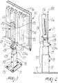
- a support for radiating panels comprises an upright 10, which in this case is welded below a plate 11 for resting on the ground but can be provided with cantilevered fixing means of the bracket type or the like, and means for fixing to the radiating panel 12 which are generally designated by the reference numeral 13.
- the radiating panel 12 in this case, is of the type constituted by a plate-like heating body 14 to which a convection lamina 15 is spot-welded on one face; said lamina is shaped so as to form a plurality of vertical corrugations which form gaps 16 having a quadrangular cross-section, particularly for example a trapezoidal one.
- the upright 10 is telescopic and is constituted in practice by two tubular elements, respectively designated by the reference numerals 17 and 18, which have for example a rectangular cross-section and are inserted in each other.
- the two elements 17 and 18 are associated by screws 19 which act between them so as to produce mutual locking.
- the means for fixing to the panel 12 further comprise two elements 20 and 21 which are mutually articulated by means of a threaded pivot 22 and form respective contoured jaws which are designated by the same reference numerals 20 and 21.
- the first jaw 20 is constituted by an elongated lamina 23 which is shaped, by subjecting a metal plate to blanking and plastic deformation, so as to have a cross-section which is omega-shaped over most of its extension.
- the jaw 20 therefore has two co-planar flaps or wings 24 and 25.
- the lamina 23 is butt-welded, with a U-shaped portion 23a, to the tubular element 17 of the upright 10 and is therefore axially rigidly coupled thereto.
- the jaw 21 is instead constituted, in this case, by two parallel blades 26 and 27 which are joined one another by a U-shaped portion 28 which is monolithic therewith, the assembly being obtained by subjecting a metal plate to blanking and plastic deformation.
- the U-shaped portion 28 is arranged in the portion 23a of the jaw 21 and has a flat portion 29 which is perpendicular to the blades 26 and 27 and is crossed by a through hole 30.
- the two blades 26 and 27 are arranged so that the jaw 20 is located therebetween and so that they cooperate with the flaps 24 and 25.
- a screw 31 passes through the through hole 30 and engages a diametrical threaded hole 32 of a cylindrical pivot 33 which is inserted in holes 34 between the wings of the U-shaped portion 23a of the jaw 20.
- the shape of the jaws 20 and 21 causes them to be first-class levers which therefore have a centrally located fulcrum.
- the jaw 20 is arranged outside the radiating panel 12 between two adjacent gaps 16, while the blades 26 and 27 of the jaw 21 are inserted in said gaps 16.
- the regions with which the blades 26 and 27 and the flaps 24 and 25 make contact with a convection lamina 15 can be continuously or partially covered with a trim.
- said trim can be constituted by a U-shaped element which is cut to size and placed so as to straddle the edges of the blades 26 and 27 and of the flaps 24 and 25 so as to form the elements designated by the reference numerals 35, 36, 37 and 38 in Figure 7.
- the materials employed may be any according to requirements.
Landscapes
- Engineering & Computer Science (AREA)
- Physics & Mathematics (AREA)
- Thermal Sciences (AREA)
- Chemical & Material Sciences (AREA)
- Combustion & Propulsion (AREA)
- Mechanical Engineering (AREA)
- General Engineering & Computer Science (AREA)
- Floor Finish (AREA)
- Central Heating Systems (AREA)
- Laminated Bodies (AREA)
- Yarns And Mechanical Finishing Of Yarns Or Ropes (AREA)
- Baking, Grill, Roasting (AREA)
- Vehicle Step Arrangements And Article Storage (AREA)
- Details Of Aerials (AREA)
- Non-Reversible Transmitting Devices (AREA)
- Forklifts And Lifting Vehicles (AREA)
Priority Applications (1)
| Application Number | Priority Date | Filing Date | Title |
|---|---|---|---|
| SI9930692T SI0962713T1 (en) | 1998-06-02 | 1999-05-31 | Support for radiating panels |
Applications Claiming Priority (2)
| Application Number | Priority Date | Filing Date | Title |
|---|---|---|---|
| ITPD980140 | 1998-06-02 | ||
| IT98PD000140A ITPD980140A1 (it) | 1998-06-02 | 1998-06-02 | Supporto per piastre radianti |
Publications (3)
| Publication Number | Publication Date |
|---|---|
| EP0962713A2 true EP0962713A2 (de) | 1999-12-08 |
| EP0962713A3 EP0962713A3 (de) | 2001-02-28 |
| EP0962713B1 EP0962713B1 (de) | 2004-08-18 |
Family
ID=11392242
Family Applications (1)
| Application Number | Title | Priority Date | Filing Date |
|---|---|---|---|
| EP99109336A Expired - Lifetime EP0962713B1 (de) | 1998-06-02 | 1999-05-31 | Halterung für Strahlungsheizkörper |
Country Status (5)
| Country | Link |
|---|---|
| EP (1) | EP0962713B1 (de) |
| AT (1) | ATE274172T1 (de) |
| DE (1) | DE69919448T2 (de) |
| IT (1) | ITPD980140A1 (de) |
| SI (1) | SI0962713T1 (de) |
Cited By (5)
| Publication number | Priority date | Publication date | Assignee | Title |
|---|---|---|---|---|
| WO2001075370A1 (en) * | 2000-04-04 | 2001-10-11 | Mb S.R.L. | Device for supporting panel radiators |
| CN100455907C (zh) * | 2005-01-14 | 2009-01-28 | 北新集团建材股份有限公司 | 一种散热器落地支架 |
| GB2524278A (en) * | 2014-03-19 | 2015-09-23 | William Ernest Edward Bowyer | Thermally efficient radiator MK1 |
| GB2524280A (en) * | 2014-03-19 | 2015-09-23 | William Ernest Edward Bowyer | Thermally efficient universal radiator mounting |
| IT201900007048A1 (it) * | 2019-05-21 | 2020-11-21 | Mb Srl | Supporto perfezionato per piastre radianti |
Families Citing this family (1)
| Publication number | Priority date | Publication date | Assignee | Title |
|---|---|---|---|---|
| CN108488897A (zh) * | 2018-03-09 | 2018-09-04 | 黄永怀 | 一种便于调节高度的电暖器 |
Family Cites Families (2)
| Publication number | Priority date | Publication date | Assignee | Title |
|---|---|---|---|---|
| DE29604090U1 (de) * | 1996-03-05 | 1997-07-03 | H.G. Gottbehüt GmbH & Co. KG, 42551 Velbert | Standkonsole |
| DE19624586A1 (de) * | 1996-06-20 | 1998-01-02 | Wemefa Horst Christopeit Gmbh | Halterung, wie Standkonsole für mit Konvektorblechen versehene ein- oder mehrlagige Plattenheizkörper |
-
1998
- 1998-06-02 IT IT98PD000140A patent/ITPD980140A1/it unknown
-
1999
- 1999-05-31 EP EP99109336A patent/EP0962713B1/de not_active Expired - Lifetime
- 1999-05-31 DE DE69919448T patent/DE69919448T2/de not_active Expired - Lifetime
- 1999-05-31 AT AT99109336T patent/ATE274172T1/de active
- 1999-05-31 SI SI9930692T patent/SI0962713T1/xx unknown
Cited By (6)
| Publication number | Priority date | Publication date | Assignee | Title |
|---|---|---|---|---|
| WO2001075370A1 (en) * | 2000-04-04 | 2001-10-11 | Mb S.R.L. | Device for supporting panel radiators |
| CN100455907C (zh) * | 2005-01-14 | 2009-01-28 | 北新集团建材股份有限公司 | 一种散热器落地支架 |
| GB2524278A (en) * | 2014-03-19 | 2015-09-23 | William Ernest Edward Bowyer | Thermally efficient radiator MK1 |
| GB2524280A (en) * | 2014-03-19 | 2015-09-23 | William Ernest Edward Bowyer | Thermally efficient universal radiator mounting |
| IT201900007048A1 (it) * | 2019-05-21 | 2020-11-21 | Mb Srl | Supporto perfezionato per piastre radianti |
| EP3742058A1 (de) * | 2019-05-21 | 2020-11-25 | MB S.r.l. | Träger für strahlungsplatten |
Also Published As
| Publication number | Publication date |
|---|---|
| DE69919448T2 (de) | 2005-09-08 |
| DE69919448D1 (de) | 2004-09-23 |
| EP0962713B1 (de) | 2004-08-18 |
| EP0962713A3 (de) | 2001-02-28 |
| ITPD980140A1 (it) | 1999-12-02 |
| SI0962713T1 (en) | 2005-02-28 |
| ATE274172T1 (de) | 2004-09-15 |
Similar Documents
| Publication | Publication Date | Title |
|---|---|---|
| US5810303A (en) | Stud bracket to mount a wiring box to a stud | |
| CA2266182C (en) | Mounting bracket and supporting brace | |
| JP3368374B2 (ja) | 金属屋根用取付け金具 | |
| US4135337A (en) | Mounting means for electric outlet box | |
| US4263472A (en) | Electrical box | |
| EP3523490B1 (de) | Deckrahmensystem | |
| CA2391880C (en) | Apparatus for reinforcing a portion of a metal joist adjacent an opening therethrough and methods for forming reinforced openings in metal support members | |
| US4021988A (en) | Metal frame construction | |
| US20180159308A1 (en) | Mounting brace assembly for mounting an electrical box | |
| US20060065805A1 (en) | Clamp | |
| EP0962713A2 (de) | Halterung für Strahlungsheizkörper | |
| US4682460A (en) | Open web structural support mounting bracket and length adjustable web member | |
| US4650085A (en) | Enclosure structure for circuit breaker assemblies and similar apparatus | |
| GB2136458A (en) | Heald frame | |
| JP5185215B2 (ja) | ガス栓の取付金具 | |
| KR101846811B1 (ko) | 건축외장패널용 지지장치 | |
| EP0750708B1 (de) | Rahmen | |
| JP7340253B2 (ja) | 屋根用雪止め装置 | |
| KR20150001626A (ko) | 다기능 빔 클램프 | |
| CA2211583C (en) | Stud bracket | |
| JPH11229565A (ja) | 折板支持具 | |
| JP6876388B2 (ja) | 建築用支持具及びその支持具を備えた二層屋根 | |
| JP2015048637A (ja) | 取付器具 | |
| JPH0647045Y2 (ja) | 支持梁の固定具 | |
| JP7223440B2 (ja) | 等電位ボンディング金具 |
Legal Events
| Date | Code | Title | Description |
|---|---|---|---|
| PUAI | Public reference made under article 153(3) epc to a published international application that has entered the european phase |
Free format text: ORIGINAL CODE: 0009012 |
|
| AK | Designated contracting states |
Kind code of ref document: A2 Designated state(s): AT BE CH DE DK ES FI FR GB GR IE IT LI NL SE |
|
| AX | Request for extension of the european patent |
Free format text: AL;LT;LV;MK;RO;SI |
|
| PUAL | Search report despatched |
Free format text: ORIGINAL CODE: 0009013 |
|
| AK | Designated contracting states |
Kind code of ref document: A3 Designated state(s): AT BE CH CY DE DK ES FI FR GB GR IE IT LI LU MC NL PT SE |
|
| AX | Request for extension of the european patent |
Free format text: AL;LT;LV;MK;RO;SI |
|
| 17P | Request for examination filed |
Effective date: 20010803 |
|
| AKX | Designation fees paid |
Free format text: AT BE CH DE DK ES FI FR GB GR IE IT LI NL SE |
|
| AXX | Extension fees paid |
Free format text: LT PAYMENT 20010803;LV PAYMENT 20010803;RO PAYMENT 20010803;SI PAYMENT 20010803 |
|
| 17Q | First examination report despatched |
Effective date: 20030320 |
|
| GRAP | Despatch of communication of intention to grant a patent |
Free format text: ORIGINAL CODE: EPIDOSNIGR1 |
|
| GRAS | Grant fee paid |
Free format text: ORIGINAL CODE: EPIDOSNIGR3 |
|
| GRAA | (expected) grant |
Free format text: ORIGINAL CODE: 0009210 |
|
| AK | Designated contracting states |
Kind code of ref document: B1 Designated state(s): AT BE CH DE DK ES FI FR GB GR IE IT LI NL SE |
|
| AX | Request for extension of the european patent |
Extension state: LT LV RO SI |
|
| PG25 | Lapsed in a contracting state [announced via postgrant information from national office to epo] |
Ref country code: LI Free format text: LAPSE BECAUSE OF FAILURE TO SUBMIT A TRANSLATION OF THE DESCRIPTION OR TO PAY THE FEE WITHIN THE PRESCRIBED TIME-LIMIT Effective date: 20040818 Ref country code: FI Free format text: LAPSE BECAUSE OF FAILURE TO SUBMIT A TRANSLATION OF THE DESCRIPTION OR TO PAY THE FEE WITHIN THE PRESCRIBED TIME-LIMIT Effective date: 20040818 Ref country code: CH Free format text: LAPSE BECAUSE OF FAILURE TO SUBMIT A TRANSLATION OF THE DESCRIPTION OR TO PAY THE FEE WITHIN THE PRESCRIBED TIME-LIMIT Effective date: 20040818 |
|
| REG | Reference to a national code |
Ref country code: GB Ref legal event code: FG4D |
|
| REG | Reference to a national code |
Ref country code: CH Ref legal event code: EP |
|
| REG | Reference to a national code |
Ref country code: IE Ref legal event code: FG4D |
|
| REF | Corresponds to: |
Ref document number: 69919448 Country of ref document: DE Date of ref document: 20040923 Kind code of ref document: P |
|
| PG25 | Lapsed in a contracting state [announced via postgrant information from national office to epo] |
Ref country code: SE Free format text: LAPSE BECAUSE OF FAILURE TO SUBMIT A TRANSLATION OF THE DESCRIPTION OR TO PAY THE FEE WITHIN THE PRESCRIBED TIME-LIMIT Effective date: 20041118 Ref country code: GR Free format text: LAPSE BECAUSE OF FAILURE TO SUBMIT A TRANSLATION OF THE DESCRIPTION OR TO PAY THE FEE WITHIN THE PRESCRIBED TIME-LIMIT Effective date: 20041118 Ref country code: DK Free format text: LAPSE BECAUSE OF FAILURE TO SUBMIT A TRANSLATION OF THE DESCRIPTION OR TO PAY THE FEE WITHIN THE PRESCRIBED TIME-LIMIT Effective date: 20041118 |
|
| PG25 | Lapsed in a contracting state [announced via postgrant information from national office to epo] |
Ref country code: ES Free format text: LAPSE BECAUSE OF FAILURE TO SUBMIT A TRANSLATION OF THE DESCRIPTION OR TO PAY THE FEE WITHIN THE PRESCRIBED TIME-LIMIT Effective date: 20041129 |
|
| ET | Fr: translation filed | ||
| REG | Reference to a national code |
Ref country code: CH Ref legal event code: PL |
|
| PLBE | No opposition filed within time limit |
Free format text: ORIGINAL CODE: 0009261 |
|
| STAA | Information on the status of an ep patent application or granted ep patent |
Free format text: STATUS: NO OPPOSITION FILED WITHIN TIME LIMIT |
|
| 26N | No opposition filed |
Effective date: 20050519 |
|
| REG | Reference to a national code |
Ref country code: DE Ref legal event code: R082 Ref document number: 69919448 Country of ref document: DE Representative=s name: SCHAUMBURG UND PARTNER PATENTANWAELTE MBB, DE Ref country code: DE Ref legal event code: R082 Ref document number: 69919448 Country of ref document: DE Representative=s name: SCHAUMBURG & PARTNER PATENTANWAELTE GBR, DE |
|
| REG | Reference to a national code |
Ref country code: FR Ref legal event code: PLFP Year of fee payment: 17 |
|
| PGFP | Annual fee paid to national office [announced via postgrant information from national office to epo] |
Ref country code: IT Payment date: 20150330 Year of fee payment: 17 |
|
| REG | Reference to a national code |
Ref country code: FR Ref legal event code: PLFP Year of fee payment: 18 |
|
| PG25 | Lapsed in a contracting state [announced via postgrant information from national office to epo] |
Ref country code: IT Free format text: LAPSE BECAUSE OF NON-PAYMENT OF DUE FEES Effective date: 20160531 |
|
| REG | Reference to a national code |
Ref country code: FR Ref legal event code: PLFP Year of fee payment: 19 |
|
| PGFP | Annual fee paid to national office [announced via postgrant information from national office to epo] |
Ref country code: GB Payment date: 20180314 Year of fee payment: 20 |
|
| REG | Reference to a national code |
Ref country code: FR Ref legal event code: PLFP Year of fee payment: 20 |
|
| PGFP | Annual fee paid to national office [announced via postgrant information from national office to epo] |
Ref country code: IE Payment date: 20180315 Year of fee payment: 20 |
|
| PGFP | Annual fee paid to national office [announced via postgrant information from national office to epo] |
Ref country code: DE Payment date: 20180322 Year of fee payment: 20 |
|
| PGFP | Annual fee paid to national office [announced via postgrant information from national office to epo] |
Ref country code: BE Payment date: 20180419 Year of fee payment: 20 Ref country code: FR Payment date: 20180528 Year of fee payment: 20 Ref country code: AT Payment date: 20180425 Year of fee payment: 20 Ref country code: NL Payment date: 20180508 Year of fee payment: 20 |
|
| REG | Reference to a national code |
Ref country code: DE Ref legal event code: R071 Ref document number: 69919448 Country of ref document: DE |
|
| REG | Reference to a national code |
Ref country code: NL Ref legal event code: MK Effective date: 20190530 |
|
| REG | Reference to a national code |
Ref country code: GB Ref legal event code: PE20 Expiry date: 20190530 Ref country code: BE Ref legal event code: MK Effective date: 20190531 |
|
| REG | Reference to a national code |
Ref country code: IE Ref legal event code: MK9A |
|
| REG | Reference to a national code |
Ref country code: AT Ref legal event code: MK07 Ref document number: 274172 Country of ref document: AT Kind code of ref document: T Effective date: 20190531 |
|
| PG25 | Lapsed in a contracting state [announced via postgrant information from national office to epo] |
Ref country code: IE Free format text: LAPSE BECAUSE OF EXPIRATION OF PROTECTION Effective date: 20190531 |
|
| PG25 | Lapsed in a contracting state [announced via postgrant information from national office to epo] |
Ref country code: GB Free format text: LAPSE BECAUSE OF EXPIRATION OF PROTECTION Effective date: 20190530 |