EP0962792B1 - Kompakter Multiplexer - Google Patents
Kompakter Multiplexer Download PDFInfo
- Publication number
- EP0962792B1 EP0962792B1 EP99401223A EP99401223A EP0962792B1 EP 0962792 B1 EP0962792 B1 EP 0962792B1 EP 99401223 A EP99401223 A EP 99401223A EP 99401223 A EP99401223 A EP 99401223A EP 0962792 B1 EP0962792 B1 EP 0962792B1
- Authority
- EP
- European Patent Office
- Prior art keywords
- optical
- fibre
- input
- demultiplexer
- multiplexer
- Prior art date
- Legal status (The legal status is an assumption and is not a legal conclusion. Google has not performed a legal analysis and makes no representation as to the accuracy of the status listed.)
- Expired - Lifetime
Links
- 239000000835 fiber Substances 0.000 claims description 50
- 230000003287 optical effect Effects 0.000 claims description 28
- 239000013307 optical fiber Substances 0.000 claims description 19
- 230000004907 flux Effects 0.000 claims description 15
- 230000021615 conjugation Effects 0.000 claims description 10
- 239000006185 dispersion Substances 0.000 claims description 8
- 230000004075 alteration Effects 0.000 claims description 2
- VYPSYNLAJGMNEJ-UHFFFAOYSA-N Silicium dioxide Chemical compound O=[Si]=O VYPSYNLAJGMNEJ-UHFFFAOYSA-N 0.000 description 10
- 235000021183 entrée Nutrition 0.000 description 6
- 239000000377 silicon dioxide Substances 0.000 description 5
- 230000003595 spectral effect Effects 0.000 description 4
- 238000003491 array Methods 0.000 description 3
- 239000000463 material Substances 0.000 description 3
- 230000005540 biological transmission Effects 0.000 description 2
- 238000001444 catalytic combustion detection Methods 0.000 description 2
- 239000011521 glass Substances 0.000 description 2
- 230000000644 propagated effect Effects 0.000 description 2
- 101100299367 Arabidopsis thaliana PSK6 gene Proteins 0.000 description 1
- 101150036717 PSK3 gene Proteins 0.000 description 1
- 238000000429 assembly Methods 0.000 description 1
- 230000000694 effects Effects 0.000 description 1
- 238000009434 installation Methods 0.000 description 1
- 239000011159 matrix material Substances 0.000 description 1
- 230000005855 radiation Effects 0.000 description 1
- 239000011347 resin Substances 0.000 description 1
- 229920005989 resin Polymers 0.000 description 1
- 238000000926 separation method Methods 0.000 description 1
- 235000012239 silicon dioxide Nutrition 0.000 description 1
- 230000006641 stabilisation Effects 0.000 description 1
- 238000011105 stabilization Methods 0.000 description 1
- 239000002966 varnish Substances 0.000 description 1
Images
Classifications
-
- G—PHYSICS
- G02—OPTICS
- G02B—OPTICAL ELEMENTS, SYSTEMS OR APPARATUS
- G02B6/00—Light guides; Structural details of arrangements comprising light guides and other optical elements, e.g. couplings
- G02B6/24—Coupling light guides
- G02B6/26—Optical coupling means
- G02B6/28—Optical coupling means having data bus means, i.e. plural waveguides interconnected and providing an inherently bidirectional system by mixing and splitting signals
- G02B6/293—Optical coupling means having data bus means, i.e. plural waveguides interconnected and providing an inherently bidirectional system by mixing and splitting signals with wavelength selective means
- G02B6/29304—Optical coupling means having data bus means, i.e. plural waveguides interconnected and providing an inherently bidirectional system by mixing and splitting signals with wavelength selective means operating by diffraction, e.g. grating
- G02B6/29316—Light guides comprising a diffractive element, e.g. grating in or on the light guide such that diffracted light is confined in the light guide
- G02B6/29325—Light guides comprising a diffractive element, e.g. grating in or on the light guide such that diffracted light is confined in the light guide of the slab or planar or plate like form, i.e. confinement in a single transverse dimension only
- G02B6/29328—Diffractive elements operating in reflection
-
- G—PHYSICS
- G02—OPTICS
- G02B—OPTICAL ELEMENTS, SYSTEMS OR APPARATUS
- G02B6/00—Light guides; Structural details of arrangements comprising light guides and other optical elements, e.g. couplings
- G02B6/24—Coupling light guides
- G02B6/26—Optical coupling means
- G02B6/28—Optical coupling means having data bus means, i.e. plural waveguides interconnected and providing an inherently bidirectional system by mixing and splitting signals
- G02B6/293—Optical coupling means having data bus means, i.e. plural waveguides interconnected and providing an inherently bidirectional system by mixing and splitting signals with wavelength selective means
- G02B6/29379—Optical coupling means having data bus means, i.e. plural waveguides interconnected and providing an inherently bidirectional system by mixing and splitting signals with wavelength selective means characterised by the function or use of the complete device
- G02B6/2938—Optical coupling means having data bus means, i.e. plural waveguides interconnected and providing an inherently bidirectional system by mixing and splitting signals with wavelength selective means characterised by the function or use of the complete device for multiplexing or demultiplexing, i.e. combining or separating wavelengths, e.g. 1xN, NxM
Definitions
- the present invention relates to a multiplexer-demultiplexer or an optical fiber wavelength router, which can be used as a component in optical fiber teletransmission installations.
- Such multiplexer-demultiplexers which have been described and then progressively improved, are already known, in particular in French patents FR-2,543,768 , FR-2519148 , FR-2479981 , FR-2496260 and in the European patent EP-0.196.963 which are marketed under the name "STIMAX".
- the document EP-A-0 196 963 discloses an optical fiber wavelength multiplexer-demultiplexer having an optical axis and having at least one input fiber having an output face, at least one output fiber having an input face, a concave mirror whose focus is placed at the ends of the input and output fibers and a diffraction grating placed between the end of the fibers and the concave mirror.
- This last document relates more particularly to a multiplexer-demultiplexer in which the input and output fibers are positioned in the immediate vicinity of the focus of a concave mirror.
- the divergent light fluxes received from the input fibers are transformed by the concave mirror into parallel light beams that are addressed on a plane diffraction grating, which directs the parallel beams back to the concave mirror and focuses them on the ends of the output fibers.
- the network therefore operates according to the Littrow configuration.
- the angular dispersion d ⁇ d ⁇ is greater when ⁇ is high.
- Spectral dispersion dx d ⁇ Equals f ⁇ d ⁇ d ⁇ where f is the focal length of the reflector system and x the direction of dispersion in its focal plane. A large angular dispersion d ⁇ d ⁇ therefore allows spectral dispersion dx d ⁇ constant to decrease the focal length f.
- the wavelength separation of the different channels is also conserved for a reduced focal length.
- optical fiber multiplexer-demultiplexer is intended to mean devices in which the input and output light waves are propagated by optical fibers.
- the invention also relates to fiber optic routers in which a variable number of input streams, each having a particular wavelength, propagated by spatially distinct optical fibers, are addressed to a possibly different number of output fibers.
- the device of the invention will be described as a multiplexer-demultiplexer, it being understood that it may be a multiplexer, a demultiplexer or a router.
- the known devices are generally satisfactory and have allowed the realization of multiplexed links associating a large number of channels with low crosstalk.
- the object of the invention is therefore to provide a compact multiplexer-demultiplexer whose properties are equivalent or improved over those of prior devices and limited crosstalk.
- the invention relates to an optical fiber wavelength multiplexer-demultiplexer having an optical axis and having a diffraction grating having a dispersion plane, at least one input fiber having an output face; at least one output fiber having an input face, means for optical conjugation of the output face of the input fiber with the input face of the output fiber ensuring the operation of the network in Littrow configuration.
- said optical combination means comprise reflecting means allowing a high Littrow angle and ensuring the folding of the optical axis.
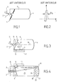
- the Figure 2 is the elementary transfer function for an input-output fiber pair of the device of the Figure 1 .
- the Figure 3 is a multiplexer-demultiplexer according to the invention.
- the Figure 4 is a multiplexer-demultiplexer, according to the invention, temperature stabilized.
- the figures represent the optical components of the device of the invention, independently of the mechanical structures that carry them and ensure their respective positions. These mechanical structures can take many forms and are accessible to those skilled in the art.
- optical fibers as input and output means of the multiplexer-demultiplexer. It is, however, well known that there are emitting components (diodes, arrays or diode arrays) and receiver components (CCDs - Charge Coupled Devices - CCD arrays or matrices) whose active elements are small, of the same order of magnitude that the hearts of fibers, from a few microns to a few tens of microns, and regularly distributed, whose characteristics make them compatible with the fibers. In some applications, such components may replace the fibers at the input or output of the multiplexer-demultiplexer of the invention and be placed in place of the ends of said fibers directly at the spectral focal point. Such components are therefore equivalent to the fibers in the definition of the invention.
- the multiplexer-demultiplexer shown on the Figure 1 comprises a dispersive system constituted by a network 1, an input fiber 2 which supplies the device with a multiplexed luminous flux and an output fiber comb 3 which provides differentiated fluxes for each of the wavelengths.
- the ends of these fibers 3, in variable number, are placed in the center of the network 1, itself approximately at the focus of a reflective optical system 4.
- the space 5 located between the network 1 and the mirror 4 can receive different components optics allowing according to the needs, to improve the properties of the system.
- the network 1 can be holographic or engraved.
- the elementary transfer function defining the wavelength bandwidth for an input fiber-output fiber pair, corresponding to a wavelength ⁇ o has the shape shown in FIG. Figure 2 . It is centered on the wavelength ⁇ o and its width at half height is ⁇ o . This width at half height depends on all the geometric and optical characteristics of the device.
- Crosstalk is the effect produced by a risk of overlap of the transfer functions, respectively associated with two wavelengths ⁇ 1 and ⁇ 2 close to each other.
- the multiplexer-demultiplexer of the invention is more particularly presented on the Figure 3 .
- the input fiber 2 and the output fibers 3 have their ends placed at the focus of the spherical mirror 4.
- the luminous flux emitted by the input fiber 2 is transformed by the mirror 4 into a parallel flow and is reflected. by the mirror 8 inclined at an angle with respect to the axis 10 input-output of the luminous flux.
- This parallel beam is thus reflected by the mirror 8 into a secondary parallel beam of axis 12.
- the diffraction grating 7 carried by a network support 9 is applied against one of the plane lateral faces 13 of the multiplexer, the normal to the plane the network being comprised in the plane formed by the input-output axis 10 and the normal to the mirror 8.
- the secondary beam 12 forms an angle ⁇ with the normal to the network (Littrow angle).
- the mirror 8 is pierced with an opening central 11. This central opening of small dimension thus allows the transmission of light flows from or to the fibers without significantly disturbing the reflection of the parallel beam reflected by the spherical mirror 4.
- the light beam incident on the grating 7 is diffracted, reflected back by the mirror 8 and also back-reflected by the spherical mirror 4 towards the output fibers 3, as a function of the wavelength of the luminous flux.
- the body 6 of the multiplexer-demultiplexer may be designed to provide thermal correction.
- the implementation of a silica element 6 LF5 provides a very good stability between -20 ° C and + 60 ° C.
- the network 7 is therefore according to the invention, placed on a side plane side of the multiplexer. It can be attached to it after being molded on a support 9.
- the support 9 is then glued to the face 13 of the multiplexer-demultiplexer or fixed by elastic junctions preferably at three points.
- the network is then formed in a conventional manner from a matrix giving its shape to a resin previously deposited on the support or side face 13.
- the network thus formed with the precautions of use allowing the demolding in good conditions is then covered with a reflective treatment and then protected by a varnish.
- the multiplexer-demultiplexer shown on the Figure 4 comprises a fiber holder 15 fixing the input fiber 2 and the output fibers 3.
- a dispersive element 16, here a network is carried by a network support 17.
- the fiber carrier 15 and the network support 17 are in contact via an interface 18.
- the mirror 19 reflects the radiation it receives, it is integral with a doublet composed of two elements 20 and 21 associated by an interface 22.
- the diffracted fluxes are again reflected by the mirror 19 and, depending on their wavelength, coupled to the output fibers 3.
- the indices and radii of curvature of the doublet 20, 21 are determined in such a way that it corrects the geometric and chromatic aberrations of the assembly.
- the space 25 between the diffractive element 16 and the first diopter 26 of the reflector doublet is occupied by air or a gas, or vacuum.
- the properties of the reflective achromatic doublet are preferably as follows:
- the first element 21 carrying the reflecting mirror 19 is made of a glass known under the reference BaF52, its central thickness is 7.66 mm, the curvature of its face carrying the mirror is 401.56 mm and the curvature of its second side is 748.90 mm.
- the second element 20 of this doublet is made of a glass known as PSK3, the curvature of its second face is 217.77 mm, the distance between the interface 22 and the reflecting mirror is 271.6 mm.
- the material of the element 17 carrying the network is silica.
- the distance from the face 28 to the end of the filter holder is 21.49 mm.
- the average distance between the interfaces 23 and 18 is 22 mm and the distance between 23 and the reflecting mirror is 271.1 mm.
- the assembly between the two sub-assemblies, the one carrying the network and the one carrying the reflector doublet, is carried out using a tube with square section of silica or other material with a low coefficient of expansion on which are based the faces 16 and 26.
Landscapes
- Physics & Mathematics (AREA)
- General Physics & Mathematics (AREA)
- Optics & Photonics (AREA)
- Engineering & Computer Science (AREA)
- Microelectronics & Electronic Packaging (AREA)
- Diffracting Gratings Or Hologram Optical Elements (AREA)
- Optical Communication System (AREA)
- Optical Couplings Of Light Guides (AREA)
Claims (9)
- Wellenlängen-Multiplexer-Demultiplexer mit Lichtleitfasern mit einer optischen Achse (10), Folgendes aufweisend:- ein ebenes Beugungsgitter (7) mit einer Streuungsebene,- mindestens eine Eingangsfaser (2) mit einer Ausgangsseite,- mindestens eine Ausgangsfaser (3) mit einer Eingangsseite und- Mittel zur optischen Konjugation der Ausgangsseite der Eingangsfaser (2) mit der Eingangsseite der Ausgangsfaser (3), wobei die Mittel zur optischen Konjugation reflektierende Mittel aufweisen, die das Funktionieren des Gitters in Littrow-Konfiguration sicherstellen und das Rückfalten der optischen Achse sicherstellen,Multiplexer-Demultiplexer dadurch gekennzeichnet,
dass die Mittel zur optischen Konjugation eine Eingangs- und Ausgangsachse haben, in deren Nähe sich die Ausgangsseite der Eingangsfaser und die Eingangsseite der Ausgangsfaser befinden,
dass die reflektierenden Mittel Folgendes aufweisen:- einen ersten Spiegel (4, 19), dessen Brennpunkt auf dem Niveau des Endes der Eingangsfasern (2) und Ausgangsfasern (3) plaziert ist, der einen divergenten Lichtstrom in einen parallelen Lichtstrom umwandelt,- einen zweiten Spiegel (8), der auf der Eingangs- und Ausgangsachse der Mittel zur optischen Konjugation zwischen dem Ende der Fasern und dem ersten Spiegel (4, 19) platziert ist, der in Bezug auf die Achse geneigt ist und eine zentrale Öffnung aufweist, die das Durchgehen eines auf diese Achse gelenkten Lichtstroms erlaubt, und dass die Ebene des Beugungsgitters parallel zu der Eingangs- und Ausgangsachse der Mittel zur optischen Konjugation ist. - Wellenlängen-Multiplexer-Demultiplexer mit Lichtleitfasern nach Anspruch 1, dadurch gekennzeichnet, dass der erste Spiegel (4, 19) ein sphärischer Spiegel ist.
- Wellenlängen-Multiplexer-Demultiplexer mit Lichtleitfasern nach Anspruch 2, dadurch gekennzeichnet, dass der sphärische Spiegel (19) fest mit einem Dublett verbunden ist, das aus zwei Elementen (20, 21) in Berührung mit einer Schnittstelle (22) besteht und die Korrektur der geometrischen und chromatischen Aberrationen sicherstellt .
- Wellenlängen-Multiplexer-Demultiplexer mit Lichtleitfasern nach einem der Ansprüche 1 bis 3, dadurch gekennzeichnet, dass der Multiplexer-Demultiplexer aus einer Einheit optischer zusammengehörender Elemente besteht, wobei das Beugungsgitter auf einer Seitenfläche eines Elements befestigt ist, das eine Achse parallel zu der Eingangs- und Ausgangsachse der optischen Konjugationsmittel hat.
- Wellenlängen-Multiplexer-Demultiplexer mit Lichtleitefasern nach Anspruch 4, dadurch gekennzeichnet, dass die optischen Elemente beklebt sind.
- Wellenlängen-Multiplexer-Demultiplexer mit Lichtleitfasern nach Anspruch 4, dadurch gekennzeichnet, dass das Beugungsgitter auf den Elemente mit elastischen Verbindungen befestigt ist.
- Wellenlängen-Multiplexer-Demultiplexer mit Lichtleitfasern nach einem der Anspruche 1 bis 3, dadurch gekennzeichnet, dass der Multiplexer-Demultiplexer aus einer Einheit zusammengehörender optischer Elemente besteht, und dass das Beugungsgitter direkt auf einer der Seitenflächen eines dieser optischen Elemente ausgebildet ist.
- Wellenlängen-Multiplexer-Demultiplexer mit Lichtleitfasern nach einem der Ansprüche 1 bis 7, dadurch gekennzeichnet, dass das Beugungsgitter auf einem Träger getragen wird, der gedehnt werden kann, so dass der Schritt des Gitters variiert.
- Wellenlängen-Multiplexer-Demultiplexer mit Lichtleitfasern nach Anspruch 8, dadurch gekennzeichnet, dass der Träger des Gitters dielektrisch ist.
Applications Claiming Priority (2)
| Application Number | Priority Date | Filing Date | Title |
|---|---|---|---|
| FR9807046 | 1998-06-04 | ||
| FR9807046A FR2779535B1 (fr) | 1998-06-04 | 1998-06-04 | Multiplexeur compact |
Publications (2)
| Publication Number | Publication Date |
|---|---|
| EP0962792A1 EP0962792A1 (de) | 1999-12-08 |
| EP0962792B1 true EP0962792B1 (de) | 2008-12-10 |
Family
ID=9527026
Family Applications (1)
| Application Number | Title | Priority Date | Filing Date |
|---|---|---|---|
| EP99401223A Expired - Lifetime EP0962792B1 (de) | 1998-06-04 | 1999-05-20 | Kompakter Multiplexer |
Country Status (5)
| Country | Link |
|---|---|
| US (1) | US6263134B1 (de) |
| EP (1) | EP0962792B1 (de) |
| JP (1) | JP4711474B2 (de) |
| DE (1) | DE69940040D1 (de) |
| FR (1) | FR2779535B1 (de) |
Families Citing this family (13)
| Publication number | Priority date | Publication date | Assignee | Title |
|---|---|---|---|---|
| US6343169B1 (en) * | 1999-02-25 | 2002-01-29 | Lightchip, Inc. | Ultra-dense wavelength division multiplexing/demultiplexing device |
| JP3677593B2 (ja) * | 1999-03-30 | 2005-08-03 | 日本板硝子株式会社 | 光分波器及びその調心組立方法 |
| US6556297B1 (en) * | 2000-06-02 | 2003-04-29 | Digital Lightwave, Inc. | Athermalization and pressure desensitization of diffraction grating based spectrometer devices |
| US6343170B1 (en) * | 2000-06-27 | 2002-01-29 | Optichrom Inc. | Optical spectrum analyzer |
| US6421479B1 (en) * | 2000-10-31 | 2002-07-16 | Zolo Technologies, Inc. | Apparatus and method facilitating optical alignment of a bulk optical multiplexer/demultiplexer |
| US6597452B1 (en) * | 2000-11-17 | 2003-07-22 | Jobin Yvon, Inc. | Compact littrow-type scanning spectrometer |
| JP2003107278A (ja) * | 2001-09-28 | 2003-04-09 | Nippon Sheet Glass Co Ltd | 光モジュール及び光モジュールの作製方法 |
| US7203421B2 (en) * | 2001-09-28 | 2007-04-10 | Optical Research Associates | Littrow grating based OADM |
| US6879749B2 (en) * | 2001-11-27 | 2005-04-12 | Ec-Optics Technology Inc. | System and method for multiplexing and demultiplexing optical signals using diffraction gratings |
| KR100445905B1 (ko) * | 2001-12-13 | 2004-08-25 | 한국전자통신연구원 | 다중파장 광 전송 시스템에서 광 신호 성능 측정 장치 및그 방법 |
| US7058251B2 (en) * | 2002-06-12 | 2006-06-06 | Optical Research Associates | Wavelength selective optical switch |
| EP2083298B1 (de) * | 2008-01-23 | 2017-05-10 | Yenista Optics | Optische Vorrichtung mit einem kompakten Dispersionssystem |
| FI20106141A0 (fi) | 2010-11-01 | 2010-11-01 | Specim Spectral Imaging Oy Ltd | Kuvantava spektrometri |
Family Cites Families (19)
| Publication number | Priority date | Publication date | Assignee | Title |
|---|---|---|---|---|
| JPS55105211A (en) * | 1979-02-07 | 1980-08-12 | Matsushita Electric Ind Co Ltd | Photo branching and coupling device |
| FR2519148B1 (fr) * | 1981-12-24 | 1985-09-13 | Instruments Sa | Selecteur de longueurs d'ondes |
| JPS576806A (en) * | 1980-06-13 | 1982-01-13 | Mitsubishi Electric Corp | Optical branching filter |
| US4387955A (en) * | 1981-02-03 | 1983-06-14 | The United States Of America As Represented By The Secretary Of The Air Force | Holographic reflective grating multiplexer/demultiplexer |
| US4559500A (en) * | 1981-10-09 | 1985-12-17 | California Institute Of Technology | Mirror-grating tuning arrangement for high resolution lasers |
| FR2579333B1 (fr) * | 1985-03-20 | 1987-07-03 | Instruments Sa | Multiplexeur-demultiplexeur de longueurs d'ondes corrige des aberrations geometriques et chromatiques |
| JPH0638595B2 (ja) * | 1985-12-17 | 1994-05-18 | 松下電器産業株式会社 | 波長多重光通信用光源 |
| JPH0797298B2 (ja) * | 1987-11-30 | 1995-10-18 | 動力炉・核燃料開発事業団 | ナトリウム循環系統の温度制御装置 |
| US5245404A (en) * | 1990-10-18 | 1993-09-14 | Physical Optics Corportion | Raman sensor |
| US5206920A (en) * | 1991-02-01 | 1993-04-27 | Siemens Aktiengesellschaft | Integrated optical arrangement for demultiplexing a plurality of different wavelength channels and the method of manufacture |
| JP2600507B2 (ja) * | 1991-03-12 | 1997-04-16 | 松下電器産業株式会社 | 光合分波器 |
| US5457573A (en) * | 1993-03-10 | 1995-10-10 | Matsushita Electric Industrial Co., Ltd. | Diffraction element and an optical multiplexing/demultiplexing device incorporating the same |
| US5917625A (en) * | 1993-09-09 | 1999-06-29 | Kabushiki Kaisha Toshiba | High resolution optical multiplexing and demultiplexing device in optical communication system |
| JP3153406B2 (ja) * | 1994-03-03 | 2001-04-09 | 松下電器産業株式会社 | 光回路及びそれを用いた光伝送システム |
| FR2738432B1 (fr) * | 1995-09-01 | 1997-09-26 | Hamel Andre | Composant optique adapte a la surveillance d'une liaison multilongueur d'onde et multiplexeur a insertion-extraction utilisant ce composant, application aux reseaux optiques |
| EP0848839A4 (de) * | 1996-07-02 | 1999-05-19 | Corning Inc | Beugungsgitter mit reduzierter polarisationsempfindlichkeit |
| US6097859A (en) * | 1998-02-12 | 2000-08-01 | The Regents Of The University Of California | Multi-wavelength cross-connect optical switch |
| US6084695A (en) * | 1997-02-14 | 2000-07-04 | Photonetics | Optical fiber wavelength multiplexer and demutiplexer |
| US6011884A (en) * | 1997-12-13 | 2000-01-04 | Lightchip, Inc. | Integrated bi-directional axial gradient refractive index/diffraction grating wavelength division multiplexer |
-
1998
- 1998-06-04 FR FR9807046A patent/FR2779535B1/fr not_active Expired - Fee Related
-
1999
- 1999-05-20 DE DE69940040T patent/DE69940040D1/de not_active Expired - Lifetime
- 1999-05-20 EP EP99401223A patent/EP0962792B1/de not_active Expired - Lifetime
- 1999-05-25 US US09/317,899 patent/US6263134B1/en not_active Expired - Lifetime
- 1999-06-04 JP JP15729299A patent/JP4711474B2/ja not_active Expired - Fee Related
Also Published As
| Publication number | Publication date |
|---|---|
| US6263134B1 (en) | 2001-07-17 |
| EP0962792A1 (de) | 1999-12-08 |
| FR2779535B1 (fr) | 2000-09-01 |
| JP4711474B2 (ja) | 2011-06-29 |
| FR2779535A1 (fr) | 1999-12-10 |
| JP2000028847A (ja) | 2000-01-28 |
| DE69940040D1 (de) | 2009-01-22 |
Similar Documents
| Publication | Publication Date | Title |
|---|---|---|
| EP0275795B1 (de) | Wellenlängen-Multiplexer/-Demultiplexer mit einem elliptischen Konkavgitter und dessen Anwendung in der integrierten Optik | |
| EP0138698B1 (de) | Optischer Wellenlängen-Multiplexer-Demultiplexer für bidirektionale Verbindung | |
| EP0562953B1 (de) | Durch Rotation abstimmbares Fabry-Perot-Interferometor enthaltendes optisches Filter | |
| EP0962792B1 (de) | Kompakter Multiplexer | |
| EP0196948B1 (de) | Umkehrbare Demultiplexeinrichtung von einer Mehrzahl von Lichtsignalen in integrierter Optik | |
| EP0721118B1 (de) | Verfahren zur Herstellung eines Gitterelements in einer optischen Faser | |
| EP1006628B1 (de) | Mehrwellenlängen-Quelle | |
| EP0121482A1 (de) | Wellenlängenmultiplexer/-demultiplexer und Verfahren zur Herstellung einer solchen Vorrichtung | |
| FR2758675A1 (fr) | Multiplexeur-demultiplexeur en longueurs d'onde | |
| FR2689349A1 (fr) | Multiplexeur en longueur d'onde pour système optique intégré. | |
| EP0887672A1 (de) | Faseroptischer Wellenlängen-Multiplexer-Demultiplexer | |
| FR2560470A1 (fr) | Multiplexeur-demultiplexeur optique de longueurs d'onde utilisant des fibres optiques | |
| FR2743234A1 (fr) | Demultiplexeur de longueurs d'onde | |
| FR2655430A1 (fr) | Coupeur optique et systeme informatique a processeurs repartis. | |
| EP1030195B1 (de) | Selbstausrichtendes retroreflektierendes optisches System zur Wellenlängenfilterung und dessen Verwendung in Monochromatoren und Lasern | |
| EP0037787B1 (de) | Monochromator | |
| EP0884615B1 (de) | Faseroptischer Wellenlängen-Multiplexer-Demultiplexer | |
| EP1000328A1 (de) | Mikromonochromator und verfahren für dessen herstellung | |
| FR2661513A3 (fr) | Aiguillage optique a fibres. | |
| EP1433006B1 (de) | Optische komponente für die spektrale separation von licht verschiedener wellenlängen | |
| FR2794858A1 (fr) | Dispositif analyseur de spectre optique a reseau de diffraction en optique integree | |
| EP1546770B1 (de) | Optische filterkomponente mit flacher oberseite | |
| FR2816062A1 (fr) | Filtre optique, son procede de fabrication par dopage ionique et son utilisation pour un systeme multiplex | |
| FR2875018A1 (fr) | Dispositif de combinaison de faisceaux laser ayant des longueurs d'onde differentes | |
| FR2815417A1 (fr) | Filtre optique, son procede de fabrication et son utilisation pour un systeme multiplex |
Legal Events
| Date | Code | Title | Description |
|---|---|---|---|
| PUAI | Public reference made under article 153(3) epc to a published international application that has entered the european phase |
Free format text: ORIGINAL CODE: 0009012 |
|
| AK | Designated contracting states |
Kind code of ref document: A1 Designated state(s): DE FR GB |
|
| AX | Request for extension of the european patent |
Free format text: AL;LT;LV;MK;RO;SI |
|
| 17P | Request for examination filed |
Effective date: 19991230 |
|
| AKX | Designation fees paid |
Free format text: DE FR GB |
|
| RAP1 | Party data changed (applicant data changed or rights of an application transferred) |
Owner name: HIGHWAVE OPTICAL TECHNOLOGIES |
|
| RAP1 | Party data changed (applicant data changed or rights of an application transferred) |
Owner name: YENISTA OPTICS SA |
|
| 17Q | First examination report despatched |
Effective date: 20060706 |
|
| GRAP | Despatch of communication of intention to grant a patent |
Free format text: ORIGINAL CODE: EPIDOSNIGR1 |
|
| GRAS | Grant fee paid |
Free format text: ORIGINAL CODE: EPIDOSNIGR3 |
|
| GRAA | (expected) grant |
Free format text: ORIGINAL CODE: 0009210 |
|
| AK | Designated contracting states |
Kind code of ref document: B1 Designated state(s): DE FR GB |
|
| REG | Reference to a national code |
Ref country code: GB Ref legal event code: FG4D Free format text: NOT ENGLISH |
|
| REF | Corresponds to: |
Ref document number: 69940040 Country of ref document: DE Date of ref document: 20090122 Kind code of ref document: P |
|
| PLBE | No opposition filed within time limit |
Free format text: ORIGINAL CODE: 0009261 |
|
| STAA | Information on the status of an ep patent application or granted ep patent |
Free format text: STATUS: NO OPPOSITION FILED WITHIN TIME LIMIT |
|
| 26N | No opposition filed |
Effective date: 20090911 |
|
| REG | Reference to a national code |
Ref country code: FR Ref legal event code: PLFP Year of fee payment: 18 |
|
| REG | Reference to a national code |
Ref country code: FR Ref legal event code: PLFP Year of fee payment: 19 |
|
| REG | Reference to a national code |
Ref country code: FR Ref legal event code: PLFP Year of fee payment: 20 |
|
| PGFP | Annual fee paid to national office [announced via postgrant information from national office to epo] |
Ref country code: DE Payment date: 20180430 Year of fee payment: 20 |
|
| PGFP | Annual fee paid to national office [announced via postgrant information from national office to epo] |
Ref country code: FR Payment date: 20180426 Year of fee payment: 20 |
|
| PGFP | Annual fee paid to national office [announced via postgrant information from national office to epo] |
Ref country code: GB Payment date: 20180427 Year of fee payment: 20 |
|
| REG | Reference to a national code |
Ref country code: DE Ref legal event code: R071 Ref document number: 69940040 Country of ref document: DE |
|
| REG | Reference to a national code |
Ref country code: GB Ref legal event code: PE20 Expiry date: 20190519 |
|
| PG25 | Lapsed in a contracting state [announced via postgrant information from national office to epo] |
Ref country code: GB Free format text: LAPSE BECAUSE OF EXPIRATION OF PROTECTION Effective date: 20190519 |