EP0962848B1 - Vorrichtung zur Druckminderung - Google Patents
Vorrichtung zur Druckminderung Download PDFInfo
- Publication number
- EP0962848B1 EP0962848B1 EP99108825A EP99108825A EP0962848B1 EP 0962848 B1 EP0962848 B1 EP 0962848B1 EP 99108825 A EP99108825 A EP 99108825A EP 99108825 A EP99108825 A EP 99108825A EP 0962848 B1 EP0962848 B1 EP 0962848B1
- Authority
- EP
- European Patent Office
- Prior art keywords
- spring
- piston
- pressure
- force
- acted
- Prior art date
- Legal status (The legal status is an assumption and is not a legal conclusion. Google has not performed a legal analysis and makes no representation as to the accuracy of the status listed.)
- Expired - Lifetime
Links
- 239000003638 chemical reducing agent Substances 0.000 title abstract description 4
- 239000007789 gas Substances 0.000 claims description 6
- 238000002640 oxygen therapy Methods 0.000 claims description 3
- 238000007789 sealing Methods 0.000 description 5
- 238000010276 construction Methods 0.000 description 2
- 230000001419 dependent effect Effects 0.000 description 2
- 230000036316 preload Effects 0.000 description 2
- 230000003014 reinforcing effect Effects 0.000 description 2
- QVGXLLKOCUKJST-UHFFFAOYSA-N atomic oxygen Chemical compound [O] QVGXLLKOCUKJST-UHFFFAOYSA-N 0.000 description 1
- 238000005452 bending Methods 0.000 description 1
- 230000033228 biological regulation Effects 0.000 description 1
- 210000000748 cardiovascular system Anatomy 0.000 description 1
- 230000007423 decrease Effects 0.000 description 1
- 201000010099 disease Diseases 0.000 description 1
- 208000037265 diseases, disorders, signs and symptoms Diseases 0.000 description 1
- 230000000694 effects Effects 0.000 description 1
- 230000002349 favourable effect Effects 0.000 description 1
- 238000004519 manufacturing process Methods 0.000 description 1
- 230000000474 nursing effect Effects 0.000 description 1
- 239000001301 oxygen Substances 0.000 description 1
- 229910052760 oxygen Inorganic materials 0.000 description 1
- 210000002345 respiratory system Anatomy 0.000 description 1
- 230000008454 sleep-wake cycle Effects 0.000 description 1
- 238000001228 spectrum Methods 0.000 description 1
- 238000002560 therapeutic procedure Methods 0.000 description 1
- 238000003466 welding Methods 0.000 description 1
Images


Classifications
-
- A—HUMAN NECESSITIES
- A62—LIFE-SAVING; FIRE-FIGHTING
- A62B—DEVICES, APPARATUS OR METHODS FOR LIFE-SAVING
- A62B9/00—Component parts for respiratory or breathing apparatus
- A62B9/02—Valves
-
- G—PHYSICS
- G05—CONTROLLING; REGULATING
- G05D—SYSTEMS FOR CONTROLLING OR REGULATING NON-ELECTRIC VARIABLES
- G05D16/00—Control of fluid pressure
- G05D16/04—Control of fluid pressure without auxiliary power
- G05D16/10—Control of fluid pressure without auxiliary power the sensing element being a piston or plunger
Definitions
- the invention relates to a device for reducing pressure for flowing gaseous media that have at least one gas inlet and has at least one gas outlet and at the inside a piston is arranged in a flow channel is loaded by a spring with a clamping force that the Pushes the piston away from a base, in the area of which Flow opening that can be closed by the piston is arranged and in which the piston has an area of action, which can be acted upon by the pressure-reduced medium and which is arranged facing away from a pressure surface for the spring is, and in which the piston is acted upon by a second spring which is provided with an adjusting element which a bias between the second spring and the piston purports
- Such devices are commonly used as piston pressure reducers referred to and can be used in a wide range of applications be used. Typical fields of application are in the area of ventilators and gas bottles from Welding equipment. A typical arrangement is in U.S. Patent 5 662 100.
- the typical mode of operation is that Flow opening through the gaseous medium up to the area of the action surface of the piston is guided and generates a force here, that of the force of the spring is opposite.
- the spring first pushes the piston off the flow opening away, so that a relatively large gas passage with a correspondingly high pressure build-up in the area the area of action is made possible.
- This pressure creates however, due to the relatively large dimensioning of the area of action a back pressure that leads to an approximation of the Piston leads to the flow opening.
- Dependent on on the dimensioning of the spring force and the size of the A balance of forces can be predetermined in this way be that a selectable reduced pressure is reached becomes.
- the respective flow volume is inevitable due to the selected component dimensioning and is not variable without design changes. At one time The chosen design implementation is the volume flow no longer changeable.
- EP-A-0 903 533 also describes a valve for reducing pressure described in the two on a positioning piston Act springs.
- the springs are relative to a direction of movement arranged in a row. An application of the springs as well as a power development of the springs only possible together.
- the object of the present invention is a device to construct the type mentioned in the introduction such that in addition to specify the output pressure also the Volume flow is adjustable.
- a middle part for acting on the second spring essentially extends along a longitudinal axis of the first spring and that the second spring is relative to the first spring is arranged such that the second spring one on the Piston biasing force of the first spring of a correction force for the defined specification of an equilibrium point of the pressure regulator overlaid.
- a typical area of application is developed in that intended for use in the area of a ventilator is.
- the second spring be a smaller one Has spring constant than the first spring.
- Fine control is particularly advantageous if if the devices are in different patients be used. Depending on the individual The entire spectrum can meet requirements of the therapeutically useful dosages optimally covered become.
- oxygen supply to patients possible to the intra-individual fluctuations take into account that are caused by the fact that the therapeutically required dose of each existing different physical stresses is dependent. In particular, it is also possible Sleep-wake rhythm when determining the dosage to consider.
- a respective working point can be set be that the second spring with an adjuster is connected to the specification of a pretensioning force.
- the second spring in an interior the piston is arranged.
- the adjusting element is a manually operable Has cap.
- a favorable line of force in the housing area is supported by the fact that there is a central part for loading the second spring substantially along one Longitudinal axis of the first spring extends.
- a geometrically short design can be supported by that the piston from the first spring and the second spring with power deployments in opposite directions Directions is applied.
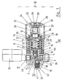
- a housing (1) has an inlet (2) into which the gaseous medium can enter. Via inner connection channels (3) the gaseous feed arrives Medium that typically has a feed pressure of can have about 200 bar, in the range of Flow opening (4).
- the flow opening (4) is typically in the area of a cone Elevation (5) of a base (6) arranged, the areas limited a flow channel (7).
- Within a piston (8) is arranged in the flow channel (7), which is displaceable in the direction of a longitudinal axis (9) is guided in the flow channel (7).
- the piston (8) has a sealing element (10), for example as a block made of plastic can be, which is embedded in the piston (8).
- the piston (8) has a slightly smaller outside diameter as an inner diameter of the flow channel (7) is. This will separate the piston (8) and the wall of the flow channel (7) an annular channel provided. Basically it is also conceivable, the piston (8) with a to the inner diameter of the flow channel (7) adapted dimensioning to be provided and to provide channels in the area of the piston (8), which extend in the direction of the longitudinal axis (9). These channels can be used, for example, as external profiles of the piston (8).
- the piston (8) Due to the dimensioning of the piston (8) becomes a flow passage to a transverse channel (11) provided, which in turn in a central channel (12) which essentially runs along the Longitudinal axis (9) extends through the piston (8).
- the central channel (12) opens into the area of the transverse channel (11) facing expansion into an interior (13) of the piston (8).
- the interior (13) is from a piston wall (14) limited in the area of their the expansion facing away from the central channel (12) laterally projecting ring flange opens out.
- the ring flange (15) is acted upon by a spring (16), those facing away from the ring flange (15) End supported on the housing (1).
- a central axis the spring (16) essentially coincides with the longitudinal axis (9) of the piston (8) together.
- the spring (16) surrounds it spiral the piston (8).
- the ring flange (15) is in the direction of the longitudinal axis (9) guided in translation in the housing (1).
- the Ring flange (15) has in the region of its spring (16) facing away from an action surface (17), which together with the housing (1) a back pressure chamber (18) bounded by a channel (19) with the interior (13) is connected.
- the ring flange (15) is from a seal (20) sealed against the housing (1).
- the piston (8) is also within the flow channel (7) from a seal (21) opposite the Sealed housing (1).
- the seals (20, 21) can for example be designed as O-rings.
- the piston (8) in the area of a Base surface (23) of the interior (13) is applied.
- the Base area (23) surrounds the mouth of the central channel (12) into the interior (13).
- the adjusting element (24) from a cap (25) with an internal thread guided on an external thread of the housing (1) is.
- the cap (25) acts on a central part (26) a counter element (27) which acts on the second spring (22).
- the counter element (27) can be used as a disc be formed with a central passage.
- the cap (25) is provided with a trough (28), in which protrudes the middle part (26) with a shaft (29).
- the shaft (29) has an external thread that is acted upon by a mother (30). About an adjustment the nut (30) can be preloaded for the second spring (22) can be defined.
- the trough (28) is closed by a cover (31).
- a reinforcing element (33) let in, for example similar to a Washer can be formed.
- the housing (1) forms a guide surrounding the central part (26), relative to that of the central part (26) in an environment the back pressure chamber (18) sealed by a seal (34) is.
- the seal (34) can be designed as an O-ring his.
- the pressure in the area of the inlet (2) becomes indicated by an input manometer (35).
- the essential Proportion of that passing through the flow opening (4) pressure-reduced medium becomes the outlet (36) headed.
- the pressure is limited by a Pressure relief valve (37) having a ball (38), the by a spring (39) against an overflow opening (40) the outlet (36) is pressed.
- a bias of the Spring (39) can be predetermined by a spring cap (41).
- the Spring cap (41) is provided with an outflow opening (42), a derivative of the possibly emerging to enable gaseous medium.
- the housing (1) is provided in the area of the various To provide flow channels with a housing block (43) and in the area of action of the spring (16) on the Housing block (43) an additional reinforcing element (44) to be arranged.
- FIG Assembly of the output manometer (45) is the exit manometer (45) with a shaft (52) in a bore (53) of the housing block (43) used.
- a sealing element (54) and a Pressure disc (55) are used for sealing.
Landscapes
- Health & Medical Sciences (AREA)
- Physics & Mathematics (AREA)
- Pulmonology (AREA)
- Business, Economics & Management (AREA)
- Automation & Control Theory (AREA)
- Engineering & Computer Science (AREA)
- General Physics & Mathematics (AREA)
- General Health & Medical Sciences (AREA)
- Fluid Mechanics (AREA)
- Emergency Management (AREA)
- Control Of Fluid Pressure (AREA)
- Filling Or Discharging Of Gas Storage Vessels (AREA)
- Fluid-Damping Devices (AREA)
- Electrical Discharge Machining, Electrochemical Machining, And Combined Machining (AREA)
- Fluid-Pressure Circuits (AREA)
- Excavating Of Shafts Or Tunnels (AREA)
Description
- Figur 1:
- einen Querschnitt durch die Vorrichtung,
- Figur 2:
- eine Darstellung der Vorrichtung gemäß Blickrichtung II in Figur 1,
- Figur 3:
- eine vergrößerte Darstellung der Einzelheit III in Figur 1,
- Figur 4:
- eine vergrößerte Darstellung der Einzelheit IV in Figur 1,
- Figur 5:
- eine vergrößerte Darstellung der Einzelheit V in Figur 1, und
- Figur 6:
- eine vergrößerte Darstellung der Einzelheit VI in Figur 2.
Claims (9)
- Vorrichtung zur Druckminderung für strömende gasförmige Medien, die mindestens einen Gaseinlaß (2) sowie mindestens einen Gasauslaß (36) aufweist und bei der innerhalb eines Strömungskanals (7) ein Kolben (8) angeordnet ist, der von einer Feder (16) mit einer Spannkraft belastet ist, die den Kolben (8) von einer Grundfläche (6) wegdrückt, in deren Bereich eine vom Kolben (8) verschließbare Durchströmungsöffnung (4) angeordnet ist und bei der der Kolben (8) eine Einwirkungsfläche aufweist, die von dem druckgeminderten Medium beaufschlagbar ist und die einer Andruckfläche für die Feder abgewandt angeordnet ist, sowie bei der der Kolben (8) von einer zweiten Feder (16) beaufschlagt ist, die mit einem Einstellelement (24) versehen ist, das eine Vorspannung zwischen der zweiten Feder (22) und dem Kolben (8) vorgibt, dadurch gekennzeichnet, daß sich ein Mittelteil (26) zur Beaufschlagung der zweiten Feder (22) im wesentlichen entlang einer Längsachse (9) der ersten Feder (16) erstreckt und daß die zweite Feder (22) relativ zur ersten Feder (16) derart angeordnet ist, daß die zweite Feder (22) einer auf den Kolben (8) einwirkenden Vorspannkraft der ersten Feder (16) eine Korrekturkraft zur definierten Vorgabe eines Gleichgewichtspunktes des Druckreglers überlagert.
- Vorrichtung nach Anspruch 1, dadurch gekennzeichnet, daß eine Verwendung im Bereich eines Beatmungsgerätes vorgesehen ist.
- Vorrichtung nach Anspruch 1 oder 2, dadurch gekennzeichnet, daß eine Verwendung im Bereich eines Gerätes zur Durchführung einer Sauerstofftherapie vorgesehen ist.
- Vorrichtung nach einem der Ansprüche 1 bis 3, dadurch gekennzeichnet, daß die erste Feder (16) und die zweite Feder (22) koaxial zueinander angeordnet sind.
- Vorrichtung nach einem der Ansprüche 1 bis 4, dadurch gekennzeichnet, daß die zweite Feder (22) eine kleinere Federkonstante als die erste Feder (16) aufweist.
- Vorrichtung nach einem der Ansprüche 1 bis 5, dadurch gekennzeichnet, daß die zweite Feder (22) mit einer Einstellvorrichtung zur Vorgabe einer VorSpannkraft verbunden ist.
- Vorrichtung nach einem der Ansprüche 1 bis 6, dadurch gekennzeichnet, daß die zweite Feder (22) in einem Innenraum (13) des Kolbens (8) angeordnet ist.
- Vorrichtung nach einem der Ansprüche 1 bis 7, dadurch gekennzeichnet, daß das Einstellelement (24) eine manuell betätigbare Kappe (25) aufweist.
- Vorrichtung nach einem der Ansprüche 1 bis 8, dadurch gekennzeichnet, daß der Kolben (8) von der ersten Feder (16) und der zweiten Feder (22) mit Kraftentfaltungen in einander entgegengesetzte Richtungen beaufschlagt ist.
Applications Claiming Priority (2)
| Application Number | Priority Date | Filing Date | Title |
|---|---|---|---|
| DE19825460 | 1998-06-06 | ||
| DE19825460A DE19825460C1 (de) | 1998-06-06 | 1998-06-06 | Vorrichtung zur Druckminderung |
Publications (3)
| Publication Number | Publication Date |
|---|---|
| EP0962848A2 EP0962848A2 (de) | 1999-12-08 |
| EP0962848A3 EP0962848A3 (de) | 2001-02-28 |
| EP0962848B1 true EP0962848B1 (de) | 2004-05-26 |
Family
ID=7870225
Family Applications (1)
| Application Number | Title | Priority Date | Filing Date |
|---|---|---|---|
| EP99108825A Expired - Lifetime EP0962848B1 (de) | 1998-06-06 | 1999-05-04 | Vorrichtung zur Druckminderung |
Country Status (4)
| Country | Link |
|---|---|
| EP (1) | EP0962848B1 (de) |
| AT (1) | ATE268019T1 (de) |
| DE (2) | DE19825460C1 (de) |
| ES (1) | ES2219950T3 (de) |
Families Citing this family (1)
| Publication number | Priority date | Publication date | Assignee | Title |
|---|---|---|---|---|
| LU92383B1 (en) | 2014-02-27 | 2015-08-28 | Luxembourg Patent Co Sa | Pressure reducer with cap-shaped movable chamber |
Family Cites Families (5)
| Publication number | Priority date | Publication date | Assignee | Title |
|---|---|---|---|---|
| US3211175A (en) * | 1961-04-03 | 1965-10-12 | Edward H Replogle | Valve regulator |
| US3818921A (en) * | 1972-09-15 | 1974-06-25 | Bendix Corp | Fluid flow throttling valve |
| EP0112765A1 (de) * | 1982-12-20 | 1984-07-04 | Litton Systems, Inc. | Druckminderungs- und Absperrventilkombination |
| US5662100A (en) * | 1996-01-11 | 1997-09-02 | Harsco Corporation | Eductive pressure regulator |
| JPH1194197A (ja) * | 1997-09-19 | 1999-04-09 | Neriki:Kk | ガスボンベ用バルブ装置およびそのバルブ装置の減圧弁 |
-
1998
- 1998-06-06 DE DE19825460A patent/DE19825460C1/de not_active Expired - Fee Related
-
1999
- 1999-05-04 ES ES99108825T patent/ES2219950T3/es not_active Expired - Lifetime
- 1999-05-04 EP EP99108825A patent/EP0962848B1/de not_active Expired - Lifetime
- 1999-05-04 DE DE59909562T patent/DE59909562D1/de not_active Expired - Lifetime
- 1999-05-04 AT AT99108825T patent/ATE268019T1/de active
Also Published As
| Publication number | Publication date |
|---|---|
| ATE268019T1 (de) | 2004-06-15 |
| DE59909562D1 (de) | 2004-07-01 |
| EP0962848A3 (de) | 2001-02-28 |
| ES2219950T3 (es) | 2004-12-01 |
| DE19825460C1 (de) | 1999-06-02 |
| EP0962848A2 (de) | 1999-12-08 |
Similar Documents
| Publication | Publication Date | Title |
|---|---|---|
| DE2145196C2 (de) | Absperrhahn mit einer den Betätigungszapfen umgreifenden Membrandichtung | |
| EP0678178B1 (de) | Sicherheitsschliessvorrichtung für gasleitungen | |
| DE69423879T2 (de) | Plattenventil | |
| DE3807166A1 (de) | Fluiddruck-reguliereinrichtung oder -stellglied | |
| WO2014198412A1 (de) | Druckausgleichseinsatz | |
| DE69623658T2 (de) | Durchflussmengesteuerungsöffnungen für eine thermostatische mischbatterie | |
| DE4437207C1 (de) | Gasverhältnisregelvorrichtung für Narkosegeräte | |
| EP1134467A1 (de) | Ventilanordnung einer Kälteanlage | |
| DE69219128T2 (de) | Regelventil | |
| EP2068222A2 (de) | Druckminderer | |
| DE19544901C2 (de) | Absperrvorrichtung für eine Fluidleitung, insbesondere Kugelhahn | |
| EP0962848A2 (de) | Vorrichtung zur Druckminderung | |
| DE60025338T2 (de) | Druckreduzierventil | |
| EP3353455A1 (de) | Rückschlagventil | |
| EP1212563B1 (de) | Einbauventil für einen gliederheizkörper | |
| DE202021101292U1 (de) | Druckmindereranordnung mit Anschlussteil zum Anschließen an eine Rohrleitung | |
| EP1411283B1 (de) | Hochdruckabdichtung für Gewindeeinsätze | |
| DE102021120670B3 (de) | Druckminderungsventil | |
| DE19712581A1 (de) | Absperrvorrichtung für eine Fluidleitung, insbesondere Kugelhahn | |
| DE10132001C2 (de) | Thermostatischer Regler zur Regelung der Durchflussmenge eines Fluids | |
| DE112006001873B4 (de) | Druckregler | |
| EP1475119B1 (de) | Vorrichtung zur Steuerung einer Gasströmung | |
| DE4101955C2 (de) | Sanitärarmatur | |
| EP1677039A1 (de) | Selbstarretierendes Durchflussgelenk | |
| WO2023161205A1 (de) | Zapfventil |
Legal Events
| Date | Code | Title | Description |
|---|---|---|---|
| PUAI | Public reference made under article 153(3) epc to a published international application that has entered the european phase |
Free format text: ORIGINAL CODE: 0009012 |
|
| AK | Designated contracting states |
Kind code of ref document: A2 Designated state(s): AT BE CH DE DK ES FR GB IT LI NL SE |
|
| AX | Request for extension of the european patent |
Free format text: AL;LT;LV;MK;RO;SI |
|
| PUAL | Search report despatched |
Free format text: ORIGINAL CODE: 0009013 |
|
| AK | Designated contracting states |
Kind code of ref document: A3 Designated state(s): AT BE CH CY DE DK ES FI FR GB GR IE IT LI LU MC NL PT SE |
|
| AX | Request for extension of the european patent |
Free format text: AL;LT;LV;MK;RO;SI |
|
| RIC1 | Information provided on ipc code assigned before grant |
Free format text: 7G 05D 16/10 A, 7A 62B 9/02 B |
|
| 17P | Request for examination filed |
Effective date: 20010210 |
|
| AKX | Designation fees paid |
Free format text: AT BE CH DE DK ES FR GB IT LI NL SE |
|
| 17Q | First examination report despatched |
Effective date: 20030108 |
|
| GRAP | Despatch of communication of intention to grant a patent |
Free format text: ORIGINAL CODE: EPIDOSNIGR1 |
|
| GRAS | Grant fee paid |
Free format text: ORIGINAL CODE: EPIDOSNIGR3 |
|
| GRAA | (expected) grant |
Free format text: ORIGINAL CODE: 0009210 |
|
| RAP1 | Party data changed (applicant data changed or rights of an application transferred) |
Owner name: WEINMANN GERAETE FUER MEDIZIN GMBH & CO. KG |
|
| AK | Designated contracting states |
Kind code of ref document: B1 Designated state(s): AT BE CH DE DK ES FR GB IT LI NL SE |
|
| PG25 | Lapsed in a contracting state [announced via postgrant information from national office to epo] |
Ref country code: NL Free format text: LAPSE BECAUSE OF FAILURE TO SUBMIT A TRANSLATION OF THE DESCRIPTION OR TO PAY THE FEE WITHIN THE PRESCRIBED TIME-LIMIT Effective date: 20040526 Ref country code: GB Free format text: LAPSE BECAUSE OF FAILURE TO SUBMIT A TRANSLATION OF THE DESCRIPTION OR TO PAY THE FEE WITHIN THE PRESCRIBED TIME-LIMIT Effective date: 20040526 Ref country code: FR Free format text: LAPSE BECAUSE OF NON-PAYMENT OF DUE FEES Effective date: 20040526 |
|
| REG | Reference to a national code |
Ref country code: GB Ref legal event code: FG4D Free format text: NOT ENGLISH |
|
| REG | Reference to a national code |
Ref country code: CH Ref legal event code: EP |
|
| REF | Corresponds to: |
Ref document number: 59909562 Country of ref document: DE Date of ref document: 20040701 Kind code of ref document: P |
|
| PG25 | Lapsed in a contracting state [announced via postgrant information from national office to epo] |
Ref country code: SE Free format text: LAPSE BECAUSE OF FAILURE TO SUBMIT A TRANSLATION OF THE DESCRIPTION OR TO PAY THE FEE WITHIN THE PRESCRIBED TIME-LIMIT Effective date: 20040826 Ref country code: DK Free format text: LAPSE BECAUSE OF FAILURE TO SUBMIT A TRANSLATION OF THE DESCRIPTION OR TO PAY THE FEE WITHIN THE PRESCRIBED TIME-LIMIT Effective date: 20040826 |
|
| GBV | Gb: ep patent (uk) treated as always having been void in accordance with gb section 77(7)/1977 [no translation filed] |
Effective date: 20040526 |
|
| NLV1 | Nl: lapsed or annulled due to failure to fulfill the requirements of art. 29p and 29m of the patents act | ||
| REG | Reference to a national code |
Ref country code: ES Ref legal event code: FG2A Ref document number: 2219950 Country of ref document: ES Kind code of ref document: T3 |
|
| PLBE | No opposition filed within time limit |
Free format text: ORIGINAL CODE: 0009261 |
|
| STAA | Information on the status of an ep patent application or granted ep patent |
Free format text: STATUS: NO OPPOSITION FILED WITHIN TIME LIMIT |
|
| 26N | No opposition filed |
Effective date: 20050301 |
|
| EN | Fr: translation not filed | ||
| PG25 | Lapsed in a contracting state [announced via postgrant information from national office to epo] |
Ref country code: LI Free format text: LAPSE BECAUSE OF NON-PAYMENT OF DUE FEES Effective date: 20050531 Ref country code: CH Free format text: LAPSE BECAUSE OF NON-PAYMENT OF DUE FEES Effective date: 20050531 Ref country code: BE Free format text: LAPSE BECAUSE OF NON-PAYMENT OF DUE FEES Effective date: 20050531 |
|
| BERE | Be: lapsed |
Owner name: *WEINMANN GERATE FUR MEDIZIN G.M.B.H. & CO. K.G. Effective date: 20050531 |
|
| REG | Reference to a national code |
Ref country code: CH Ref legal event code: PL |
|
| BERE | Be: lapsed |
Owner name: *WEINMANN GERATE FUR MEDIZIN G.M.B.H. & CO. K.G. Effective date: 20050531 |
|
| PGFP | Annual fee paid to national office [announced via postgrant information from national office to epo] |
Ref country code: IT Payment date: 20120522 Year of fee payment: 14 |
|
| PGFP | Annual fee paid to national office [announced via postgrant information from national office to epo] |
Ref country code: DE Payment date: 20120725 Year of fee payment: 14 Ref country code: ES Payment date: 20120525 Year of fee payment: 14 |
|
| PGFP | Annual fee paid to national office [announced via postgrant information from national office to epo] |
Ref country code: AT Payment date: 20120521 Year of fee payment: 14 |
|
| REG | Reference to a national code |
Ref country code: AT Ref legal event code: MM01 Ref document number: 268019 Country of ref document: AT Kind code of ref document: T Effective date: 20130531 |
|
| PG25 | Lapsed in a contracting state [announced via postgrant information from national office to epo] |
Ref country code: AT Free format text: LAPSE BECAUSE OF NON-PAYMENT OF DUE FEES Effective date: 20130531 Ref country code: DE Free format text: LAPSE BECAUSE OF NON-PAYMENT OF DUE FEES Effective date: 20131203 |
|
| REG | Reference to a national code |
Ref country code: DE Ref legal event code: R119 Ref document number: 59909562 Country of ref document: DE Effective date: 20131203 |
|
| PG25 | Lapsed in a contracting state [announced via postgrant information from national office to epo] |
Ref country code: IT Free format text: LAPSE BECAUSE OF NON-PAYMENT OF DUE FEES Effective date: 20130504 |
|
| REG | Reference to a national code |
Ref country code: ES Ref legal event code: FD2A Effective date: 20150710 |
|
| PG25 | Lapsed in a contracting state [announced via postgrant information from national office to epo] |
Ref country code: ES Free format text: LAPSE BECAUSE OF NON-PAYMENT OF DUE FEES Effective date: 20130505 |