EP0962879A2 - Dispositif pour l'évaluation de porteurs de données portables en forme de carte avec un canal de guidage - Google Patents
Dispositif pour l'évaluation de porteurs de données portables en forme de carte avec un canal de guidage Download PDFInfo
- Publication number
- EP0962879A2 EP0962879A2 EP99110574A EP99110574A EP0962879A2 EP 0962879 A2 EP0962879 A2 EP 0962879A2 EP 99110574 A EP99110574 A EP 99110574A EP 99110574 A EP99110574 A EP 99110574A EP 0962879 A2 EP0962879 A2 EP 0962879A2
- Authority
- EP
- European Patent Office
- Prior art keywords
- guide channel
- card
- sut
- data carrier
- shaped
- Prior art date
- Legal status (The legal status is an assumption and is not a legal conclusion. Google has not performed a legal analysis and makes no representation as to the accuracy of the status listed.)
- Withdrawn
Links
Images

Classifications
-
- G—PHYSICS
- G06—COMPUTING OR CALCULATING; COUNTING
- G06K—GRAPHICAL DATA READING; PRESENTATION OF DATA; RECORD CARRIERS; HANDLING RECORD CARRIERS
- G06K13/00—Conveying record carriers from one station to another, e.g. from stack to punching mechanism
- G06K13/02—Conveying record carriers from one station to another, e.g. from stack to punching mechanism the record carrier having longitudinal dimension comparable with transverse dimension, e.g. punched card
- G06K13/08—Feeding or discharging cards
- G06K13/0868—Feeding or discharging cards using an arrangement for keeping the feeding or insertion slot of the card station clean of dirt, or to avoid feeding of foreign or unwanted objects into the slot
- G06K13/0875—Feeding or discharging cards using an arrangement for keeping the feeding or insertion slot of the card station clean of dirt, or to avoid feeding of foreign or unwanted objects into the slot the arrangement comprising a shutter for blocking at least part of the card insertion slot
-
- G—PHYSICS
- G06—COMPUTING OR CALCULATING; COUNTING
- G06K—GRAPHICAL DATA READING; PRESENTATION OF DATA; RECORD CARRIERS; HANDLING RECORD CARRIERS
- G06K13/00—Conveying record carriers from one station to another, e.g. from stack to punching mechanism
- G06K13/02—Conveying record carriers from one station to another, e.g. from stack to punching mechanism the record carrier having longitudinal dimension comparable with transverse dimension, e.g. punched card
- G06K13/06—Guiding cards; Checking correct operation of card-conveying mechanisms
-
- G—PHYSICS
- G06—COMPUTING OR CALCULATING; COUNTING
- G06K—GRAPHICAL DATA READING; PRESENTATION OF DATA; RECORD CARRIERS; HANDLING RECORD CARRIERS
- G06K13/00—Conveying record carriers from one station to another, e.g. from stack to punching mechanism
- G06K13/02—Conveying record carriers from one station to another, e.g. from stack to punching mechanism the record carrier having longitudinal dimension comparable with transverse dimension, e.g. punched card
- G06K13/08—Feeding or discharging cards
- G06K13/0868—Feeding or discharging cards using an arrangement for keeping the feeding or insertion slot of the card station clean of dirt, or to avoid feeding of foreign or unwanted objects into the slot
- G06K13/0893—Feeding or discharging cards using an arrangement for keeping the feeding or insertion slot of the card station clean of dirt, or to avoid feeding of foreign or unwanted objects into the slot the arrangement comprising means for cleaning the card upon insertion
Definitions
- Payment is made for current public card phones of the phone calls made using magnetic or Chip cards, the value of which after a conversation telephone charges are reduced.
- An alternative Payment variant reads out on the magnet or Chip cards represent stored user data, afterwards an account of the user is charged accordingly.
- the utility model G 92 13 283.9 includes, for example Card reader with a guide channel for portable, card-shaped Data carrier emerges, which a locking device for Has closing the guide channel.
- One at rest Guide channel closing slide has two in the Edge areas of the guide channel arranged perpendicular to the slide, wedge-shaped approaches, being below the approaches an opening is provided in the slide for receiving the card is.
- wedge-shaped approaches being below the approaches an opening is provided in the slide for receiving the card is.
- the embossing area of a card is a width of approx. 20 mm and the card thickness in the embossing area a height of over 1.2 mm can be erroneous at this point or intentionally coins or coin-shaped objects in the card slot adapted to the embossing of the card or guide channel of the card reader. This leads to a blockage of the card reader, which the Failure of the devices or card phones. For Restoring the functionality of the card reader is a Maintenance process required.
- the invention has for its object the insertion of coin - shaped objects in card readers for reading out To prevent magnetic or chip cards.
- the task is starting from a data carrier evaluation device according to the Preamble of claim 1 by its characterizing Features resolved.
- a guide channel for portable, card-shaped Data carrier evaluation device having data carriers has a resilient closing device for closing of the guide channel and at least one with the locking device connected opening element on the closed State of the locking device in an edge region of the guide channel is arranged and one for the locking device in Insertion direction increasing ramp surface. Furthermore, there is a guide channel cover in front of the opening element intended. The locking device and the ramp surface are designed such that when the card-shaped data carrier the locking device from the Guide channel is pressed.
- the essential aspect of the invention Data carrier evaluation device exists in that the opening element and the guide channel cover are dimensioned such that the opening element is not of coin-shaped objects inserted into the guide channel is achieved.
- the main advantage of the data carrier evaluation device according to the invention consists in the simplest mechanical Wise and therefore with the least economic effort the insertion of non-card-shaped objects - like for example coin-shaped objects - in devices for evaluating chip or magnetic cards is prevented and therefore additional, with high economic effort associated maintenance operations can be saved.
- the functionality of the devices remains full received, thereby avoiding sales losses.
- a holding device V is arranged SUT locking device to prevent the insertion of coin-shaped objects in a guide channel of a data carrier evaluation device - not shown in FIG. 1 - shown sketchy.
- a base plate G On a base plate G is approximately U-shaped bending element or bent part B attached, a resilient, at the resiliently mounted end of the bent part B as running approximately obliquely over the bent part B.
- Locking surface designed locking device SUT - too referred to as shutter - is appropriate.
- the edges of the locking device SUT are approximate arranged at right angles to the locking device SUT and each have an inclined opening element R - in the following also referred to as a ramp - attached, the two Opening elements R with respect to the direction of insertion Guide channel in front of the SUT locking device on the side edges of the U-shaped bending element B are arranged.
- R - inclined opening element
- the two ramp-shaped, or wedge-shaped opening elements R in such a way resilient end of the bent part B arranged that by the elements SUT, R, B mentioned a stop surface AF is formed.
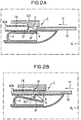
- FIG. 2A shows an example of the arrangement of the arrangement shown in FIG Holding device V shown in a housing of a data carrier evaluation device KL, for example a chip or Magnetic card reader - hereinafter referred to as KL card reader -, shown.
- the card reader KL is for example Part of a public or private card phone - not shown.
- the card reader KL a contacting unit KON for reading out or processing of information stored on a chip or magnetic card CK on, the contacting unit KON being more integral Part of a guide channel arranged in the card reader KL FK for inserting chip or magnetic cards.
- the device V shown in FIG arranged in the housing of the card reader KL or there locked that the spring-loaded locking device SUT together with the two ramp-shaped opening elements R in protrude the guide channel FK, or are arranged there.
- the locking device SUT with the two opening elements R through the Bending element B which is locked on the housing of the card reader KL Holding device V by a arranged in the guide channel FK and correspondingly designed opening OF in the Guide channel FK pressed so that this through the locking device SUT is closed.
- the one at the end of the bent part B arranged stop surface AF is against the outer wall W of the guide channel FK pressed.
- 2A is an example one arranged at an input E of the guide channel FK Chip or magnetic card CK shortly before insertion in the sliding direction sr in the card reader KL or in its Guide channel FK shown.
- the locking device SUT In the closed state of the locking device SUT two wedge-shaped opening elements R each in the edge area of the guide channel FK arranged, the slopes of the opening elements R one from the guide channel direction or from the direction of insertion sr of the chip or magnetic card Have direction.
- the two wedge-shaped opening elements R By inserting a chip or Magnetic card CK in the guide channel FK of the card reader KL, the two wedge-shaped opening elements R through the pushing forces acting on the slopes of the ramps R. down and thus the locking device SUT off the guide channel FK pressed - by a dashed Arrow indicated in FIG 2B.
- the chip or magnetic card CK is so far in the guide channel FK of the card reader KL can be inserted until the contact unit KON of the card reader KL with one or more corresponding Counter-contacting units - not shown - the inserted card CK for bidirectional data exchange connected is.
- the inserted chip card CK can at any time again from the guide channel FK of the card reader KL can be removed or pulled out, with the resilient designed bending part B when pulling out the card CK SUT locking device together with the two opening elements R are pressed back into the guide channel FK and thus the guide channel FK is closed again - cf.
- FIG 2A The chip or magnetic card CK is so far in the guide channel FK of the card reader KL can be inserted until the contact unit KON of the card reader KL with one or more corresponding Counter-contacting units - not shown - the inserted card CK for bidirectional data exchange connected is.
- the inserted chip card CK can at any time again from the guide channel FK of the card reader KL can be
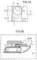
- FIG. 3A shows a top view
- FIG. 3B shows a side view the closed arrangement of the locking device SUT with one inserted into the entrance area E of the guide channel FK, coin-shaped object GM, KM.
- an insertion for example, one with a large diameter Coin GM in the entrance area E of the guide channel 3A with closed locking device SUT the arranged on the side edges of the guide channel FK, wedge-shaped opening elements R - or their slopes - not reached due to the large rounding of the GM coin, whereby the locking device SUT according to the invention not down and therefore not pressed out of the guide channel FK can be.
- the locking device can be advantageous SUT slightly inclined against the insertion direction sr of the guide channel FK, or the CP card be inclined - cf. 3B -, What the locking effect of the locking device SUT further is improved because the inclined locking device SUT by trying to insert or push in one Coin GM, KM in the guide channel FK through on the inclined Locking device SUT rather acting pushing forces pressed more strongly into the guide channel FK, i.e. in the blocking direction becomes.
- FIG. 3A is a cover in the entrance area E of the guide channel FK AB arranged through which the insertion of one small diameter coins KM in the guide channel FK prevents and thus the insertion of smaller ones Coins KM possibly in the area of the slopes of the wedge-shaped Opening elements R and a possible opening or pushing the shooting device SUT away from the guide channel FK is prevented.
Landscapes
- Physics & Mathematics (AREA)
- General Physics & Mathematics (AREA)
- Engineering & Computer Science (AREA)
- Theoretical Computer Science (AREA)
- Control Of Vending Devices And Auxiliary Devices For Vending Devices (AREA)
- Conveying Record Carriers (AREA)
- Testing Of Coins (AREA)
Applications Claiming Priority (2)
| Application Number | Priority Date | Filing Date | Title |
|---|---|---|---|
| DE19824815 | 1998-06-03 | ||
| DE1998124815 DE19824815A1 (de) | 1998-06-03 | 1998-06-03 | Datenträger-Auswertevorrichtung mit einem Führungskanal für tragbare, kartenförmige Datenträger |
Publications (2)
| Publication Number | Publication Date |
|---|---|
| EP0962879A2 true EP0962879A2 (fr) | 1999-12-08 |
| EP0962879A3 EP0962879A3 (fr) | 2002-01-16 |
Family
ID=7869789
Family Applications (1)
| Application Number | Title | Priority Date | Filing Date |
|---|---|---|---|
| EP99110574A Withdrawn EP0962879A3 (fr) | 1998-06-03 | 1999-06-01 | Dispositif pour l'évaluation de porteurs de données portables en forme de carte avec un canal de guidage |
Country Status (2)
| Country | Link |
|---|---|
| EP (1) | EP0962879A3 (fr) |
| DE (1) | DE19824815A1 (fr) |
Cited By (2)
| Publication number | Priority date | Publication date | Assignee | Title |
|---|---|---|---|---|
| FR2837958A1 (fr) * | 2002-03-27 | 2003-10-03 | Amphenol Tuchel Elect | Connecteur pour carte a memoire comportant un volet de protection contre la salete |
| EP1975853A1 (fr) | 2007-03-30 | 2008-10-01 | AMPHENOL-TUCHEL ELECTRONICS GmbH | Unité de lecture et/ou d'écriture |
Family Cites Families (3)
| Publication number | Priority date | Publication date | Assignee | Title |
|---|---|---|---|---|
| DE4139482A1 (de) * | 1991-11-29 | 1993-06-03 | Man Technologie Gmbh | Schutzeinrichtung fuer eletronische kartenlesegeraete |
| DE9213283U1 (de) * | 1992-10-02 | 1992-11-26 | Siemens AG, 8000 München | Kartenleser |
| DE19547060C2 (de) * | 1995-12-18 | 1998-05-14 | Bernhard Vogler | Einrichtung zum Verschließen und/oder Sperren des Karteneinführungsschlitzes an Codekartenlesern |
-
1998
- 1998-06-03 DE DE1998124815 patent/DE19824815A1/de not_active Withdrawn
-
1999
- 1999-06-01 EP EP99110574A patent/EP0962879A3/fr not_active Withdrawn
Cited By (2)
| Publication number | Priority date | Publication date | Assignee | Title |
|---|---|---|---|---|
| FR2837958A1 (fr) * | 2002-03-27 | 2003-10-03 | Amphenol Tuchel Elect | Connecteur pour carte a memoire comportant un volet de protection contre la salete |
| EP1975853A1 (fr) | 2007-03-30 | 2008-10-01 | AMPHENOL-TUCHEL ELECTRONICS GmbH | Unité de lecture et/ou d'écriture |
Also Published As
| Publication number | Publication date |
|---|---|
| EP0962879A3 (fr) | 2002-01-16 |
| DE19824815A1 (de) | 1999-12-09 |
Similar Documents
| Publication | Publication Date | Title |
|---|---|---|
| DE10021396B4 (de) | Kontaktiereinrichtung für eine Chipkarte, insbesondere eine SIM-Karte | |
| DE19521721B4 (de) | Geschirmte Kontaktiereinrichtung | |
| DE69418810T2 (de) | Tragbare Mehrzweckkarte für Personalrechner | |
| DE19806844C2 (de) | Tragbares Telefongerät | |
| EP0775964B1 (fr) | Unité de contact pour supports de composants électroniques en forme de carte | |
| DE60220480T2 (de) | Kartenverbinderseinrichtung für verschiede Kartentypen | |
| DE69834302T2 (de) | Chipkarten-Verbinder | |
| DE60025936T2 (de) | Umschalteinrichtung für kartenverbinder | |
| DE69420442T2 (de) | Tragbarer, mit einer Karte kombinierter Fernsprechapparat | |
| DE10038287A1 (de) | Steckkarte für elektronische Geräte | |
| DE3343727A1 (de) | Kartenleser fuer kassiervorrichtungen | |
| DE69625407T2 (de) | SIM-Kartenverbinder | |
| DE602004013036T2 (de) | Speicherkartenverbinder mit kartenauswurfmechanismus | |
| DE10245483A1 (de) | Steckkarten-Adapter | |
| EP1008280A1 (fr) | Unite de mise en contact pour un element de support en forme de carte de modules electroniques, en particulier correspondant a la norme pcmcia | |
| DE60126201T2 (de) | Elektrischer Kartenverbinder | |
| DE9012889U1 (de) | Kartenlesegerät für die elektrische Nachrichtentechnik | |
| EP0894310B1 (fr) | Dispositif de lecture de cartes | |
| EP0731415B1 (fr) | Boítier pour carte à puce | |
| EP0924867A2 (fr) | Lecteur de carte pour émetteur-récepteurs mobiles | |
| DE3020728A1 (de) | Wertkartenfernsprecher | |
| EP0962879A2 (fr) | Dispositif pour l'évaluation de porteurs de données portables en forme de carte avec un canal de guidage | |
| DE69602731T2 (de) | Kartensteckverbinderanordnung | |
| DE60319356T2 (de) | Speicherkartenverbinder mit sicherung gegen fehlerhafte karteneinführung | |
| DE69803549T2 (de) | Kartenleseverbindung |
Legal Events
| Date | Code | Title | Description |
|---|---|---|---|
| PUAI | Public reference made under article 153(3) epc to a published international application that has entered the european phase |
Free format text: ORIGINAL CODE: 0009012 |
|
| AK | Designated contracting states |
Kind code of ref document: A2 Designated state(s): AT BE CH CY DE DK ES FI FR GB GR IE IT LI LU MC NL PT SE |
|
| AX | Request for extension of the european patent |
Free format text: AL;LT;LV;MK;RO;SI |
|
| PUAL | Search report despatched |
Free format text: ORIGINAL CODE: 0009013 |
|
| AK | Designated contracting states |
Kind code of ref document: A3 Designated state(s): AT BE CH CY DE DK ES FI FR GB GR IE IT LI LU MC NL PT SE |
|
| AX | Request for extension of the european patent |
Free format text: AL;LT;LV;MK;RO;SI |
|
| RIC1 | Information provided on ipc code assigned before grant |
Free format text: 7G 06K 13/08 A, 7G 06K 7/00 B |
|
| AKX | Designation fees paid | ||
| REG | Reference to a national code |
Ref country code: DE Ref legal event code: 8566 |
|
| STAA | Information on the status of an ep patent application or granted ep patent |
Free format text: STATUS: THE APPLICATION IS DEEMED TO BE WITHDRAWN |
|
| 18D | Application deemed to be withdrawn |
Effective date: 20020717 |