EP0962881B1 - Crayon d'entrée de coordonées - Google Patents
Crayon d'entrée de coordonées Download PDFInfo
- Publication number
- EP0962881B1 EP0962881B1 EP99108693A EP99108693A EP0962881B1 EP 0962881 B1 EP0962881 B1 EP 0962881B1 EP 99108693 A EP99108693 A EP 99108693A EP 99108693 A EP99108693 A EP 99108693A EP 0962881 B1 EP0962881 B1 EP 0962881B1
- Authority
- EP
- European Patent Office
- Prior art keywords
- wheel
- stylus
- teeth
- finger
- finger wheel
- Prior art date
- Legal status (The legal status is an assumption and is not a legal conclusion. Google has not performed a legal analysis and makes no representation as to the accuracy of the status listed.)
- Expired - Lifetime
Links
Images


Classifications
-
- G—PHYSICS
- G08—SIGNALLING
- G08C—TRANSMISSION SYSTEMS FOR MEASURED VALUES, CONTROL OR SIMILAR SIGNALS
- G08C21/00—Systems for transmitting the position of an object with respect to a predetermined reference system, e.g. tele-autographic system
-
- G—PHYSICS
- G06—COMPUTING OR CALCULATING; COUNTING
- G06F—ELECTRIC DIGITAL DATA PROCESSING
- G06F3/00—Input arrangements for transferring data to be processed into a form capable of being handled by the computer; Output arrangements for transferring data from processing unit to output unit, e.g. interface arrangements
- G06F3/01—Input arrangements or combined input and output arrangements for interaction between user and computer
- G06F3/03—Arrangements for converting the position or the displacement of a member into a coded form
- G06F3/033—Pointing devices displaced or positioned by the user, e.g. mice, trackballs, pens or joysticks; Accessories therefor
- G06F3/0354—Pointing devices displaced or positioned by the user, e.g. mice, trackballs, pens or joysticks; Accessories therefor with detection of two-dimensional [2D] relative movements between the device, or an operating part thereof, and a plane or surface, e.g. 2D mice, trackballs, pens or pucks
- G06F3/03545—Pens or stylus
Definitions
- This invention relates to a stylus device for use with a digitizer or other coordinate input system according to the preamble of claim 1. More particularly, this invention relates to a pointing stylus including a rotatable side wheel, wherein manipulation and rotation of the side wheel enables the user to vary a graphical or control parameter (e.g. line thickness, color, pen-stroke, shading, line texture, etc.) of an image being drawn via the coordinate input system.
- a graphical or control parameter e.g. line thickness, color, pen-stroke, shading, line texture, etc.
- Other possible uses include scrolling in text documents with the finger wheel, navigation in a third dimension of a 3D space, zooming in and out of a document or graphical representation, and the like.
- a touchpad may replace the finger wheel on the side of the stylus.
- Pointers for use in conjunction with coordinate input systems are known in the art. For example, see U.S. Patent Nos. 5,731,807; 5,028,745; 5,061,828; 5,109,141; 5,055,831; and 5,004,871. These pointers may be used in conjunction with coordinate input systems, such as digitizer systems.
- U.S. Patent No. 5,731,807 discloses a mouse for inputting coordinate data into a coordinate input system. Unfortunately, some users of graphics tablets dislike mouse devices and prefer stylus-like devices for drawing because of their aesthetic feel.
- U.S. Patent No. 5,004,871 discloses stylus having a pressure sensitive side switch which protrudes outwardly from a housing at an angle which is transverse to the housing.
- the magnitude of force (i.e. pressure) applied to the switch determines the signal which is output by the stylus.
- the transverse alignment of the switch relative to the housing in the '871 patent, and the switch's transverse movement relative to the housing's axis are undesirable.
- the transverse extension or protrusion of the switch renders it susceptible to damage, and furthermore it is difficult for some users to accurately adjust transverse finger pressure while writing (e.g. drawing) with the stylus.
- the requirement for accurate and adjustable transverse finger pressure during drawing strokes is undesirable and difficult to achieve, as is the requirement for transverse protrusion of a stylus side switch. It would be desirable if these characteristics could be eliminated.
- U.S. Patent No. 5,109,141 discloses a digitizer stylus including a switch moveable along the side of the housing, and wherein the switch retains the position it is moved to after it is released by the user.
- the switch in the '141 patent is movable along the housing side parallel to a longitudinal axis of the housing.
- Patent abstract of Japan, Vol. 1998, No. 10, 31. August 1998 discloses a stylus device according to the preamble of claim 1, which has a rotatable dial instead of a switch as an finger input device, which can be easily used during drawing strokes and does not require a sliding movement.
- Figure 1 is a side partial cross sectional view of an airbrush-simulating stylus including a finger wheel according to an embodiment of this invention.
- Figure 2 is a side plan view of the airbrush-simulating stylus of Figure 1.
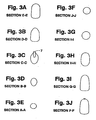
- Figures 3(a) through 3(j) are front cross sectional views of the Fig. 1 stylus taken along the corresponding sectional lines shown in Figure 2.
- Figure 4 is a top plan view of a stylus including a finger wheel according to another embodiment of this invention, this embodiment being elongated in design.
- Figure 5 is a side plan view of the stylus of the Figure 4 embodiment.
- Figure 6 is a front view of the Figure 4 stylus, showing the finger wheel sticking up slightly relative to the stylus' housing.
- Figure 7 is a rear view of the Figure 4 stylus, showing a conventional on/off switch sticking up slightly relative to the stylus' housing.
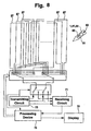
- Figure 8 is a schematic diagram illustrating a digitizer tablet system, the styli of all embodiments herein being useable in conjunction with the digitizer tablet coordinate input system of Figure 8.
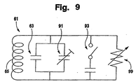
- Figure 9 is a circuit diagram illustrating circuitry, including a tuning circuit and a potentiometer in a stylus according to any embodiment of this invention.
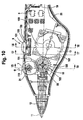
- Figure 10 is a side partial cross sectional view of an airbrush simulating stylus including a finger wheel according to the Figure 1 embodiment of this invention, showing the interior of the stylus in more detail than in Figure 1.
- Figure 11 is a front cross sectional view of the Figure 14 stylus taken along sectional line 15-15 shown in Figure 10.
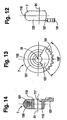
- Figure 12 is a front cross sectional view of the Figure 14 stylus taken along sectional line 16-16 shown in Figure 10.
- Figure 13 is a front cross sectional view of the Figure 14 stylus taken along the sectional line 17-17 shown in Figure 10.
- Figure 14 is a rear plan view of the finger wheel of the Figure 10-13 embodiment of this invention.
- Figure 15 is a side elevational view of the finger wheel of Figure 14.
- Figure 16 is a front cross sectional view of the finger wheel of Figures 10-15.
- FIGS 1-3 show stylus 1 which simulates an airbrush according to an embodiment of this invention.
- Stylus 1 is not perfectly elongated in shape, but instead includes protruding grip area 3 which enables the stylus to simulate the shape of an airbrush.
- Stylus 1 includes hollow housing 5, rotatable finger wheel or dial 7 for inputting variable data depending upon the amount or degree to which the wheel is adjusted, on/off data input switch 9, pressure sensitive stylus tip 11 for contacting the tablet, longitudinal stylus axis 12, pressure sensing device 13 for sensing the amount of pressure the user applies to the stylus against the tablet via tip 11, intermediate gear wheel 15, rotary potentiometer 17 for sensing the angular degree to which finger wheel 7 is adjusted or rotated, main processing chip 19, printed circuit board 21 including at least one flat surface that defines a plane, trimmers 23, eraser assembly 25, eraser tip 27, and eraser pressure sensor 29.
- housing 5 includes an aperture or slit defined therein for allowing an upper portion of wheel 7 to protrude outwardly from the interior of housing 5 through the aperture or slit thereby causing the protruding portion of the wheel 7 to be exposed so that the user can touch it to cause wheel 7 to rotate about fixed wheel axis 31.
- wheel 7 is only permitted to rotate in one direction about axis 31 from its original neutral position (i.e. from a predetermined position) and then back to its neutral position, although bi-directional rotation relative to a predetermined position is possible in alternative embodiments.
- Finger wheel 7 is mounted within housing 5 so as to be rotatable about fixed axis 31.
- a user of stylus 1 may use his/her finger (e.g. index finger) to manipulate wheel 7 so as to rotate it about axis 31 while drawing/writing.
- the periphery of wheel 7 is also in operative communication (e.g. contacting) with rotatable gear wheel 15.
- Gear wheel 15 is mounted within housing 5 so as to be rotatable about stationary axis 33.
- Gear wheel 15 is in operative communication (e.g. contacting) with both finger wheel 7 and potentiometer 17.
- Rotary potentiometer 17 determines how far (i.e. to what degree) gear wheel 15 rotates and thus to what degree the user has manipulated or rotated wheel 7.
- Potentiometer 17 detects the degree of rotation of wheel 15 and thus can determine the degree or amount of rotation of finger wheel 7 caused by the user. Potentiometer 17, in combination with other circuitry in the stylus, then causes the stylus to output an electromagnetic wave signal to the tablet (or computer) indicating how far wheel 7 was detected to have been rotated. The amount or degree of rotation determines how much a chosen graphical parameter is varied.
- the user can rotate finger wheel 7 so as to continually adjust graphics or control parameter data such as, for example, the thickness of the line/stroke being drawn, the shading of the line/stroke being drawn, the color of the line/stroke being drawn, the texture of the line/stroke being drawn, the density of the line/stroke being drawn, and/or the type of brush or stylus being simulated in the drawing of the line/stroke being drawn.
- wheel 7 is not an on/off switch, but is a variably rotatable wheel which can cause the stylus to output a plurality of different signals or levels dependent upon the direction and/or angular degree to which wheel 7 is rotated about axis 31. These different signals may be used to continually vary or adjust any of a plurality of parameters by different amounts while writing/drawing, including those listed above.
- a line of a first thickness may be drawn via the tablet on a display by the stylus in a coordinate input system if wheel 7 is rotated ten degrees clockwise about axis 31 from a predetermined initial position, a line of a second thickness drawn if wheel 7 is rotated by twelve degrees clockwise about axis 31, a line of a third thickness drawn if wheel 7 is rotated by fourteen degrees clockwise about axis 31, and so on.
- a line of varying thickness may be drawn if the user rotates wheel 7 while drawing the line.
- the image parameter (e.g. line width, gray scale, color, etc.) to be altered or adjusted by finger wheel 7 is varied in a manner/amount as a linear function of the degree of rotation of wheel 7.
- the width of the line being drawn by stylus 1 may increase a given amount (e.g. 0.1 mm) on a corresponding LCD display screen for every angular degree of rotation that wheel 7 is rotated from its origin about axis 31.
- the parameter to be adjusted by wheel 7 may be varied in a non-linear manner with respect to the degree of wheel 7 rotation.
- the amount of increase for line thickness may be a first amount (e.g.
- a second greater amount e.g. 0.125 mm for a total increase of 0.225 mm
- a third amount e.g. 0.150 mm for a total thickness increase of 0.375 mm
- wheel/dial 7 is not biased in any direction by any type of spring or the like, and requires user manipulation to rotate the wheel to and from all rotational positions.
- finger wheel 7 may be biased toward a neutral or zero degree position (i.e. predetermined position). It may be biased to this position by a biasing spring, or any other type of basing device.
- a biasing spring or any other type of basing device.
- the stylus when line width is the parameter to be varied by wheel 7, the stylus will output a signal indicating a given line width to be drawn when wheel 7 is in the neutral position.
- the line width When wheel 7 is rotated about axis 31 in one direction the line width will get progressively smaller depending upon the degree of rotation so that the user can continuously vary the line width by varying the rotational position of wheel 7.
- the potentiometer When the user releases wheel 7, it will rotate back to the neutral position and the line width will go back to the given line width.
- the potentiometer will cause the stylus to output a signal instructing the system that the line width is to increase, and the line width of the image being drawn will progressively increase depending upon the degree of rotation.
- the finger wheel is not spring loaded or biased in any manner.
- the finger wheel when rotated so that the protruding surface of the wheel is rotated all the way to its furthest position in one direction (e.g. all the way counterclockwise in Figure 1), it will report a signal indicative of zero levels when at this predetermined position, and when the wheel is rotated all the way in the opposite direction, it will report a full number of levels.
- the number of levels reported to the digitizer system by the stylus is a function of the rotational or radial angular position of the finger wheel relative to its zero-level predetermined position.
- finger wheel 7 has a circular periphery which extends 360 degrees about axis 31 so as to form substantially a complete circle thereabout.
- the upper section of the wheel for contact with finger(s) of the user may be rubber-coated 123 (see Fig. 20) for improved control by finger(s), while the lower portion (from about 120-130 angular degrees about axis 31) has gear teeth 101 for interacting with the gearwheel and is thus not rubber-coated.
- Wheel 7 in certain embodiments may have only a partially circular periphery that extends less than 360 degrees about axis 31.
- wheel 7 may take the shape of a half-pie (i.e. half-circle) or three quarters (i.e. 270 ) of a pie in certain embodiments while still being referred to as a "wheel" 7. Also, the periphery of wheel 7 need not be continuous about axis 31.
- wheel/dial 7 is circular, although that it may take the form of other shapes such as oval, triangular, etc. Additionally, as shown in Figs. 18-20, wheel/dial 7 need simply be rotatable about a central axis 31, and need not be perfectly circular or have equal thicknesses throughout to be a "wheel” or dial” in accordance with this invention. The requirements for "wheel” or “dial” 7 is that it be rotatable in some manner about an axis (e.g. 31) in order to input variable data so as to adjust a parameter of an image being drawn by the stylus.
- an axis e.g. 31
- stylus 1 may include circuit board 21 positioned within housing 5 for the purpose of supporting numerous electronic chips (e.g. 19) and other circuitry utilized by the stylus.
- the stylus may include a tuning circuit mounted therein, including a coil and capacitor (see Figure 13), so that the stylus does not require batteries and does not require a cord to connect the stylus to the tablet.
- stylus 1 in certain embodiments includes a tuning circuit and is not connected to the corresponding tablet in any way. Eraser system 25 may also be provided in optional embodiments.
- conventional on/off switch 9 may also be provided so as to simulate mouse "clicks" or other functionality in certain embodiments.
- switch 9 has only two states in certain embodiments, (i.e. on and off)
- finger wheel 7 has a plurality of potential states equal to the number of potential angular positions that wheel 7 may be manipulated to.
- Wheel 7 is also positioned in certain embodiments, as illustrated in Figs. 1-3, so that rotational axis 31 is substantially perpendicular to the elongated axis 12 of the stylus and also to the axis of eraser tip 27.
- axis 31 may be moved ninety degrees from its illustrated position so that it would be substantially parallel to the axis 12 of the stylus and to the axis of eraser tip 27, and thus wheel 7 would be rotated by a finger of the user moving back and forth across the housing.
- FIGs 4-7 illustrate another embodiment of this invention including elongated stylus 41 which has finger wheel.
- Stylus 41 includes an elongated housing 43 which houses the elements discussed and illustrated above with regard to the Fig. 1-3 embodiment of this invention, which operate in the same manner described and shown above.
- Housing 41 does not include an airbrush simulating grip portion 3.
- This embodiment also does not include a gearwheel due to the size of the housing.
- Finger wheel 7 is directly mounted on the rotary axis of the rotary potentiometer 17. Mechanically, there is reduced play between gears, and the design allows components to fit in the housing.
- Figure 8 illustrates a digitizer tablet system which any stylus of any embodiment of this invention may be used in conjunction with, although the styli of this invention may also be used in conjunction with any other conventional digitizer or other coordinate input systems.
- the stylus would include a tuning circuit 61 therein having, for example, a capacitor 63 operatively associated with an inductive coil 65.
- the stylus' tuning circuit 61 communicates with the tablet's overlapping conductive loop coils 67 as, for example, described in U.S. Patent No. 5,028,745, in order to enable the loop coils of the tablet to detect the presence and location of the stylus.
- Loop coils of the tablet generate electromagnetic waves which are received by the stylus' tuning circuit 61 which then transmits another electromagnetic wave back to the tablet which is detected by loop coils of the tablet.
- the electromagnetic wave which is transmitted from the tuning circuit to loop coils of the tablet includes information therein which indicates the status or degree of rotation of wheel 7 (or area 51) as detected by potentiometer 17. This allows the stylus to indicate to the tablet the status of wheel 7 which in turn is used to vary the graphical parameter to be varied.
- the tuning circuit in the stylus receives waves from one set of loop coils in the tablet and sends waves back to the same set of loop coils so that the same tablet coils both transmit and detect waves.
- the tuning circuit may send back waves to a different set of loop coils in the tablet than the coil(s) which sent energizing waves to the tuning circuit.
- the tablet system may include receiving circuit 71, transmitting circuit 73, and processing device 75. Loop coils 67 of the tablet detect the waves sent from the stylus and detect the position of the stylus, with this information then being forwarded to processing device 75 which instructs the corresponding display system 74 as to the position of the stylus.
- FIG. 9 illustrates a circuit which may be utilized within any of the styli of the aforesaid embodiments of this invention.
- the stylus circuitry includes tuning circuit 61 including inductive coil 65 and capacitor 63.
- Variable capacitor 91 represents tip pressure sensitive switch 13 in that the capacitance will vary as a function of the pressure which is applied to the tablet surface by the stylus via tip 11.
- the tuning circuit has a resonant frequency capable of approximate tuning with the frequency generated from the loop coils of the tablet when electric power is applied to the sensing coils.
- switch 93 representative of on/off side switch 9.
- the tuning circuit may emit frequency A when switch 93 is open and different frequency B when switch 93 is closed, or the phase of the signal output by the tuning circuit may change as a function of whether switch 93 is open or closed.
- Potentiometer 17 includes a variable resistance 99 in certain embodiments which varies as a function of the rotational position of finger wheel 7.
- resistance 99 will have a first value when wheel 7 is in its neutral predetermined position, a second and different resistance when wheel 7 is rotated to a given point in the clockwise direction, and so on.
- each potential position of wheel 7 will dictate a given value of resistance 99 of the potentiometer.
- a variable capacitance or a variable inductance could be used instead of variable resistance 99 for the potentiometer in certain alternative embodiments of this invention.
- Figure 10 is a partial enlarged view of the Figure 1 stylus, showing in more detail finger wheel 7, gear wheel 15, and potentiometer 17.
- Figures 11-13 are front cross sectional views of the Fig. 10 stylus taken along the illustrated sectional lines. Additionally, Figures 14-16 show finger wheel 7 of the embodiment of Figure 10.
- finger wheel or dial 7 defines a peripheral surface which is at least partially toothed 101.
- a peripheral surface which is at least partially toothed 101.
- more than half of the outer diametric periphery of wheel 7 is approximately smooth and does not have teeth defined therein.
- a plurality of teeth 101 e.g. seven
- Potentiometer wheel 16 is driven by gear wheel 15.
- the outer peripheral portion of the wheel 7 including teeth 101 defined therein represents an arc of from about 80-140 degrees about axis 31, more preferably from about 90-130 degrees, and most preferably about 108 degrees, where the center of wheel also defines the center of the arc.
- the remainder of the outer periphery of wheel 7 is substantially free of teeth.
- the toothless portion of the outer periphery of wheel 7 is for the user to contact with his/her finger(s) in order to rotate the wheel/dial 7 in order to alter a parameter of the image being drawn/written with the stylus, and the toothed portion of wheel 7 is typically not exposed for user manipulation and is for interacting with corresponding teeth 103 defined in a peripheral portion of intermediate gear wheel 15 (or gears of a potentiometer), as shown in Figures 10 and 11.
- Teeth 103 of gear wheel 15 mesh with and interact with teeth 101 of finger wheel 7, while teeth 105 of gear wheel 15 mesh with and interact with teeth 107 of potentiometer dial portion 17.
- Teeth 103 of gear wheel 15 mesh with and interact with teeth 101 of finger wheel 7, while teeth 105 of gear wheel 15 mesh with and interact with teeth 107 of potentiometer dial portion 17.
- Arcuately relative to the center thereof, from about 40-180 degrees of the periphery of a rotatable wheel or disc of potentiometer 17 includes teeth 107 in certain embodiments.
- Intermediate gear wheel 15 includes a diametric peripheral first portion which includes teeth 103 and a diametric peripheral second portion which includes teeth 105 defined therein.
- the peripheries of these first and second coaxial portions are substantially annular in shape about axis 33, and are preferably covered by teeth 103 and 105, respectively, around all 360 degrees thereof. Alternatively, portions of these peripheries of gear wheel 15 need not be covered by teeth.
- the outer or larger peripheral toothed portion which includes teeth 105 has a substantially larger diameter than the inner or smaller peripheral portion which includes teeth 103, so that the rotatable wheel or toothed portion of the potentiometer (which is caused to rotate by teeth 105) is rotated at a different speed than wheel 7.
- Teeth 101 of finger wheel 7 mesh with teeth 103 of gear wheel 15 thereby causing the gear wheel to rotate along with the finger wheel.
- gear wheel 15 When gear wheel 15 is caused to rotate in such a manner, this causes its outer periphery including teeth 105 to also rotate.
- Teeth 105 mesh with teeth 107 of the potentiometer wheel or dial and cause it to rotate about its center axis.
- the degree to which the potentiometer dial or wheel 109 rotates about its axis determines the output of the potentiometer and is a function of the degree of rotation of finger wheel 7.
- gear wheel 15 may be formed of a single integrally formed piece of plastic or metal, with teeth 103 and 105 defined in the two coaxial, yet offset, peripheral portions thereof.
- outer peripheral teeth 105 and inner peripheral teeth 103 each form a substantial circle about the same axis 111.
- teeth 103 are laterally offset slightly from teeth 105 so that the teeth 101 of wheel 7 can contact teeth 103 without meshing or contacting teeth 105, while teeth 105 are simultaneously meshing with and causing gear teeth 107 of the potentiometer to rotate thereby enabling the potentiometer to detect the degree to which wheel or dial 7 has been rotated from a predetermined position.
- pulleys, cable, belts, or any other linkage could be used instead of the intermediate gear wheel to transfer rotary movement from the finger to a detecting device such as a potentiometer.
- finger wheel 7 is rotatable about axis 31.
- notch 113 may be defined in the outer periphery of the wheel to enable a user to feel where a given portion of the wheel is positioned radially relative to the stylus housing.
- notch 113 may be located in the middle of the slit in the housing of the stylus, and directly above axis 31 as shown in Figs. 11 and 15.
- the user may rotate the wheel about axis 31 in a rotational direction away from the predetermined position to, for example, the position illustrated in Fig.
- notch 113 has been rotated degrees counterclockwise to a new position.
- the degree of angular rotation which wheel/dial 7 is rotated from its predetermined position dictates the amount which the parameter is altered.
- the angular degree of rotation is detected by potentiometer 17 as discussed above.
- dial/wheel 7 may, in certain embodiments, include an integrally formed portion 115 of molded plastic or metal. Integral portion 115 defines central cavity 117 encompassing axis 31 which enables wheel 7 to fit over tube 119 as shown in Fig. 11 (i.e. tube 119 or any other elongated member fits into annular or otherwise shaped cavity 117 so that the wheel can rotate relative thereto about axis 31, as the tube and wheel are substantially coaxial). Integral portion 115 further includes substantially T-shaped annular projection 121 in certain embodiments for allowing rubber or elastomer peripheral grip material 123 to be attached to an outer portion of wheel 7.
- elastomeric gripping material 123 is attached to wheel 7 at peripheral portions thereof which do not include teeth 101 (e.g. T-shaped connection member 121 need not be located in toothed areas of the wheel).
- Portion 121 and elastomeric material portion 123 are each at least partially annular in shape about axis 31, in that each at least partially arcs about central wheel axis 31 to some angular degree.
- Integral portion 115 of wheel 7 further includes tooth base portion 127 in which teeth 101 are defined. Tooth base 127 is at least partially annular in shape about axis 31 as shown in Fig. 15, and in certain embodiments, may extend outwardly from a central area of portion 115, and include teeth 101 defined in an outer peripheral portion thereof as shown in Figs.
- Tooth base portion 127 defines an annular arc about axis 31 to the same degree as do teeth 101, or a slightly larger arc in certain embodiments (e.g. from about 80-140 degrees, more preferably from about 90-130 degrees about axis 31). Additionally, although annular T-shaped member 121 (and grip portion 123) and tooth base portion 127 may co-occupy arcuate space about axis 31 in certain embodiments, this is not the case in the embodiment illustrated in Figs. 14-16, where T-shaped portion 121 occupies a given portion of the 360 degree arc about axis 31 and portion 127 occupies substantially the rest of the arc about axis 31 where T-shaped portion 121 is not positioned.
- tooth support portion 127 of wheel/dial 7 has a first axial thickness relative to axis 31, while the central portion 115 of wheel/dial 7 has a second greater axial thickness relative to axis 31, with the greater axial thickness of portion 115 enabling the grip member 123 to be more adequately attached to the dial, and the thinner nature of portion 127 and thus teeth 101 defined therein enabling teeth 101 and portion 127 to fit into teeth 103 of gear wheel without interfering with teeth 105.
- substantially flat circuit board 21 defines a plane the top of which is viewed in Fig. 10. This plane of board 21 extends downward in Fig. 14 from the top of the stylus toward its bottom, and has chip 19 mounted thereon.
- Switch 9 includes finger button 131 and pressure sensitive switching detection mechanism 133.
- Detection mechanism 133 is mounted upon approximately flat platform or surface 135.
- Platform 135 may be part of switch 9 (switch 9 may be an on/off switch, or any other type of pressure sensitive device capable of outputting multiple signals based upon the amount of pressure received), or alternatively may be a support surface for supporting device(s) which are part of the switch. In either case, stationary platform 135 is operatively associated with switch 9 and button 131, and is located below button 131 along button axis 134. As shown best in Fig.
- surface 135 is mounted between a first support structure extending from one side of the housing interior including parallel support extensions 137 and 139, and a second support structure extending from the other or opposite side of the housing interior including parallel support extensions 141 and 143.
- Support extensions 137, 139, 141, and 143 each define a plane substantially perpendicular to that of circuit board 21.
- Supports 137, 139, 141, and 143 may be of plastic and integrally formed with hollow stylus housing 5, although they alternatively may be of metal, or also may not be integrally formed with the housing and may be simply attached to the interior thereof.
- the plane of circuit board 21 is substantially parallel (i.e. parallel plus of minus about ten degrees) to the illustrated housing side-wall portions 136 in Figs. 11-13, and also substantially perpendicular to the plane of platform 135.
- axis 134 along which button 131 is pressed (and released) during switch operation is substantially parallel to (i.e. parallel plus or minus about ten degrees), or even co-planar with in certain embodiments, the plane of circuit board 21.
- Button movement axis 134 (see Fig. 12) is also substantially perpendicular to the planes defined by supports 137, 139, 141, and 143, as well as to surface 135.
- circuit board 21 This unique positioning of circuit board 21 relative to the switching mechanism and switch support structures enables the finger wheel structures to be fit into a smaller housing. While in the illustrated embodiments of this invention, button 131 is part of an on/off switch 9, this need not be the case in all embodiments as it is recognized that switch 9 may instead be a variable pressure sensitive switch can detect a plurality (e.g. five, ten, a hundred, or even a thousand) different pressure levels applied to the button by the user.
- a plurality e.g. five, ten, a hundred, or even a thousand
Landscapes
- Engineering & Computer Science (AREA)
- General Engineering & Computer Science (AREA)
- Theoretical Computer Science (AREA)
- Physics & Mathematics (AREA)
- General Physics & Mathematics (AREA)
- Human Computer Interaction (AREA)
- Position Input By Displaying (AREA)
Claims (10)
- Crayon pour être utilisé dans un système numérique d'entrée de coordonnées, comprenant :caractérisé en ce que la roue tactile (7) comprend une multitude de dents (101) définies dans une partie périphérique de la roue ; etun boítier (5, 41, 45) ;un circuit électronique (21) disposé dans ledit boítier ;une roue tactile (7) ou un cadran de réglage qui peut être tourné autour d'un axe central (31) par un utilisateur ; le degré selon lequel la roue tactile (7) est tournée déterminant le degré par lequel un paramètre de contrôle ou graphique utilisé par le système d'entrée de données est varié ;
une roue dentée (15) est fournie qui comprend un premier jeu de dents (103) pour engrener lesdites dents (101) de ladite roue tactile (7) et un deuxième jeu de dents (105) pour s'engrener avec les dents correspondantes (107) sur un potentiomètre (17) de sorte que le potentiomètre (17) détecte ledit degré auquel la roue tactile (7) se met à tourner et provoque une variation dudit paramètre en fonction de la rotation ;
où ledit premier jeu de dents (103) ayant une roue d'engrenage (15) définit une partie périphérique ayant un diamètre différent de la partie périphérique dudit deuxième jeu de dents (105) sur ladite roue dentée (15). - Le stylo de la revendication 1, dans lequel ladite roue tactile (7) comprend une partie (115) formée en une pièce incluant une partie (121) ayant au moins en partie une forme de T qui permet de monter une partie d'engrenage (123) sur ladite roue tactile (7).
- Le stylo selon la revendication 2, dans lequel ladite partie d'engrenage (123) comprend un matériau élastomère fixé sur moins de la moitié de la périphérie entière de ladite roue tactile (7) et dans lequel ladite partie (121) en forme de T s'étend sur la moitié des 360 degrés autour dudit axe central de ladite roue (7) et ladite partie (121) en forme de T s'étendant de façon annulaire autour d'au moins 180 degrés autour dudit axe central (31).
- Le stylo selon l'une des revendications précédentes, dans lequel ledit axe de roue (31) est orienté de manière essentiellement parallèle à un axe longitudinal dudit stylo et dans lequel lesdites dents (101) de ladite roue tactile (7) s'étendent au dessus d'un arc atteignant environ 80-140 degrés autour dudit axe central (31) de ladite roue tactile (7).
- Le stylo selon l'une quelconque des revendications précédentes, comprenant en outre un circuit (61) de contrôle pour recevoir des ondes électromagnétiques à partir de bobines (67) en boucle d'une tablette et pour transmettre des ondes électromagnétiques à des bobines (67) en boucle de la tablette .
- Le stylo selon l'une quelconque des revendications précédentes , dans lequel les bobines en boucle à partir desquelles les ondes sont reçues, sont différentes des bobines (67) en boucle auxquelles les ondes provenant du circuit (61) d'adaptation sont transmises.
- Le stylo selon n'importe laquelle des revendications précédentes, dans lequel la roue tactile n'est pas précontrainte par ressort dans n'importe qu'elle position et le stylo émet un signal à un système de tablette correspondant qui indique la position de rotation de la roue tactile (7) par rapport à une position de rotation prédéterminée.
- Le stylo selon n'importe laquelle des revendications précédentes, dans lequel le boítier (5, 41, 45) comprend une ouverture définie dans le boítier pour permettre à ladite roue tactile (7) de faire saillie vers l'extérieur par ladite ouverture.
- Le stylo selon n'importe laquelle des revendications précédentes, dans lequel le paramètre comprend : l'épaisseur de ligne , le scrolling , la navigation la couleur, l'ombrage , l'échelle des gris et la texture.
- Un système d'entrée de données graphique comprenant une tablette de numérisation et le stylo selon une quelconque des revendications précédentes.
Applications Claiming Priority (2)
| Application Number | Priority Date | Filing Date | Title |
|---|---|---|---|
| US09/090,307 US6259438B1 (en) | 1998-06-04 | 1998-06-04 | Coordinate input stylus |
| US90307 | 1998-06-04 |
Publications (3)
| Publication Number | Publication Date |
|---|---|
| EP0962881A2 EP0962881A2 (fr) | 1999-12-08 |
| EP0962881A3 EP0962881A3 (fr) | 2002-07-17 |
| EP0962881B1 true EP0962881B1 (fr) | 2003-10-15 |
Family
ID=22222218
Family Applications (1)
| Application Number | Title | Priority Date | Filing Date |
|---|---|---|---|
| EP99108693A Expired - Lifetime EP0962881B1 (fr) | 1998-06-04 | 1999-05-18 | Crayon d'entrée de coordonées |
Country Status (6)
| Country | Link |
|---|---|
| US (2) | US6259438B1 (fr) |
| EP (1) | EP0962881B1 (fr) |
| JP (1) | JP4267758B2 (fr) |
| KR (1) | KR100511830B1 (fr) |
| DE (1) | DE69912022T2 (fr) |
| TW (1) | TW434514B (fr) |
Families Citing this family (135)
| Publication number | Priority date | Publication date | Assignee | Title |
|---|---|---|---|---|
| US6512513B2 (en) * | 1919-04-01 | 2003-01-28 | Wacom Co., Ltd. | Pointer for use in digitizer systems |
| JP2004501464A (ja) * | 2000-06-22 | 2004-01-15 | コーニンクレッカ フィリップス エレクトロニクス エヌ ヴィ | パラメータ制御システム |
| US7102628B2 (en) * | 2000-10-06 | 2006-09-05 | International Business Machines Corporation | Data steering flip pen system |
| US6879930B2 (en) * | 2001-03-30 | 2005-04-12 | Microsoft Corporation | Capacitance touch slider |
| US7279646B2 (en) * | 2001-05-25 | 2007-10-09 | Intel Corporation | Digital signature collection and authentication |
| US7126590B2 (en) * | 2001-10-04 | 2006-10-24 | Intel Corporation | Using RF identification tags in writing instruments as a means for line style differentiation |
| US6882340B2 (en) * | 2001-10-19 | 2005-04-19 | Wacom Co., Ltd. | Electronic pen |
| US7394346B2 (en) * | 2002-01-15 | 2008-07-01 | International Business Machines Corporation | Free-space gesture recognition for transaction security and command processing |
| US6727439B2 (en) * | 2002-01-28 | 2004-04-27 | Aiptek International Inc. | Pressure sensitive pen |
| US7392396B2 (en) * | 2002-03-07 | 2008-06-24 | Symbol Technologies, Inc. | Transaction device with noise signal encryption |
| FR2838065B1 (fr) * | 2002-04-09 | 2005-11-18 | Bertrand Marsac | Souris d'ordinateur pour jeu video |
| TW544974B (en) * | 2002-07-25 | 2003-08-01 | Aiptek Int Inc | An electromagnetic inductive system with multi-antenna loop layout and battery less pointer device and its method for locating the coordinate |
| WO2004023382A1 (fr) * | 2002-09-04 | 2004-03-18 | Fachhochschule Regensburg | Systeme d'ecriture acoustique biometrique et procede d'identification de personnes et reconnaissance de l'ecriture a l'aide de donnees biometriques |
| US20040155862A1 (en) * | 2002-12-10 | 2004-08-12 | Higginson Timothy B. | Universal detachable cursor control member for an electronic component |
| US7203384B2 (en) * | 2003-02-24 | 2007-04-10 | Electronic Scripting Products, Inc. | Implement for optically inferring information from a planar jotting surface |
| US6985138B2 (en) | 2003-08-29 | 2006-01-10 | Motorola, Inc. | Input writing device |
| US7110100B2 (en) * | 2003-11-04 | 2006-09-19 | Electronic Scripting Products, Inc. | Apparatus and method for determining an inclination of an elongate object contacting a plane surface |
| US20050104871A1 (en) * | 2003-11-15 | 2005-05-19 | Qing Liu | Computer input device |
| US7961909B2 (en) | 2006-03-08 | 2011-06-14 | Electronic Scripting Products, Inc. | Computer interface employing a manipulated object with absolute pose detection component and a display |
| US7826641B2 (en) * | 2004-01-30 | 2010-11-02 | Electronic Scripting Products, Inc. | Apparatus and method for determining an absolute pose of a manipulated object in a real three-dimensional environment with invariant features |
| US9229540B2 (en) | 2004-01-30 | 2016-01-05 | Electronic Scripting Products, Inc. | Deriving input from six degrees of freedom interfaces |
| US8542219B2 (en) * | 2004-01-30 | 2013-09-24 | Electronic Scripting Products, Inc. | Processing pose data derived from the pose of an elongate object |
| US7023536B2 (en) * | 2004-03-08 | 2006-04-04 | Electronic Scripting Products, Inc. | Apparatus and method for determining orientation parameters of an elongate object |
| WO2005096772A2 (fr) | 2004-04-01 | 2005-10-20 | Finepoint Innovations, Inc. | Systeme transducteur de surface sans fil |
| JP4405335B2 (ja) * | 2004-07-27 | 2010-01-27 | 株式会社ワコム | 位置検出装置、及び、入力システム |
| US7696987B2 (en) * | 2005-03-04 | 2010-04-13 | Smart Technologies Ulc | Touch panel and method of manufacturing the same |
| US7886941B2 (en) | 2005-04-25 | 2011-02-15 | Meadwestvaco Calmar Inc. | Dispenser having air tight spout |
| JP2007072555A (ja) * | 2005-09-05 | 2007-03-22 | Sony Corp | 入力ペン |
| WO2007115428A1 (fr) * | 2006-03-31 | 2007-10-18 | Intel Corporation | Système ultrasonique multimode |
| US10168801B2 (en) * | 2006-08-31 | 2019-01-01 | Semiconductor Energy Laboratory Co., Ltd. | Electronic pen and electronic pen system |
| TW200839576A (en) * | 2007-03-16 | 2008-10-01 | Behavior Tech Computer Corp | Computer cursor control method and apparatus thereof |
| US8243028B2 (en) * | 2008-06-13 | 2012-08-14 | Polyvision Corporation | Eraser assemblies and methods of manufacturing same |
| TWI385594B (zh) * | 2008-09-23 | 2013-02-11 | Univ Nat Taiwan Science Tech | 繪圖之輸入裝置 |
| KR20100063969A (ko) * | 2008-12-04 | 2010-06-14 | 삼성전자주식회사 | 터치 입력 장치를 이용한 정보 입력 방법 및 시스템 |
| TWD133907S1 (zh) * | 2008-12-26 | 2010-03-21 | 和冠股份有限公司 | 電子筆 |
| TWD133724S (zh) * | 2008-12-26 | 2010-03-11 | 和冠股份有限公司 | 電子筆 |
| CN101539815A (zh) * | 2009-02-25 | 2009-09-23 | 韩鼎楠 | 多点触摸屏操作工具 |
| US8514187B2 (en) * | 2009-09-30 | 2013-08-20 | Motorola Mobility Llc | Methods and apparatus for distinguishing between touch system manipulators |
| JP5430339B2 (ja) * | 2009-10-19 | 2014-02-26 | 株式会社ワコム | 位置検出装置及び位置指示器 |
| US9110534B2 (en) * | 2010-05-04 | 2015-08-18 | Google Technology Holdings LLC | Stylus devices having variable electrical characteristics for capacitive touchscreens |
| US9310923B2 (en) | 2010-12-03 | 2016-04-12 | Apple Inc. | Input device for touch sensitive devices |
| US8928635B2 (en) | 2011-06-22 | 2015-01-06 | Apple Inc. | Active stylus |
| US9329703B2 (en) * | 2011-06-22 | 2016-05-03 | Apple Inc. | Intelligent stylus |
| US8638320B2 (en) | 2011-06-22 | 2014-01-28 | Apple Inc. | Stylus orientation detection |
| US9268416B2 (en) | 2011-08-05 | 2016-02-23 | Htc Corporation | Touch control pen, touching control apparatus and touching detection method with image delete function thereof |
| US9164598B2 (en) | 2011-10-28 | 2015-10-20 | Atmel Corporation | Active stylus with surface-modification materials |
| US8963885B2 (en) | 2011-11-30 | 2015-02-24 | Google Technology Holdings LLC | Mobile device for interacting with an active stylus |
| US9063591B2 (en) | 2011-11-30 | 2015-06-23 | Google Technology Holdings LLC | Active styluses for interacting with a mobile device |
| KR20130104649A (ko) * | 2012-03-14 | 2013-09-25 | 이명우 | 터치스크린 입력용 도전성 펜 |
| KR101282430B1 (ko) * | 2012-03-26 | 2013-07-04 | 삼성디스플레이 주식회사 | 스타일러스, 압력 검출 시스템 및 그의 구동방법 |
| WO2013153551A1 (fr) * | 2012-04-08 | 2013-10-17 | N-Trig Ltd. | Stylet et numériseur pour manipulation 3d d'objets virtuels |
| US9261961B2 (en) | 2012-06-07 | 2016-02-16 | Nook Digital, Llc | Accessibility aids for users of electronic devices |
| US8803850B2 (en) * | 2012-06-15 | 2014-08-12 | Blackberry Limited | Stylus with control ring user interface |
| US9658746B2 (en) | 2012-07-20 | 2017-05-23 | Nook Digital, Llc | Accessible reading mode techniques for electronic devices |
| US9557845B2 (en) | 2012-07-27 | 2017-01-31 | Apple Inc. | Input device for and method of communication with capacitive devices through frequency variation |
| US9652090B2 (en) | 2012-07-27 | 2017-05-16 | Apple Inc. | Device for digital communication through capacitive coupling |
| US9176604B2 (en) | 2012-07-27 | 2015-11-03 | Apple Inc. | Stylus device |
| US9001064B2 (en) | 2012-12-14 | 2015-04-07 | Barnesandnoble.Com Llc | Touch sensitive device with pinch-based archive and restore functionality |
| US9030430B2 (en) | 2012-12-14 | 2015-05-12 | Barnesandnoble.Com Llc | Multi-touch navigation mode |
| US9134893B2 (en) | 2012-12-14 | 2015-09-15 | Barnes & Noble College Booksellers, Llc | Block-based content selecting technique for touch screen UI |
| US8963865B2 (en) | 2012-12-14 | 2015-02-24 | Barnesandnoble.Com Llc | Touch sensitive device with concentration mode |
| US9134903B2 (en) | 2012-12-14 | 2015-09-15 | Barnes & Noble College Booksellers, Llc | Content selecting technique for touch screen UI |
| US9477382B2 (en) | 2012-12-14 | 2016-10-25 | Barnes & Noble College Booksellers, Inc. | Multi-page content selection technique |
| US9448719B2 (en) | 2012-12-14 | 2016-09-20 | Barnes & Noble College Booksellers, Llc | Touch sensitive device with pinch-based expand/collapse function |
| US9134892B2 (en) | 2012-12-14 | 2015-09-15 | Barnes & Noble College Booksellers, Llc | Drag-based content selection technique for touch screen UI |
| US9367185B2 (en) | 2012-12-18 | 2016-06-14 | Logitech Europe S.A. | Method and system for discriminating stylus and touch interactions |
| US9158393B2 (en) | 2012-12-18 | 2015-10-13 | Logitech Europe S.A. | Active stylus for touch sensing applications |
| US9836154B2 (en) | 2013-01-24 | 2017-12-05 | Nook Digital, Llc | Selective touch scan area and reporting techniques |
| US9971495B2 (en) | 2013-01-28 | 2018-05-15 | Nook Digital, Llc | Context based gesture delineation for user interaction in eyes-free mode |
| KR102065703B1 (ko) * | 2013-02-07 | 2020-02-11 | 삼성전자주식회사 | 터치 펜, 터치 펜 인식을 위한 전자 장치 및 그 운용 방법 |
| US9367161B2 (en) | 2013-03-11 | 2016-06-14 | Barnes & Noble College Booksellers, Llc | Touch sensitive device with stylus-based grab and paste functionality |
| US9946365B2 (en) | 2013-03-11 | 2018-04-17 | Barnes & Noble College Booksellers, Llc | Stylus-based pressure-sensitive area for UI control of computing device |
| US9626008B2 (en) | 2013-03-11 | 2017-04-18 | Barnes & Noble College Booksellers, Llc | Stylus-based remote wipe of lost device |
| US9189084B2 (en) | 2013-03-11 | 2015-11-17 | Barnes & Noble College Booksellers, Llc | Stylus-based user data storage and access |
| US9600053B2 (en) | 2013-03-11 | 2017-03-21 | Barnes & Noble College Booksellers, Llc | Stylus control feature for locking/unlocking touch sensitive devices |
| US9766723B2 (en) | 2013-03-11 | 2017-09-19 | Barnes & Noble College Booksellers, Llc | Stylus sensitive device with hover over stylus control functionality |
| US9261985B2 (en) | 2013-03-11 | 2016-02-16 | Barnes & Noble College Booksellers, Llc | Stylus-based touch-sensitive area for UI control of computing device |
| US9785259B2 (en) | 2013-03-11 | 2017-10-10 | Barnes & Noble College Booksellers, Llc | Stylus-based slider functionality for UI control of computing device |
| US9448643B2 (en) | 2013-03-11 | 2016-09-20 | Barnes & Noble College Booksellers, Llc | Stylus sensitive device with stylus angle detection functionality |
| US9760187B2 (en) | 2013-03-11 | 2017-09-12 | Barnes & Noble College Booksellers, Llc | Stylus with active color display/select for touch sensitive devices |
| US9891722B2 (en) | 2013-03-11 | 2018-02-13 | Barnes & Noble College Booksellers, Llc | Stylus-based notification system |
| US9632594B2 (en) | 2013-03-11 | 2017-04-25 | Barnes & Noble College Booksellers, Llc | Stylus sensitive device with stylus idle functionality |
| US10048775B2 (en) | 2013-03-14 | 2018-08-14 | Apple Inc. | Stylus detection and demodulation |
| US9146672B2 (en) | 2013-04-10 | 2015-09-29 | Barnes & Noble College Booksellers, Llc | Multidirectional swipe key for virtual keyboard |
| US8966617B2 (en) | 2013-04-23 | 2015-02-24 | Barnesandnoble.Com Llc | Image pattern unlocking techniques for touch sensitive devices |
| US8963869B2 (en) | 2013-04-23 | 2015-02-24 | Barnesandnoble.Com Llc | Color pattern unlocking techniques for touch sensitive devices |
| WO2014174771A1 (fr) * | 2013-04-25 | 2014-10-30 | シャープ株式会社 | Système d'écran tactile et dispositif électronique |
| US9152321B2 (en) | 2013-05-03 | 2015-10-06 | Barnes & Noble College Booksellers, Llc | Touch sensitive UI technique for duplicating content |
| US9612740B2 (en) | 2013-05-06 | 2017-04-04 | Barnes & Noble College Booksellers, Inc. | Swipe-based delete confirmation for touch sensitive devices |
| KR102087392B1 (ko) * | 2013-05-13 | 2020-04-14 | 삼성전자주식회사 | 동작 방법 및 그 전자 장치 |
| US10019153B2 (en) | 2013-06-07 | 2018-07-10 | Nook Digital, Llc | Scrapbooking digital content in computing devices using a swiping gesture |
| US9244603B2 (en) | 2013-06-21 | 2016-01-26 | Nook Digital, Llc | Drag and drop techniques for discovering related content |
| US9423932B2 (en) | 2013-06-21 | 2016-08-23 | Nook Digital, Llc | Zoom view mode for digital content including multiple regions of interest |
| US9400601B2 (en) | 2013-06-21 | 2016-07-26 | Nook Digital, Llc | Techniques for paging through digital content on touch screen devices |
| US9696819B2 (en) | 2013-06-28 | 2017-07-04 | Blackberry Limited | Method and apparatus pertaining to a stylus having a multi-level force-sensitive user interface |
| EP2818980B1 (fr) * | 2013-06-28 | 2022-12-21 | BlackBerry Limited | Procédé et appareil se rapportant à un stylet possédant une interface utilisateur avec une sensibilité multiniveaux à la force |
| TW201502877A (zh) * | 2013-07-09 | 2015-01-16 | Raydium Semiconductor Corp | 觸控筆及其操作方法 |
| US10845901B2 (en) | 2013-07-31 | 2020-11-24 | Apple Inc. | Touch controller architecture |
| US9552049B1 (en) * | 2013-09-25 | 2017-01-24 | Amazon Technologies, Inc. | Activating and using device with a grip switch |
| US9575948B2 (en) | 2013-10-04 | 2017-02-21 | Nook Digital, Llc | Annotation of digital content via selective fixed formatting |
| US20150116290A1 (en) * | 2013-10-25 | 2015-04-30 | Livescribe Inc. | Combined activation mechanism of retractable marker and power status for an electronic pen |
| AU2014363901A1 (en) * | 2013-12-10 | 2016-07-07 | De Lage Landen Financial Services | Method and system for negotiating, generating, documenting, and fulfilling vendor financing opportunities |
| CN103645814A (zh) * | 2013-12-18 | 2014-03-19 | 刘保伸 | 多功能数位触控器结构 |
| US10620796B2 (en) | 2013-12-19 | 2020-04-14 | Barnes & Noble College Booksellers, Llc | Visual thumbnail scrubber for digital content |
| US9588979B2 (en) | 2013-12-31 | 2017-03-07 | Barnes & Noble College Booksellers, Llc | UI techniques for navigating a file manager of an electronic computing device |
| US10915698B2 (en) | 2013-12-31 | 2021-02-09 | Barnes & Noble College Booksellers, Llc | Multi-purpose tool for interacting with paginated digital content |
| US9367208B2 (en) | 2013-12-31 | 2016-06-14 | Barnes & Noble College Booksellers, Llc | Move icon to reveal textual information |
| US9424241B2 (en) | 2013-12-31 | 2016-08-23 | Barnes & Noble College Booksellers, Llc | Annotation mode including multiple note types for paginated digital content |
| US9792272B2 (en) | 2013-12-31 | 2017-10-17 | Barnes & Noble College Booksellers, Llc | Deleting annotations of paginated digital content |
| US9367212B2 (en) | 2013-12-31 | 2016-06-14 | Barnes & Noble College Booksellers, Llc | User interface for navigating paginated digital content |
| US10534528B2 (en) | 2013-12-31 | 2020-01-14 | Barnes & Noble College Booksellers, Llc | Digital flash card techniques |
| US10331777B2 (en) | 2013-12-31 | 2019-06-25 | Barnes & Noble College Booksellers, Llc | Merging annotations of paginated digital content |
| US9817489B2 (en) | 2014-01-27 | 2017-11-14 | Apple Inc. | Texture capture stylus and method |
| WO2015116074A1 (fr) * | 2014-01-30 | 2015-08-06 | Hewlett-Packard Development Company, L.P. | Crayon à stylet réglable |
| CN103885615B (zh) * | 2014-03-18 | 2016-08-24 | 东南大学 | 一种用于移动终端交互的便携式力触觉反馈电容笔 |
| US9400570B2 (en) | 2014-11-14 | 2016-07-26 | Apple Inc. | Stylus with inertial sensor |
| KR102307692B1 (ko) * | 2014-11-28 | 2021-10-05 | 삼성전자 주식회사 | 펜 입력장치, 그 입력 좌표 보정방법 및 이를 제공하는 전자장치 |
| US10061449B2 (en) | 2014-12-04 | 2018-08-28 | Apple Inc. | Coarse scan and targeted active mode scan for touch and stylus |
| US9575573B2 (en) * | 2014-12-18 | 2017-02-21 | Apple Inc. | Stylus with touch sensor |
| WO2016186191A1 (fr) | 2015-05-21 | 2016-11-24 | 株式会社ワコム | Stylet actif |
| CN107810467B (zh) * | 2015-06-26 | 2021-03-02 | 三星电子株式会社 | 输入装置、用于从输入装置接收信号的电子设备及其控制方法 |
| KR102344356B1 (ko) | 2015-06-26 | 2021-12-29 | 삼성전자주식회사 | 입력 장치, 그 입력 장치로부터 신호를 입력받는 전자기기 및 그 제어방법 |
| KR102354327B1 (ko) | 2015-08-10 | 2022-01-21 | 삼성전자주식회사 | 데이터 입력 시스템 및 그 동작 방법 |
| US10168804B2 (en) | 2015-09-08 | 2019-01-01 | Apple Inc. | Stylus for electronic devices |
| US11577159B2 (en) | 2016-05-26 | 2023-02-14 | Electronic Scripting Products Inc. | Realistic virtual/augmented/mixed reality viewing and interactions |
| US10474277B2 (en) | 2016-05-31 | 2019-11-12 | Apple Inc. | Position-based stylus communication |
| US10532449B2 (en) * | 2017-07-26 | 2020-01-14 | Carolyn Hieronymus | Orthotic removal tool |
| US11526217B2 (en) | 2017-10-30 | 2022-12-13 | Hewlett-Packard Development Company, L.P. | Stylus |
| US11188144B2 (en) | 2018-01-05 | 2021-11-30 | Samsung Electronics Co., Ltd. | Method and apparatus to navigate a virtual content displayed by a virtual reality (VR) device |
| CN112930515B (zh) * | 2018-11-09 | 2024-06-04 | 株式会社和冠 | 电子擦除工具及书写信息处理系统 |
| KR20200115889A (ko) * | 2019-03-28 | 2020-10-08 | 삼성전자주식회사 | 전자 펜을 통한 사용자 입력에 기초하여 동작을 실행하는 전자 디바이스 및 그 동작 방법 |
| JP7482706B2 (ja) | 2020-07-08 | 2024-05-14 | 株式会社ワコム | スタイラス及びセンサコントローラによって実行される方法、スタイラス、及びセンサコントローラ |
| US12153764B1 (en) | 2020-09-25 | 2024-11-26 | Apple Inc. | Stylus with receive architecture for position determination |
| CN116324685A (zh) * | 2020-11-27 | 2023-06-23 | 株式会社和冠 | 电子笔 |
| WO2022224578A1 (fr) * | 2021-04-23 | 2022-10-27 | 株式会社ワコム | Dispositif de commande et ordinateur |
Family Cites Families (31)
| Publication number | Priority date | Publication date | Assignee | Title |
|---|---|---|---|---|
| JPS6370326A (ja) | 1986-09-12 | 1988-03-30 | Wacom Co Ltd | 位置検出装置 |
| JPS63286924A (ja) * | 1987-05-20 | 1988-11-24 | Amada Metrecs Co Ltd | 電子式製図装置の入力ペン |
| US5014044A (en) | 1988-05-27 | 1991-05-07 | Summagraphics Corporation | Magnification assembly for digitizer cursor |
| US5109141A (en) | 1989-11-13 | 1992-04-28 | Summagraphics Corporation | Digitizer stylus with z-axis side control |
| US5327161A (en) | 1989-08-09 | 1994-07-05 | Microtouch Systems, Inc. | System and method for emulating a mouse input device with a touchpad input device |
| US5231380A (en) | 1989-08-09 | 1993-07-27 | Microtouch Systems, Inc. | Input keyboard touch-sensitive adjunct |
| US5055831A (en) | 1989-10-06 | 1991-10-08 | Summagraphics Corporation | Cursor for digitizer tablet |
| US5004871A (en) | 1989-11-13 | 1991-04-02 | Summagraphics Corporation | Digitizer stylus having side switch |
| US5061828A (en) | 1989-11-13 | 1991-10-29 | Summagraphics Corporation | Digitizer stylus with Z-axis side pressure control |
| US5111005A (en) | 1990-10-04 | 1992-05-05 | Summagraphics Corporation | Graphics tablet with n-dimensional capability |
| US5666113A (en) | 1991-07-31 | 1997-09-09 | Microtouch Systems, Inc. | System for using a touchpad input device for cursor control and keyboard emulation |
| US5565658A (en) * | 1992-07-13 | 1996-10-15 | Cirque Corporation | Capacitance-based proximity with interference rejection apparatus and methods |
| US5296871A (en) | 1992-07-27 | 1994-03-22 | Paley W Bradford | Three-dimensional mouse with tactile feedback |
| US5384688A (en) * | 1993-03-08 | 1995-01-24 | Calcomp Inc. | Three-dimensional circuits for digitizer and pen-based computer system pen cursors |
| JP3378337B2 (ja) | 1994-02-24 | 2003-02-17 | 株式会社ワコム | 位置検出装置及びその位置指示器 |
| JPH07248870A (ja) | 1994-03-11 | 1995-09-26 | Wacom Co Ltd | データ整合方法、座標入力方法及び座標入力システム |
| US5613137A (en) | 1994-03-18 | 1997-03-18 | International Business Machines Corporation | Computer system with touchpad support in operating system |
| US5681220A (en) | 1994-03-18 | 1997-10-28 | International Business Machines Corporation | Keyboard touchpad combination in a bivalve enclosure |
| JPH07271501A (ja) | 1994-03-31 | 1995-10-20 | Wacom Co Ltd | 表示画面における表示物の表示方法 |
| US5469194A (en) | 1994-05-13 | 1995-11-21 | Apple Computer, Inc. | Apparatus and method for providing different input device orientations of a computer system |
| JP3502664B2 (ja) | 1994-06-20 | 2004-03-02 | 株式会社ワコム | 位置検出装置 |
| JPH08137602A (ja) * | 1994-11-09 | 1996-05-31 | Alps Electric Co Ltd | スタイラスペン |
| US5805144A (en) * | 1994-12-14 | 1998-09-08 | Dell Usa, L.P. | Mouse pointing device having integrated touchpad |
| JPH096518A (ja) | 1995-06-16 | 1997-01-10 | Wacom Co Ltd | サイドスイッチ機構及びスタイラスペン |
| JPH09258881A (ja) * | 1996-03-26 | 1997-10-03 | Smk Corp | 感圧式3次元タブレットと感圧式3次元タブレットの操作データ検出方法 |
| US5731807A (en) | 1996-04-23 | 1998-03-24 | Sun Microsystems, Inc. | Apparatus and method for customizing the shape of a computer mouse to an individual's hand |
| DE19623468A1 (de) * | 1996-06-12 | 1997-12-18 | Wacom Co Ltd | Positionserfassungseinrichtung und Positionszeigeeinrichtung |
| US6130666A (en) * | 1996-10-07 | 2000-10-10 | Persidsky; Andre | Self-contained pen computer with built-in display |
| JPH10133805A (ja) * | 1996-10-31 | 1998-05-22 | Wacom Co Ltd | 位置指示器 |
| JPH10171583A (ja) * | 1996-12-05 | 1998-06-26 | Wacom Co Ltd | 位置検出装置およびその位置指示器 |
| US5959616A (en) * | 1997-12-23 | 1999-09-28 | International Business Machines Corporation | Computer input stylus and color control system |
-
1998
- 1998-06-04 US US09/090,307 patent/US6259438B1/en not_active Expired - Lifetime
-
1999
- 1999-05-18 DE DE69912022T patent/DE69912022T2/de not_active Expired - Lifetime
- 1999-05-18 EP EP99108693A patent/EP0962881B1/fr not_active Expired - Lifetime
- 1999-06-01 KR KR10-1999-0019977A patent/KR100511830B1/ko not_active Expired - Fee Related
- 1999-06-03 TW TW088109189A patent/TW434514B/zh not_active IP Right Cessation
- 1999-06-04 JP JP15793099A patent/JP4267758B2/ja not_active Expired - Fee Related
-
2001
- 2001-01-30 US US09/771,682 patent/US6556190B2/en not_active Expired - Fee Related
Also Published As
| Publication number | Publication date |
|---|---|
| US20010006383A1 (en) | 2001-07-05 |
| US6259438B1 (en) | 2001-07-10 |
| EP0962881A3 (fr) | 2002-07-17 |
| US6556190B2 (en) | 2003-04-29 |
| KR20000005797A (ko) | 2000-01-25 |
| KR100511830B1 (ko) | 2005-09-02 |
| DE69912022T2 (de) | 2004-08-12 |
| JP2000047805A (ja) | 2000-02-18 |
| EP0962881A2 (fr) | 1999-12-08 |
| JP4267758B2 (ja) | 2009-05-27 |
| DE69912022D1 (de) | 2003-11-20 |
| TW434514B (en) | 2001-05-16 |
Similar Documents
| Publication | Publication Date | Title |
|---|---|---|
| EP0962881B1 (fr) | Crayon d'entrée de coordonées | |
| US7466307B2 (en) | Closed-loop sensor on a solid-state object position detector | |
| US5963197A (en) | 3-D cursor positioning device | |
| US5175534A (en) | Computer input device using the movements of a user's fingers | |
| EP0964355B1 (fr) | Dispositif d'entrée de coordonnées pouvant être utilisé avec la main gauche ou la main droite | |
| US5936612A (en) | Computer input device and method for 3-D direct manipulation of graphic objects | |
| US7193612B2 (en) | Scrolling apparatus providing multi-directional movement of an image | |
| US7391410B2 (en) | Input device for touch screen | |
| US6075518A (en) | Rotational X-axis pointing device | |
| EP2613230A2 (fr) | Dispositif et procédé permettant de détecter un mouvement au moyen d'un capteur de proximité | |
| US20060001646A1 (en) | Finger worn and operated input device | |
| CN1232902C (zh) | 坐标输入记录笔及图形坐标输入系统 | |
| US5579032A (en) | Pointing device for a computer system | |
| CN112237736A (zh) | 使用触摸感应以使轨迹球表现得像操纵杆 | |
| RU2319998C2 (ru) | Устройство управления курсором | |
| US20040189606A1 (en) | Mouse having a massage feature | |
| JP2001134373A (ja) | 位置入力装置 | |
| EP1396813B1 (fr) | Entrées d'utilisateur sur un écran tactile | |
| KR20120070769A (ko) | 전자기기용 폴더형 휴대용 무선 입력 장치 | |
| JPH0540571A (ja) | 3次元位置入力方法および3次元位置入力装置 | |
| JP2005339109A (ja) | 情報入力装置 |
Legal Events
| Date | Code | Title | Description |
|---|---|---|---|
| PUAI | Public reference made under article 153(3) epc to a published international application that has entered the european phase |
Free format text: ORIGINAL CODE: 0009012 |
|
| AK | Designated contracting states |
Kind code of ref document: A2 Designated state(s): AT BE CH CY DE DK ES FI FR GB GR IE IT LI LU MC NL PT SE |
|
| AX | Request for extension of the european patent |
Free format text: AL;LT;LV;MK;RO;SI |
|
| PUAL | Search report despatched |
Free format text: ORIGINAL CODE: 0009013 |
|
| AK | Designated contracting states |
Kind code of ref document: A3 Designated state(s): AT BE CH CY DE DK ES FI FR GB GR IE IT LI LU MC NL PT SE |
|
| AX | Request for extension of the european patent |
Free format text: AL;LT;LV;MK;RO;SI |
|
| 17P | Request for examination filed |
Effective date: 20020704 |
|
| 17Q | First examination report despatched |
Effective date: 20021022 |
|
| GRAH | Despatch of communication of intention to grant a patent |
Free format text: ORIGINAL CODE: EPIDOS IGRA |
|
| AKX | Designation fees paid |
Designated state(s): DE GB |
|
| GRAH | Despatch of communication of intention to grant a patent |
Free format text: ORIGINAL CODE: EPIDOS IGRA |
|
| GRAA | (expected) grant |
Free format text: ORIGINAL CODE: 0009210 |
|
| AK | Designated contracting states |
Kind code of ref document: B1 Designated state(s): DE GB |
|
| REG | Reference to a national code |
Ref country code: GB Ref legal event code: FG4D |
|
| REG | Reference to a national code |
Ref country code: IE Ref legal event code: FG4D |
|
| REF | Corresponds to: |
Ref document number: 69912022 Country of ref document: DE Date of ref document: 20031120 Kind code of ref document: P |
|
| PLBE | No opposition filed within time limit |
Free format text: ORIGINAL CODE: 0009261 |
|
| STAA | Information on the status of an ep patent application or granted ep patent |
Free format text: STATUS: NO OPPOSITION FILED WITHIN TIME LIMIT |
|
| 26N | No opposition filed |
Effective date: 20040716 |
|
| REG | Reference to a national code |
Ref country code: IE Ref legal event code: MM4A |
|
| PGFP | Annual fee paid to national office [announced via postgrant information from national office to epo] |
Ref country code: DE Payment date: 20130522 Year of fee payment: 15 Ref country code: GB Payment date: 20130521 Year of fee payment: 15 |
|
| REG | Reference to a national code |
Ref country code: DE Ref legal event code: R119 Ref document number: 69912022 Country of ref document: DE |
|
| GBPC | Gb: european patent ceased through non-payment of renewal fee |
Effective date: 20140518 |
|
| REG | Reference to a national code |
Ref country code: DE Ref legal event code: R079 Ref document number: 69912022 Country of ref document: DE Free format text: PREVIOUS MAIN CLASS: G06K0011180000 Ipc: G06F0003033000 |
|
| REG | Reference to a national code |
Ref country code: DE Ref legal event code: R119 Ref document number: 69912022 Country of ref document: DE Effective date: 20141202 Ref country code: DE Ref legal event code: R079 Ref document number: 69912022 Country of ref document: DE Free format text: PREVIOUS MAIN CLASS: G06K0011180000 Ipc: G06F0003033000 Effective date: 20150206 |
|
| PG25 | Lapsed in a contracting state [announced via postgrant information from national office to epo] |
Ref country code: DE Free format text: LAPSE BECAUSE OF NON-PAYMENT OF DUE FEES Effective date: 20141202 |
|
| PG25 | Lapsed in a contracting state [announced via postgrant information from national office to epo] |
Ref country code: GB Free format text: LAPSE BECAUSE OF NON-PAYMENT OF DUE FEES Effective date: 20140518 |