EP0963063A2 - Système à laser pour la communication optique dans l'espace libre - Google Patents
Système à laser pour la communication optique dans l'espace libre Download PDFInfo
- Publication number
- EP0963063A2 EP0963063A2 EP99103122A EP99103122A EP0963063A2 EP 0963063 A2 EP0963063 A2 EP 0963063A2 EP 99103122 A EP99103122 A EP 99103122A EP 99103122 A EP99103122 A EP 99103122A EP 0963063 A2 EP0963063 A2 EP 0963063A2
- Authority
- EP
- European Patent Office
- Prior art keywords
- optical
- free
- signal
- lasercom
- space
- Prior art date
- Legal status (The legal status is an assumption and is not a legal conclusion. Google has not performed a legal analysis and makes no representation as to the accuracy of the status listed.)
- Withdrawn
Links
Images



Classifications
-
- H—ELECTRICITY
- H04—ELECTRIC COMMUNICATION TECHNIQUE
- H04B—TRANSMISSION
- H04B10/00—Transmission systems employing electromagnetic waves other than radio-waves, e.g. infrared, visible or ultraviolet light, or employing corpuscular radiation, e.g. quantum communication
- H04B10/11—Arrangements specific to free-space transmission, i.e. transmission through air or vacuum
- H04B10/118—Arrangements specific to free-space transmission, i.e. transmission through air or vacuum specially adapted for satellite communication
Definitions
- the present invention pertains to the field of free-space optical communication, particularly of the type used for two-way satellite communication, i.e. with an incoming Rx signal and an outgoing Tx signal.
- Effective communication between lasercom terminals requires precision pointing and tracking of the signal beams, and fine beam steering control is significant.
- rotating deflecting mirrors were the only reliable means of providing the required speed, range, accuracy and repeatability of beam steering.
- the optical subsystem for the previous lasercom terminal design requires a large number of optical surfaces.
- Each optical surface contributes deformation to the optical wavefront due to optical material imperfections, manufacturing errors, assembly and alignment errors and environmentally-introduced errors, such as temperature gradients and vibrations.
- satellite lasercom systems must propagate efficiently over thousands of kilometers, and must provide efficient coupling to the internal detector components.
- wavefront error must be minimized.
- a state-of-the-art optical terminal must be diffraction-limited with a very small wavefront deformation budget (i.e. total cumulative RMS error smaller than 0.07 of a wavelength of laser light). It is a technically challenging task to meet such a requirement in a system involving so many optical surfaces.
- each optical surface inherently scatters a portion of the beam, further reducing efficiency and elevating the stray light level. This can result in optical crosstalk between the transmission and receiving channels, in addition to other errors such as lower than expected BER, burst errors, and failure to acquire and track a signal in the presence of background radiation (such as from celestial sources, i.e. the Sun, Earth, Moon and planets, and also reflections and scatter from the satellite).
- background radiation such as from celestial sources, i.e. the Sun, Earth, Moon and planets, and also reflections and scatter from the satellite.
- Typical previous optical architectures require 50 optical surfaces or more, resulting in significant contributions to the above-noted problems.
- Fig. 1 shows a previous system that provides complete spatial separation of the Rx and Tx signals by using two telescopes 10, 12. While this design offers excellent control of stray light, it creates other problems such as significantly increasing mass, difficulty in alignment increased optomechanical complexity, and numerous optical surfaces in the subsystem.
- FIG. 2 Another approach is shown in Fig. 2, in which partial spatial separation is accomplished with a single telescope 20 and a shearing aperture 22, where Rx and Tx signals share the same optical path.
- the Tx source 24 is drawn off a separate optical path from the Rx detector 26 by e.g. a reflecting mirror 28.
- the shearing aperture approach While lighter in weight as less complex than the two-telescope design, the shearing aperture approach has poor stray light control since it is impossible to isolate the Tx beam from the Rx beam.
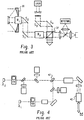
- Fig. 3 illustrates polarization isolation, in which a single telescope 30 is used, and the Rx and Tx signals are distinguished as perpendicular polarized beams separated by a polarizing diplexer 32, which sorts the Rx and Tx beams along separate optical paths.
- This method requires the highest quality polarization components and extremely tight control of the state of polarization as the Rx and Tx beams propagate through the subsystem.
- Fig. 4 illustrates dichroic isolation, in which a single telescope 40 is used, and different laser wavelengths are used for the Rx and Tx channels.
- the separate optical paths are defined by a dichroic beamsplitter 42. As a result, the two communicating terminals are precluded from operating at identical wavelengths.
- track detection is accomplished using a fast steering mirror (FSM) 50 which shifts in position to correct for mispoint in Rx channel beam.
- FSM fast steering mirror
- a beam splitter 52 directs the Rx signal to an Rx detector 54, and directs a portion of the Rx signal to a track detector 56. Since the Rx detector 54 and the track detector 56 are aligned, the FSM 50 cancels out mispoint on both simultaneously.
- the physical size of the track detector 56 limits the field of view of track detection. Thus, previous tracking systems are only sensitive to small angular mispoints, which makes signal acquisition and tracking more difficult.
- boresight alignment also poses a major technical challenge.
- the communication Rx and TX beams should be aligned within 1-3 microradians in free space.
- the corresponding misalignment requirement between channels may be even less than one microradian. While such boresight alignment is difficult to achieve during manufacture, it is even more difficult to maintain during launch deployment and on-orbit operation. Due to the long optics required for previous systems, the channel inputs must be separated by a great physical distance, which requires an extremely stable and expensive mechanical structure with tight controls over environmental variables.
- a free-space optical lasercom system including an optical subsystem for receiving an Rx signal and sending a Tx signal, wherein said optical subsystem establishes a focal plane.
- a first optical fiber is provided with an end coupled to the optical subsystem at a focal plane for directing the Rx signal to an Rx detector.
- a second optical fiber is provided with an end coupled to the optical subsystem at a focal plane for directing the Tx signal from a Tx laser source.
- a linear X-Y shifting means is disclosed for positioning the respective ends of the first and second optical fibers in the focal plane of the optical subsystem so as to maintain a desired coupling efficiency and also a required precision in pointing the Tx laser beam. Both fibers move in telecentric space so that a linear X-Y shift of the fiber is transformed into an angular shift of the beam in free space.
- Fig. 6 illustrates the optical structure of the lasercom terminal of a first embodiment of the present invention.
- An optical subsystem is used for receiving an Rx signal from a remote terminal, e.g. a satellite, and sending a Tx signal toward the same or a different remote terminal.
- the optical subsystem includes a dual telescope, i.e. an Rx telescope 100 and a Tx telescope 102, which form a respective pair of afocal reducers, and cooperate respectively with an Rx telecentric focusing lens 104 and a Tx telecentric focusing lens 106.
- the beams are collimated beams in the space between the telescopes 100, 102 and the focusing lenses 104, 106.
- the focusing lenses 104, 106 have a focal length effective to establish a focal plane for respective Rx optical fiber 110 and a Tx optical fiber 112.
- the present invention includes a precision X-Y linear shifter which is used to precisely position the optical fibers 110, 112 in the focal plane of the optical subsystem, so as to align the optical fibers with the respective beams.
- the Rx signal after entering the Rx optical fiber 110, passes through an Erbium Doped Fiber Amplifier (EDFA) 118 where it is detected by a lasercom detector 120, preferably a PIN diode, where it is transduced into an electrical signal which is processed by the terminal electronics.
- EDFA Erbium Doped Fiber Amplifier
- the Tx signal is generated by a laser diode 122, which in the illustrated embodiment is a 1552 nm infrared laser source.
- the Tx signal propagates through an EDFA 124 and outward through the optical system.
- An acquisition quadcell detector 108 is used with a beamsplitter and appropriate optics to provide proper signal acquisition for the terminal.
- the present invention uses a novel alignment system.
- the focusing lenses 104, 106 are telecentric, and thus have the property that the central ray of the optical beam passing through the lenses 104, 106 will be parallel to the optical axis of the lenses, regardless the angular orientation of the incident beam.
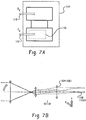
- the Rx telecentric lens 104 defines a flat focal plane for beams arriving from any angle of incidence. In this way, as shown in Fig. 7B, it is only necessary to linearly shift the Rx optical fiber 110 in an X-Y plane without rotation to align with the Rx signal beam, irrespective of the angle of incidence.
- a linear X-Y shift in the Tx fiber 112 results in an angular transformation of the propagating Tx beam through the Tx focusing lens 106.
- This linear-to-angular transformation is expressed as the "travel gain" G for effecting a fine alignment function of the system.
- the system can have a travel gain of about 1-6 microns of linear shift per microradian of angular displacement. (The fiber travel design parameters of a working embodiment is given below in Table I.)
- a travel stage i.e. an X-Y shifter 114 is used to linearly vary the position of both the Rx and Tx fibers 110, 112.
- a separate X-Y shifter 116 is added to the Tx stage to make minor adjustments to Tx fiber.
- this active alignment capability also permits active correction of boresight misalignment due to environmental changes, both long and short term, such as temperature changes, operation-induced deformations, and aging of the optomechanical structure.
- the channels can be located physically closer together reducing sensitivity to misalignment.
- the traveling fiber arrangement is significantly lightweight compared to the previous tracking mirror structures, resulting in considerable savings in payload delivery and reduced inertia during operation.
- the traveling stage 114 also carries a track detector 126, which moves together with the Rx fiber 110.
- the track detector 126 is preferably a multi-element detector, e.g. a single quadrant photodiode.
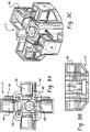
- the present X-Y shifter 114 can be realized by many different technologies, such as with piezoelectric, voice coil and electrostrictive actuators. An exemplary embodiment is shown in Figs. 9A, 9B, 9C and 9D, which is given for purposes of illustration alone, and is in no way intended to limit the scope of the invention.
- the travelling stage 114 includes a housing 180 which is held stationary against displacement.
- An X-motion fiber stage 182 is provided, and is displaced in an X-direction with a pair of X-motion actuators 184. The magnitude of displacement is measured with respective X-motion differential impedance transducers 186.
- a Y-motion fiber stage 188 is provided with respective Y-motion actuators 190 and transducers 192.
- a printed circuit assembly 194 is mounted on the Y-motion stage, which provides a mounting surface for the optical fiber tip 196, along with an electrical connection for the tracking detector 126.
- the track detector 126 and the Rx fiber tip are mounted on the same stage, with the Rx signal being divided by a beamsplitter. This results in the canceling out of mispoint in both elements simultaneously. Due to the telecentricity of the forward optics, angular mispoint of the incoming Rx signal is transformed into a linear shift that is compensated by the traveling stage 114, In this way, the field of view is not limited by the physical size of detector 126 itself, but only by the range of travel of the stage. In this way, the present invention is not limited as were previous systems, and a greater range of control is provided.
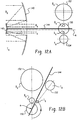
- the traveling stage 114 is used to effect fine positional adjustment of the fiber tips for pointing and tracking. As is shown in Figs. 10A and 10B, course adjustments in pointing and tracking capability are carried out in the present invention using a gimbaled mount for carrying the complete lasercom terminal 130.
- the gimbaled mount includes an azimuth actuator 132 and an elevation actuator 134 for pointing the laser com terminal 130 in a desired direction for communicating with a particular remote terminal.
- the actuators 132, 134 are sufficiently accurate so as to position the entire terminal in such a way as to align the traveling stage 114 with the remote terminal, in order to effect communication.
- the precision of the system must be greater than the total field of view of the track detector 126, so as to permit signal acquisition. The precision can vary with the requirements of the system, but for most configurations, an accuracy of within 10's of arcseconds is sufficient.
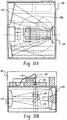
- FIG. 11A, 11B, 12A and 12B A first embodiment of the optical subsystem of the present invention is shown in Figs. 11A, 11B, 12A and 12B.
- the telescopes 100, 102 are in fact a single telescope system in which a common objective is used for both the Rx and Tx signal optical paths, to couple with the respective focusing lenses 104, 106.
- Mersenne telescope is preferably used, in which a pair of confocal parabolic mirrors 140, 142 are used to create an afocal telescope having a folded optical path, thereby reducing the size of the telescope.
- This system preferably provides an angular magnification of about 5x.
- a baffle 144 is preferably used to separate the optical paths, providing excellent control of stray light.
- Such a "two-in-one" telescope provides the benefits of the two-telescope approach while providing the reduced mass and optomechanical simplicity of previous single telescope designs.
- Figs. 11A and 11B illustrate the lasercom terminal 130 with the optical subsystem of the first embodiment.
- the telecentric focusing lenses 104, 106 include a positive lens group 146 and a negative lens group 148, properly configured in a telephoto arrangement to allow compact and efficient packaging of the various modules.
- the optical path can be folded by using a flat folding mirror 150 (as shown in Figs. 11A, 11B, 12A and 12B) to direct the light at a desired angle ⁇ , where ⁇ is preferably 90 degrees to the axis of rotation of the primary 140 and secondary 142.
- the physical size of the system is further reduced, resulting in considerable savings of mass and size, permitting the package to be gimbal mounted, eliminating the need for a complex coude mount as seen in previous systems.
- the invention is not limited to the above configuration, and many configurations may be contemplated without departing from the invention.
- the basic parameters of the optical subsystem are determined as follows:
- the entire afocal reducing system has a magnification M
- the focusing lenses 104, 106 have focal lengths f , and so the equivalent focal length of the complete optical system is Mf .
- W the required field of new in the object space
- the numerical aperture NA of the optical fibers 110, 112 must correspond to the diameters of the collimated axial beams 152, 154 of the Rx and Tx signals as they exit the respective telescopes 100, 102 and impinge upon the focusing lenses 104, 106.
- the entrance pupil diameter of the optical front-end is Mf (2NA) , which will usually be the diameter of the primary mirror.
- Mf the entrance pupil diameter of the optical front-end
- Mf the entrance pupil diameter of the optical front-end
- Magnification of the telescope can be further determined from the requirements of its length, obscuration (or optical clearance) and aberration correction.
- M and f are the same for both telescopes.
- NA and pupil diameter can be different as long as both have the same angular field of view in the object space. The above considerations do not take into account the additional angular offset for point-ahead correction of the Tx channel, which only requires an additional offset of the field of view for that channel.
- Figs. 11A, 11B and 12A, 12B The spatial isolation embodiment particularly depicted in Figs. 11A, 11B and 12A, 12B is very useful for closely-positioned terminals.
- this design requires a Tx aperture that is much smaller than the Rx aperture. Consequently, spatial isolation is not practical for separations greater than 1000 km since too much laser power is required for the Tx channel.
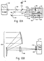
- a dichroic isolation embodiment is employed, as shown in Figs. 13A and 11B, As seen in Fig. 13A, a common Tx/Rx telescope 100 is used to define a single aperture.
- a dichroic beamsplitter 160 is used to separate a portion of the Rx signal for use as a beacon for detection by the acquisition sensor 108 and tracking sensors 126.
- a Fabry-Perot etalon 162 is used to direct the remaining Rx signal to the Rx optics.
- a fold mirror 164 received a Tx signal (differing in wavelength from the Rx signal) and directs the beam back through etalon 162 and beamsplitter 160, or through the telescope 100 toward the remote terminal.
- a common telecentric lens 166 can be used for the track detector 126, along with Rx and Tx fibers 110, 112, thereby further reducing the mass and the number of optical surfaces.
- the respective signal wavelengths are optically processed through a pair of dichroic beamsplitters 168, 170.
- two separate X-Y stages are implemented instead of a single satge 114 (see Fig. 13A).
- the present invention can also include active repositioning of the optical fibers in the Z-direction (i.e., along the optical axis) to compensate for longitudinal defocus, to actively defocus the system in an emergency situation. Also, such positioning allows a highly divergent Tx beam with a significantly enlarged field of view during the phase of signal acquisition between satellite terminals. For example, a 10 microradian beam may typically be used to communicate between terminals, but a divergence on the order of hundreds of microradians may be necessary to acquire a signal during the acquisition phase. Such change in divergence can be easily achieved by actively defocusing the fiber. This feature is also useful for compensating for mechanical fluctations that may occur in space, especially for the Rx fiber.
- the present invention significantly reduces the number of optical elements resulting in a diffraction-limited, high-optical-performance system.
- the reduced mass of the system facilitates steering of the satellite and reduces payload upon delivery, thus reducing deployment and operating expenses.
- the present optical system is much less complex, permitting a modular structure with clearly defined, independent modules.
- the present invention is more flexible, permitting precise beam steering and tracking at least one order of magnitude better than that required while preserving the required range.
- the present system is easier and less expensive to manufacture, which reduces the overall expenses associated with satellite communications.
- the present invention provides a simplified lasercom terminal with greatly improved efficiency.
- various changes in the details, materials and arrangements of parts which have been herein described and illustrated in order to explain the nature of the invention may be made by those skilled in the art within the principle and scope of the invention as expressed in the appended claims.
Landscapes
- Physics & Mathematics (AREA)
- Astronomy & Astrophysics (AREA)
- General Physics & Mathematics (AREA)
- Electromagnetism (AREA)
- Engineering & Computer Science (AREA)
- Computer Networks & Wireless Communication (AREA)
- Signal Processing (AREA)
- Optical Communication System (AREA)
- Optical Couplings Of Light Guides (AREA)
Applications Claiming Priority (2)
| Application Number | Priority Date | Filing Date | Title |
|---|---|---|---|
| US26370 | 1998-02-19 | ||
| US09/026,370 US6268944B1 (en) | 1998-02-19 | 1998-02-19 | Free-space optical lasercom system |
Publications (2)
| Publication Number | Publication Date |
|---|---|
| EP0963063A2 true EP0963063A2 (fr) | 1999-12-08 |
| EP0963063A3 EP0963063A3 (fr) | 2003-11-26 |
Family
ID=21831418
Family Applications (1)
| Application Number | Title | Priority Date | Filing Date |
|---|---|---|---|
| EP99103122A Withdrawn EP0963063A3 (fr) | 1998-02-19 | 1999-02-17 | Système à laser pour la communication optique dans l'espace libre |
Country Status (2)
| Country | Link |
|---|---|
| US (1) | US6268944B1 (fr) |
| EP (1) | EP0963063A3 (fr) |
Cited By (4)
| Publication number | Priority date | Publication date | Assignee | Title |
|---|---|---|---|---|
| EP1152555A1 (fr) * | 2000-05-03 | 2001-11-07 | Media Lario S.r.L. | Miroir de telescope pour la transmission de données optiques de grande largeur de bande dans l'espace libre |
| EP1172949A1 (fr) * | 2000-07-11 | 2002-01-16 | Media Lario S.r.L. | Méthode d'alignement automatique pour un système de communication optique en espace libre |
| ES2373535A1 (es) * | 2010-12-27 | 2012-02-06 | Universidad De Málaga | Aparato duplexor óptico para la transmisión y recepción simultánea de haces láser. |
| WO2015116730A1 (fr) | 2014-01-28 | 2015-08-06 | SA Photonics, Inc. | Suivi de communication optique dans l'espace avec compensation électronique de pointage et optique d'émission et de réception en co-pointage |
Families Citing this family (43)
| Publication number | Priority date | Publication date | Assignee | Title |
|---|---|---|---|---|
| US6868237B2 (en) | 1998-04-24 | 2005-03-15 | Lightpointe Communications, Inc. | Terrestrial optical communication network of integrated fiber and free-space links which requires no electro-optical conversion between links |
| US6239888B1 (en) * | 1998-04-24 | 2001-05-29 | Lightpointe Communications, Inc. | Terrestrial optical communication network of integrated fiber and free-space links which requires no electro-optical conversion between links |
| EP1175742A1 (fr) * | 1999-02-11 | 2002-01-30 | QuantumBeam Limited | Systeme de signalisation optique a espace libre |
| US6469815B1 (en) * | 1999-04-28 | 2002-10-22 | Trw Inc. | Inter-satellite optical link acquisition sensor |
| US6522440B1 (en) * | 1999-04-28 | 2003-02-18 | Trw Inc. | Inter-satellite optical link track sensor |
| US6957020B2 (en) * | 1999-07-07 | 2005-10-18 | Northrop Grumman Corporation | Optical inter-satellite link (OISL) gimbal |
| EP1299695A4 (fr) * | 2000-05-17 | 2003-05-28 | Coretek Inc | Monture d'objectif a cardan et ensemble d'alignement assurant un alignement optique de precision |
| US6925260B1 (en) * | 2001-03-13 | 2005-08-02 | Terabeam Corporation | Window-mounted positionable collector |
| US6801722B1 (en) * | 2001-05-01 | 2004-10-05 | Terabeam Corporation | Optical tracking system with reflective fiber |
| US20020171896A1 (en) * | 2001-05-21 | 2002-11-21 | Lightpointe Communications, Inc. | Free-space optical communication system employing wavelength conversion |
| US20030090765A1 (en) * | 2001-11-09 | 2003-05-15 | Neff Brian W. | Free-space optical communication system |
| US6856437B2 (en) * | 2002-02-01 | 2005-02-15 | Terabeam Corporation | Fast steering mirror |
| US20040208630A1 (en) * | 2002-05-14 | 2004-10-21 | Oettinger Eric G. | Method of sampling local and remote feedback in an optical wireless link |
| US20040208529A1 (en) * | 2002-05-14 | 2004-10-21 | Noxon James E. | Method of packet corruption to halt propagation in an optical wireless link |
| US7477846B2 (en) * | 2002-05-14 | 2009-01-13 | Texas Instruments Incorporated | Method of reducing control packet transmission rate for an optical wireless link |
| US7292789B1 (en) * | 2003-04-10 | 2007-11-06 | Lockheed Martin Corporation | Multi-channel wide-field laser communications method and apparatus |
| US7277641B1 (en) | 2003-05-06 | 2007-10-02 | Ball Aerospace & Technologies Corp. | Multiple access space communications optical system using a common telescope aperture |
| US7050215B1 (en) | 2003-08-01 | 2006-05-23 | Ball Aerospace & Technologies Corp. | Method and apparatus for providing a gas correlation filter for remote sensing of atmospheric trace gases |
| US7030991B1 (en) | 2003-08-01 | 2006-04-18 | Ball Aerospace & Technologies Corp. | Field condensing imaging system for remote sensing of atmospheric trace gases |
| US20050031350A1 (en) * | 2003-08-05 | 2005-02-10 | Ilan Haber | Miniature optical free space transceivers |
| US7668468B1 (en) | 2004-10-01 | 2010-02-23 | Ball Aerospace & Technologies Corp. | Numerous user laser communications optical system using chromatic waveplates and a common telescope aperture |
| US7920794B1 (en) * | 2007-01-05 | 2011-04-05 | Lockheed Martin Corporation | Free space optical communication |
| US7925167B1 (en) | 2007-10-31 | 2011-04-12 | Kozubal Marek J | Satellite downlink via patterns of uncollimated light |
| US7929125B2 (en) * | 2008-11-26 | 2011-04-19 | Raytheon Company | Gimbaled system with optical coudé path and method transferring data |
| WO2015066720A1 (fr) * | 2013-11-04 | 2015-05-07 | California Institute Of Technology | Liaisons optiques à large bande passante pour soutien de micro-satellite |
| WO2015163985A1 (fr) | 2014-04-22 | 2015-10-29 | Massachusetts Institute Of Technology | Détermination d'attitude au moyen de capteurs d'horizon terrestre infrarouges |
| US9571192B2 (en) * | 2014-05-21 | 2017-02-14 | Space Photonics, Inc. | Simultaneous multi-channel optical communications system with beam pointing, switching, and tracking using moving focal plane devices |
| US9813151B2 (en) | 2014-08-05 | 2017-11-07 | Massachusetts Institute Of Technology | Free-space optical communication module for small satellites |
| US9739571B2 (en) | 2015-01-06 | 2017-08-22 | Teledyne Scientific & Imaging, Llc | Moving object command link system and method |
| US10003402B2 (en) * | 2015-01-09 | 2018-06-19 | Massachusetts Institute Technology | Ground terminal design for high rate direct to earth optical communications |
| US10128949B2 (en) | 2015-02-27 | 2018-11-13 | Massachusetts Institute Of Technology | Methods, systems, and apparatus for global multiple-access optical communications |
| US10009107B2 (en) | 2016-08-02 | 2018-06-26 | X Development Llc | Multi-point free space optical communication system |
| US10841007B1 (en) * | 2019-12-19 | 2020-11-17 | Bae Systems Information And Electronic Systems Integration Inc. | Full duplex laser communication terminal architecture without dedicated beacon laser |
| US11411647B2 (en) | 2020-01-31 | 2022-08-09 | Com Dev Ltd. | Coarse pointing arrangement |
| US11307367B2 (en) | 2020-08-17 | 2022-04-19 | X Development Llc | Method of precision beam collimation using fiber-optic circulator and wavelength tunable source |
| US11835705B2 (en) | 2020-10-07 | 2023-12-05 | Raytheon Company | Optical sensor with Tx/Rx aperture sharing element (ASE) to block detection of the received active signal |
| US12000676B2 (en) | 2020-10-15 | 2024-06-04 | Raytheon Company | Optical sensor with Tx/Rx aperture sharing element (ASE) for processing passive and active signals |
| US11686820B2 (en) * | 2020-10-15 | 2023-06-27 | Raytheon Company | Optical sensor with ring-shaped Tx/Rx aperture sharing element (ASE) |
| US11009595B1 (en) | 2020-11-13 | 2021-05-18 | Bae Systems Information And Electronic Systems Integration Inc. | Continuously variable optical beam splitter |
| US11002956B1 (en) | 2020-11-19 | 2021-05-11 | Bae Systems Information And Electronic Systems Integration Inc. | Refractive laser communication beam director with dispersion compensation |
| US11835709B2 (en) | 2021-02-09 | 2023-12-05 | Raytheon Company | Optical sensor with micro-electro-mechanical system (MEMS) micro-mirror array (MMA) steering of the optical transmit beam |
| EP4270820B1 (fr) * | 2022-04-26 | 2024-07-31 | Airbus Defence and Space GmbH | Terminal de communication laser |
| WO2025101174A1 (fr) * | 2023-11-07 | 2025-05-15 | Viasat, Inc. | Têtes optiques doubles pour liaison de ligne d'alimentation optique dans un système de communication par satellite |
Family Cites Families (12)
| Publication number | Priority date | Publication date | Assignee | Title |
|---|---|---|---|---|
| EP0179939B1 (fr) | 1984-10-30 | 1989-02-08 | DR.-ING. RUDOLF HELL GmbH | Dispositif de transfert de lumière |
| US4662004A (en) | 1984-12-17 | 1987-04-28 | Fmw Corporation | Laser communication system |
| JP2705104B2 (ja) | 1988-05-20 | 1998-01-26 | ソニー株式会社 | 送信装置 |
| US5062150A (en) * | 1989-01-23 | 1991-10-29 | Massachusetts Institute Of Technology | Fiber-based free-space optical system |
| US5142400A (en) | 1989-12-26 | 1992-08-25 | Cubic Corporation | Method and apparatus for automatic acquisition and alignment of an optical beam communication link |
| US5060304A (en) | 1989-12-26 | 1991-10-22 | Cubic Corporation | Alignment acquiring, optical beam communication link |
| IL94308A0 (en) | 1990-05-07 | 1991-03-10 | Scitex Corp Ltd | Laser scanning apparatus |
| JP3187495B2 (ja) | 1991-12-28 | 2001-07-11 | ソニー株式会社 | 光空間伝送装置 |
| US5347387A (en) | 1992-03-24 | 1994-09-13 | Rice Robert C | Self-aligning optical transceiver |
| JP3302141B2 (ja) | 1993-11-16 | 2002-07-15 | キヤノン株式会社 | 光空間通信方法 |
| US5926594A (en) * | 1994-08-31 | 1999-07-20 | Litton Systems, Inc. | System and method for aligning and attaching optical fibers to optical waveguides, and products obtained thereby |
| US5659413A (en) * | 1995-02-28 | 1997-08-19 | The Mitre Corporation | Laser satellite communication system |
-
1998
- 1998-02-19 US US09/026,370 patent/US6268944B1/en not_active Expired - Fee Related
-
1999
- 1999-02-17 EP EP99103122A patent/EP0963063A3/fr not_active Withdrawn
Cited By (9)
| Publication number | Priority date | Publication date | Assignee | Title |
|---|---|---|---|---|
| EP1152555A1 (fr) * | 2000-05-03 | 2001-11-07 | Media Lario S.r.L. | Miroir de telescope pour la transmission de données optiques de grande largeur de bande dans l'espace libre |
| WO2001084747A3 (fr) * | 2000-05-03 | 2003-05-15 | Media Lario Srl | Miroir de telescope pour transmission optique de donnees dans l'espace a haute largeur de bande |
| EP1172949A1 (fr) * | 2000-07-11 | 2002-01-16 | Media Lario S.r.L. | Méthode d'alignement automatique pour un système de communication optique en espace libre |
| WO2002005460A1 (fr) * | 2000-07-11 | 2002-01-17 | Media Lario S.R.L. | Procede de poursuite automatique pour systeme de communication optique dans l'espace libre |
| ES2373535A1 (es) * | 2010-12-27 | 2012-02-06 | Universidad De Málaga | Aparato duplexor óptico para la transmisión y recepción simultánea de haces láser. |
| WO2012089862A1 (fr) * | 2010-12-27 | 2012-07-05 | Universidad De Málaga | Appareil duplexeur optique pour l'émission et la réception simultanées de faisceaux laser |
| WO2015116730A1 (fr) | 2014-01-28 | 2015-08-06 | SA Photonics, Inc. | Suivi de communication optique dans l'espace avec compensation électronique de pointage et optique d'émission et de réception en co-pointage |
| EP3100378A4 (fr) * | 2014-01-28 | 2017-09-20 | Sa Photonics, Inc. | Suivi de communication optique dans l'espace avec compensation électronique de pointage et optique d'émission et de réception en co-pointage |
| US9876567B2 (en) | 2014-01-28 | 2018-01-23 | SA Photonics, Inc. | Free space optical communication tracking with electronic boresight compensation and co-boresighted transmit and receive optics |
Also Published As
| Publication number | Publication date |
|---|---|
| EP0963063A3 (fr) | 2003-11-26 |
| US6268944B1 (en) | 2001-07-31 |
Similar Documents
| Publication | Publication Date | Title |
|---|---|---|
| US6268944B1 (en) | Free-space optical lasercom system | |
| EP0607906B1 (fr) | Système de réglage d'alignement pour l'utilisation dans un système d'émetteur-récepteur optique | |
| US7397981B2 (en) | Apparatus and method of compensating for wavelength dispersion of optical transmission line | |
| EP0977070B1 (fr) | Téléscope avec un chemin optique commun pour un terminal optique de communication | |
| US10859348B1 (en) | System for active telescope alignment, focus and beam control | |
| WO2022031855A1 (fr) | Terminal de communication optique à espace libre avec composant optique dispersif, système actionneur ou système de relais optique | |
| US9973274B1 (en) | Fast tracking free space optical module | |
| EP0903608A2 (fr) | Dispositif pour le guidage d'un faisceau | |
| Swanson et al. | Using fiber optics to simplify free-space lasercom systems | |
| US11409089B2 (en) | Optical apparatus | |
| CN114754984A (zh) | 折反式光瞳光轴传感器 | |
| JP2005530174A (ja) | マルチ光学チャンネル | |
| AU2020219446B2 (en) | Injection of a beam of radiation into an optical fibre | |
| US11409099B2 (en) | Optical apparatus | |
| JP2006050100A (ja) | 空間光通信装置 | |
| JP2006023626A (ja) | コリメーション調整機構、それを用いた光アンテナ装置およびコリメーション調整方法 | |
| US6317533B1 (en) | Fiber optic switch configurations | |
| US11644542B2 (en) | Optical sensor with MEMS MMA steered transmitter and staring detector | |
| JP4500894B2 (ja) | 空間光通信装置 | |
| Page | Design of the Optical Communication Demonstrator instrument optical system | |
| EP4686656A1 (fr) | Télescope optique et système de terminal optique comprenant le télescope | |
| RU2328077C1 (ru) | Устройство двухсторонней оптической связи | |
| EP4564708A1 (fr) | Terminal optique et procédé de communication quantique | |
| WO2026027782A1 (fr) | Télescope optique et système de terminal optique comprenant le télescope | |
| Czichy et al. | Diffractive optics for advanced free space laser communication terminals |
Legal Events
| Date | Code | Title | Description |
|---|---|---|---|
| PUAI | Public reference made under article 153(3) epc to a published international application that has entered the european phase |
Free format text: ORIGINAL CODE: 0009012 |
|
| AK | Designated contracting states |
Kind code of ref document: A2 Designated state(s): AT BE CH CY DE DK ES FI FR GB GR IE IT LI LU MC NL PT SE |
|
| AX | Request for extension of the european patent |
Free format text: AL;LT;LV;MK;RO;SI |
|
| PUAL | Search report despatched |
Free format text: ORIGINAL CODE: 0009013 |
|
| AK | Designated contracting states |
Kind code of ref document: A3 Designated state(s): AT BE CH CY DE DK ES FI FR GB GR IE IT LI LU MC NL PT SE |
|
| AX | Request for extension of the european patent |
Extension state: AL LT LV MK RO SI |
|
| AKX | Designation fees paid | ||
| REG | Reference to a national code |
Ref country code: DE Ref legal event code: 8566 |
|
| STAA | Information on the status of an ep patent application or granted ep patent |
Free format text: STATUS: THE APPLICATION IS DEEMED TO BE WITHDRAWN |
|
| 18D | Application deemed to be withdrawn |
Effective date: 20040527 |