EP0963141A2 - Dispositif pour la génération de plasma - Google Patents
Dispositif pour la génération de plasma Download PDFInfo
- Publication number
- EP0963141A2 EP0963141A2 EP99105216A EP99105216A EP0963141A2 EP 0963141 A2 EP0963141 A2 EP 0963141A2 EP 99105216 A EP99105216 A EP 99105216A EP 99105216 A EP99105216 A EP 99105216A EP 0963141 A2 EP0963141 A2 EP 0963141A2
- Authority
- EP
- European Patent Office
- Prior art keywords
- conductor
- rod
- insulating tube
- cap
- shaped conductor
- Prior art date
- Legal status (The legal status is an assumption and is not a legal conclusion. Google has not performed a legal analysis and makes no representation as to the accuracy of the status listed.)
- Granted
Links
- 239000004020 conductor Substances 0.000 claims abstract description 47
- 230000005672 electromagnetic field Effects 0.000 claims abstract description 5
- 239000011810 insulating material Substances 0.000 claims abstract description 3
- 210000002381 plasma Anatomy 0.000 description 20
- 238000000034 method Methods 0.000 description 10
- 239000011521 glass Substances 0.000 description 5
- 239000011248 coating agent Substances 0.000 description 4
- 238000000576 coating method Methods 0.000 description 4
- 238000013016 damping Methods 0.000 description 3
- MCMNRKCIXSYSNV-UHFFFAOYSA-N Zirconium dioxide Chemical compound O=[Zr]=O MCMNRKCIXSYSNV-UHFFFAOYSA-N 0.000 description 2
- 229910052751 metal Inorganic materials 0.000 description 2
- 239000002184 metal Substances 0.000 description 2
- VYPSYNLAJGMNEJ-UHFFFAOYSA-N Silicium dioxide Chemical compound O=[Si]=O VYPSYNLAJGMNEJ-UHFFFAOYSA-N 0.000 description 1
- 238000010521 absorption reaction Methods 0.000 description 1
- 239000000919 ceramic Substances 0.000 description 1
- 230000007423 decrease Effects 0.000 description 1
- 239000003989 dielectric material Substances 0.000 description 1
- 230000000694 effects Effects 0.000 description 1
- 238000005516 engineering process Methods 0.000 description 1
- 238000012423 maintenance Methods 0.000 description 1
- 239000000463 material Substances 0.000 description 1
- 229910052574 oxide ceramic Inorganic materials 0.000 description 1
- 239000011224 oxide ceramic Substances 0.000 description 1
- TWNQGVIAIRXVLR-UHFFFAOYSA-N oxo(oxoalumanyloxy)alumane Chemical compound O=[Al]O[Al]=O TWNQGVIAIRXVLR-UHFFFAOYSA-N 0.000 description 1
- 230000035515 penetration Effects 0.000 description 1
- 238000009420 retrofitting Methods 0.000 description 1
- 125000006850 spacer group Chemical group 0.000 description 1
- 239000000758 substrate Substances 0.000 description 1
- 238000004381 surface treatment Methods 0.000 description 1
- XLYOFNOQVPJJNP-UHFFFAOYSA-N water Substances O XLYOFNOQVPJJNP-UHFFFAOYSA-N 0.000 description 1
Images
Classifications
-
- H—ELECTRICITY
- H01—ELECTRIC ELEMENTS
- H01J—ELECTRIC DISCHARGE TUBES OR DISCHARGE LAMPS
- H01J37/00—Discharge tubes with provision for introducing objects or material to be exposed to the discharge, e.g. for the purpose of examination or processing thereof
- H01J37/32—Gas-filled discharge tubes
- H01J37/32009—Arrangements for generation of plasma specially adapted for examination or treatment of objects, e.g. plasma sources
- H01J37/32192—Microwave generated discharge
- H01J37/32211—Means for coupling power to the plasma
- H01J37/3222—Antennas
-
- H—ELECTRICITY
- H01—ELECTRIC ELEMENTS
- H01J—ELECTRIC DISCHARGE TUBES OR DISCHARGE LAMPS
- H01J37/00—Discharge tubes with provision for introducing objects or material to be exposed to the discharge, e.g. for the purpose of examination or processing thereof
- H01J37/32—Gas-filled discharge tubes
- H01J37/32009—Arrangements for generation of plasma specially adapted for examination or treatment of objects, e.g. plasma sources
- H01J37/32192—Microwave generated discharge
-
- H—ELECTRICITY
- H05—ELECTRIC TECHNIQUES NOT OTHERWISE PROVIDED FOR
- H05H—PLASMA TECHNIQUE; PRODUCTION OF ACCELERATED ELECTRICALLY-CHARGED PARTICLES OR OF NEUTRONS; PRODUCTION OR ACCELERATION OF NEUTRAL MOLECULAR OR ATOMIC BEAMS
- H05H1/00—Generating plasma; Handling plasma
- H05H1/24—Generating plasma
- H05H1/46—Generating plasma using applied electromagnetic fields, e.g. high frequency or microwave energy
-
- H—ELECTRICITY
- H05—ELECTRIC TECHNIQUES NOT OTHERWISE PROVIDED FOR
- H05H—PLASMA TECHNIQUE; PRODUCTION OF ACCELERATED ELECTRICALLY-CHARGED PARTICLES OR OF NEUTRONS; PRODUCTION OR ACCELERATION OF NEUTRAL MOLECULAR OR ATOMIC BEAMS
- H05H1/00—Generating plasma; Handling plasma
- H05H1/24—Generating plasma
- H05H1/46—Generating plasma using applied electromagnetic fields, e.g. high frequency or microwave energy
- H05H1/461—Microwave discharges
- H05H1/463—Microwave discharges using antennas or applicators
Definitions
- the invention relates to a device for generating of plasma in a vacuum chamber with the help of alternating electromagnetic fields at which a rod-shaped conductor inside a tube insulating material into the vacuum chamber is, the inner diameter of the insulating tube larger than the diameter of the conductor is and the insulating tube at one end in the wall held in the vacuum chamber and against it its outer surface is sealed and the conductor to a source for generating the electromagnetic AC field is connected.
- a known device for generating plasma (DE 195 03 205) allows in a limited Operating area (process area, gas pressure, microwave power) Plasmas for surface treatments and to produce coating technology.
- the well-known Device essentially consists of a cylindrical installed in a vacuum process chamber Glass tube and one inside Metallic conductive tube, the interior of the Glass tube atmospheric pressure prevails.
- Microwave power is on both sides by two feeds and two metallic coaxial lines from inner conductor and outer conductor, through the walls initiated the vacuum process chamber.
- the missing one Outer conductor of the coaxial line within the vacuum process chamber is replaced by a plasma discharge, those with sufficient ignition conditions (Gas pressure) ignited by the microwave power and is maintained, the microwave power from the two metallic coaxial lines and through the glass tube into the vacuum process chamber can leak.
- the plasma surrounds it cylindrical glass tube from the outside and forms together with the inner conductor using a coaxial line very high damping coating.
- microwave power fed in on both sides the gas pressure of the vacuum process chamber is set in this way be that the plasma is apparently even burns along the device where inside the vacuum process chamber of the outer conductor of the coaxial line is missing.
- the attenuation of the microwaves does not depend in any way from the position along the coaxial line.
- the dielectric filling of the coaxial line There is air and the relative dielectric constant of the dielectric of the coaxial line the length of the device is constant depends on the Amount of damping only from the penetration depth of the Microwaves into the conductive surfaces. At constant damping per unit length means that that the net delivered to the plasma per unit length Microwave power along the device sinks towards the middle. Because the outer conductor If there is plasma, this conductivity cannot be exact be determined. Certainly it depends on the Plasma density decreases and this in turn is specific Limits a function of the microwave power density in the discharge area. It is probably some orders of magnitude higher than metallic ones Surfaces ( ⁇ 50 ⁇ m) and not constant over the length of the device.
- the known device is hardly able to maintain a plasma discharge at pressures lower than 8x10 -2 mbar.
- the present invention is based on the object the disadvantages of the known device improve and also train so that them for coating larger, plan and three-dimensional substrates is suitable and only each have an opening in the wall of the vacuum chamber is needed.
- this object is achieved by that in the from the rod-shaped conductor and the Insulating tube formed a tubular Conductor extends coaxially to the rod-shaped conductor, the between the rod-shaped conductor and the tubular conductor formed, radially inner Annular gap corresponds to the waveguide of the source and that of the insulating tube and the tubular Conductor formed radially outer annular gap with the Waveguide connected to a second source stands.
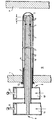
- the invention allows a wide variety of design options to; one of them is in the attached Drawing purely schematic and in longitudinal section shown in more detail.
- the device consists essentially of the passed through the wall part 1 of the vacuum chamber 13 Insulating tube 2 (a glass tube) with a to this coaxially arranged rod-shaped conductor 3, one end of which is connected to the rectangular waveguide 10 the source 9 is firmly connected, a tubular Head 4, which is coaxial to the rod-shaped Conductor 3 in the insulating tube 2 and the rod-shaped Head 3 formed annular gap, one Spacer ring 5, which ensures that the Annular gap 14 is maintained and for example is made of a plastic, one Deflection cap 6, the annular gaps 14 and 15 with each other connects a metal sleeve 7, which in the insulating tube 2 is inserted and an outer conductor forms one between the insulating tube 2 and the chamber wall 1 inserted round cord ring 12, which is firmly connected to the metal sleeve 7 Rectangular waveguide 10 'of a source 8 and in the rectangular waveguides 10, 10 'slidably arranged Tuning members 11, 11 '.
- the supply of microwave power to the device does not necessarily have to be via rectangular waveguides but can also be done via other suitable Waveguide devices are made. Also the device must have two waveguide devices supplied microwaves are not to be phase-correlated.
- the length of the entire device can be adjusted to that respective application can be adapted, in particular for very long versions, for stability reasons a disc 5 made of dielectric material provided with low microwave absorption to the coaxial conductors 3, 4 and 7 in keep concentric shape.
- the entire device is inside a container made of a vacuum-tight, heat-resistant, but microwave-permeable material (e.g. low-water quartz glass, aluminum oxide ceramic, Zirconia ceramic), being in the device Atmospheric pressure prevails and outside the Isolierrohres 2 a gas pressure, which is used for the ignition and maintenance of a plasma discharge is.
- the insulating tube 2 is only in one place through the wall 1 of a vacuum container (e.g. Plasma process reactor) 13 and vacuum-tight with this connected.
Landscapes
- Physics & Mathematics (AREA)
- Engineering & Computer Science (AREA)
- Plasma & Fusion (AREA)
- Chemical & Material Sciences (AREA)
- Analytical Chemistry (AREA)
- Electromagnetism (AREA)
- Spectroscopy & Molecular Physics (AREA)
- Plasma Technology (AREA)
- Chemical Vapour Deposition (AREA)
Applications Claiming Priority (3)
| Application Number | Priority Date | Filing Date | Title |
|---|---|---|---|
| DE19825125 | 1998-06-05 | ||
| DE19825125A DE19825125A1 (de) | 1998-06-05 | 1998-06-05 | Vorrichtung zur Erzeugung von Plasma |
| US09/315,032 US6175183B1 (en) | 1998-06-05 | 1999-05-20 | Device for producing plasma |
Publications (3)
| Publication Number | Publication Date |
|---|---|
| EP0963141A2 true EP0963141A2 (fr) | 1999-12-08 |
| EP0963141A3 EP0963141A3 (fr) | 2003-11-05 |
| EP0963141B1 EP0963141B1 (fr) | 2010-06-16 |
Family
ID=26046638
Family Applications (1)
| Application Number | Title | Priority Date | Filing Date |
|---|---|---|---|
| EP99105216A Expired - Lifetime EP0963141B1 (fr) | 1998-06-05 | 1999-03-13 | Dispositif pour la génération de plasma |
Country Status (4)
| Country | Link |
|---|---|
| US (1) | US6175183B1 (fr) |
| EP (1) | EP0963141B1 (fr) |
| JP (1) | JP4440371B2 (fr) |
| DE (1) | DE19825125A1 (fr) |
Cited By (2)
| Publication number | Priority date | Publication date | Assignee | Title |
|---|---|---|---|---|
| EP1780303A3 (fr) * | 2005-11-01 | 2010-07-07 | Applied Materials, Inc. | Appareillage et procédé d'augmentation de la puissance de sources de décharge linéaires micro-ondes |
| CN109494651A (zh) * | 2018-10-08 | 2019-03-19 | 沈阳世杰电器有限公司 | 复合绝缘高温穿墙套管装置 |
Families Citing this family (6)
| Publication number | Priority date | Publication date | Assignee | Title |
|---|---|---|---|---|
| DE19726663A1 (de) * | 1997-06-23 | 1999-01-28 | Sung Spitzl Hildegard Dr Ing | Vorrichtung zur Erzeugung von homogenen Mikrowellenplasmen |
| DE102004039468B4 (de) * | 2004-08-14 | 2008-09-25 | R3T Gmbh Rapid Reactive Radicals Technology | Vorrichtung zur Erzeugung angeregter und/oder ionisierter Teilchen in einem Plasma |
| KR100689037B1 (ko) * | 2005-08-24 | 2007-03-08 | 삼성전자주식회사 | 마이크로파 공명 플라즈마 발생장치 및 그것을 구비하는플라즈마 처리 시스템 |
| JP5150053B2 (ja) * | 2006-02-03 | 2013-02-20 | 株式会社日立ハイテクノロジーズ | プラズマ処理装置 |
| DE102008036766B4 (de) | 2008-08-07 | 2013-08-01 | Alexander Gschwandtner | Vorrichtung und Verfahren zum Erzeugen dielektrischer Schichten im Mikrowellenplasma |
| EP2673564B8 (fr) * | 2011-02-10 | 2024-03-13 | Plasma Tech Holdings, LLC | Procédé de fonctionnement d'un cubilot à plasma inductif à bain |
Family Cites Families (9)
| Publication number | Priority date | Publication date | Assignee | Title |
|---|---|---|---|---|
| JPS55131175A (en) * | 1979-03-30 | 1980-10-11 | Toshiba Corp | Surface treatment apparatus with microwave plasma |
| US4517495A (en) * | 1982-09-21 | 1985-05-14 | Piepmeier Edward H | Multi-electrode plasma source |
| US4974487A (en) * | 1984-10-05 | 1990-12-04 | Gt-Devices | Plasma propulsion apparatus and method |
| US4566403A (en) * | 1985-01-30 | 1986-01-28 | Sovonics Solar Systems | Apparatus for microwave glow discharge deposition |
| JPH01184921A (ja) * | 1988-01-20 | 1989-07-24 | Canon Inc | エッチング、アッシング及び成膜等に有用なプラズマ処理装置 |
| DE4136297A1 (de) * | 1991-11-04 | 1993-05-06 | Plasma Electronic Gmbh, 7024 Filderstadt, De | Vorrichtung zur lokalen erzeugung eines plasmas in einer behandlungskammer mittels mikrowellenanregung |
| US5361016A (en) * | 1992-03-26 | 1994-11-01 | General Atomics | High density plasma formation using whistler mode excitation in a reduced cross-sectional area formation tube |
| DE19503205C1 (de) * | 1995-02-02 | 1996-07-11 | Muegge Electronic Gmbh | Vorrichtung zur Erzeugung von Plasma |
| DE19532435C2 (de) * | 1995-09-02 | 2001-07-19 | Ver Foerderung Inst Kunststoff | Vorrichtung und Verfahren zum Erzeugen eines Plasmas |
-
1998
- 1998-06-05 DE DE19825125A patent/DE19825125A1/de not_active Withdrawn
-
1999
- 1999-03-13 EP EP99105216A patent/EP0963141B1/fr not_active Expired - Lifetime
- 1999-05-20 US US09/315,032 patent/US6175183B1/en not_active Expired - Lifetime
- 1999-06-02 JP JP15536899A patent/JP4440371B2/ja not_active Expired - Lifetime
Cited By (3)
| Publication number | Priority date | Publication date | Assignee | Title |
|---|---|---|---|---|
| EP1780303A3 (fr) * | 2005-11-01 | 2010-07-07 | Applied Materials, Inc. | Appareillage et procédé d'augmentation de la puissance de sources de décharge linéaires micro-ondes |
| CN109494651A (zh) * | 2018-10-08 | 2019-03-19 | 沈阳世杰电器有限公司 | 复合绝缘高温穿墙套管装置 |
| CN109494651B (zh) * | 2018-10-08 | 2023-06-30 | 沈阳世杰电器有限公司 | 复合绝缘高温穿墙套管装置 |
Also Published As
| Publication number | Publication date |
|---|---|
| US6175183B1 (en) | 2001-01-16 |
| DE19825125A1 (de) | 1999-12-09 |
| EP0963141A3 (fr) | 2003-11-05 |
| EP0963141B1 (fr) | 2010-06-16 |
| JPH11354291A (ja) | 1999-12-24 |
| JP4440371B2 (ja) | 2010-03-24 |
Similar Documents
| Publication | Publication Date | Title |
|---|---|---|
| EP0916153B1 (fr) | Dispositif pour la production de plasma | |
| DE19963122A1 (de) | Anordnung zum Einkoppeln von Mikrowellenenergie in eine Behandlungskammer | |
| EP0522300A2 (fr) | Dispositif pour coupler de l'énergie micro-onde | |
| DE102010027619B3 (de) | Mikrowellenplasmaquelle mit einer Vorrichtung zur Zuführung von Mikrowellenenergie | |
| DE4340224A1 (de) | Einrichtung zum Erzeugen von Plasma mittels Mikrowellenstrahlung | |
| EP1415321A1 (fr) | Dispositif pour munir des objets d'un revetement | |
| DE1955914A1 (de) | Hochfrequenz-Plasmagenerator | |
| EP1994807A1 (fr) | Dispositif de production d'un jet de plasma | |
| EP1183709B1 (fr) | Dispositif a dilatation lineaire destine au traitement micro-ondes de grande surface et a la production de plasma grande surface | |
| EP0961528B1 (fr) | Dispositif pour la génération de plasma | |
| EP0963141A2 (fr) | Dispositif pour la génération de plasma | |
| DE1514402B2 (de) | Beruehrungssichere ionisierungs luftduese | |
| EP1088335B1 (fr) | Lampe a decharge comportant un culot | |
| EP2796840B1 (fr) | Convertisseur de modes pour un radar de niveau de remplissage | |
| EP1334510B1 (fr) | Lampe a decharge a barriere dielectrique | |
| DE3235874C2 (de) | Ladungsableiter für eine Rohrleitung | |
| DE3214487C2 (fr) | ||
| WO2004042872A1 (fr) | Vis de contact | |
| DE853017C (de) | UEbergang zwischen einem wendelfoermigen Wellenleiter und einer Lecherleitung | |
| EP1900493B1 (fr) | Procédé destiné à la modification de surfaces intérieures des corps creux tubulaires au moyen d'un plasma, et système mettant en oeuvre ledit procédé | |
| DE19848022A1 (de) | Vorrichtung zur Erzeugung von Plasma | |
| DE3540536C2 (fr) | ||
| DE102014119455A1 (de) | Gehäuse für ein Feldgerät der Automatisierungstechnik | |
| EP2381228B1 (fr) | Sonde de mesure dotée d'un dispositif de protection contre un support de mesure et procédé de fabrication d'une telle sonde de mesure | |
| DE102006034084B4 (de) | Anordnung zur Konzentration von Mikrowellenenergie |
Legal Events
| Date | Code | Title | Description |
|---|---|---|---|
| PUAI | Public reference made under article 153(3) epc to a published international application that has entered the european phase |
Free format text: ORIGINAL CODE: 0009012 |
|
| AK | Designated contracting states |
Kind code of ref document: A2 Designated state(s): AT BE CH CY DE DK ES FI FR GB GR IE IT LI LU MC NL PT SE |
|
| AX | Request for extension of the european patent |
Free format text: AL;LT;LV;MK;RO;SI |
|
| PUAL | Search report despatched |
Free format text: ORIGINAL CODE: 0009013 |
|
| AK | Designated contracting states |
Kind code of ref document: A3 Designated state(s): AT BE CH CY DE DK ES FI FR GB GR IE IT LI LU MC NL PT SE |
|
| AX | Request for extension of the european patent |
Extension state: AL LT LV MK RO SI |
|
| RAP1 | Party data changed (applicant data changed or rights of an application transferred) |
Owner name: UNAXIS DEUTSCHLAND HOLDING GMBH |
|
| RAP1 | Party data changed (applicant data changed or rights of an application transferred) |
Owner name: UNAXIS DEUTSCHLAND HOLDING GMBH |
|
| 17P | Request for examination filed |
Effective date: 20040419 |
|
| AKX | Designation fees paid |
Designated state(s): BE DE FR GB NL |
|
| RAP1 | Party data changed (applicant data changed or rights of an application transferred) |
Owner name: UNAXIS DEUTSCHLAND HOLDING GMBH |
|
| RAP1 | Party data changed (applicant data changed or rights of an application transferred) |
Owner name: OERLIKON DEUTSCHLAND HOLDING GMBH |
|
| 17Q | First examination report despatched |
Effective date: 20081222 |
|
| RAP1 | Party data changed (applicant data changed or rights of an application transferred) |
Owner name: OERLIKON DEUTSCHLAND HOLDING GMBH |
|
| GRAP | Despatch of communication of intention to grant a patent |
Free format text: ORIGINAL CODE: EPIDOSNIGR1 |
|
| GRAS | Grant fee paid |
Free format text: ORIGINAL CODE: EPIDOSNIGR3 |
|
| GRAA | (expected) grant |
Free format text: ORIGINAL CODE: 0009210 |
|
| AK | Designated contracting states |
Kind code of ref document: B1 Designated state(s): BE DE FR GB NL |
|
| REF | Corresponds to: |
Ref document number: 59915176 Country of ref document: DE Date of ref document: 20100729 Kind code of ref document: P |
|
| REG | Reference to a national code |
Ref country code: NL Ref legal event code: VDEP Effective date: 20100616 |
|
| PG25 | Lapsed in a contracting state [announced via postgrant information from national office to epo] |
Ref country code: NL Free format text: LAPSE BECAUSE OF FAILURE TO SUBMIT A TRANSLATION OF THE DESCRIPTION OR TO PAY THE FEE WITHIN THE PRESCRIBED TIME-LIMIT Effective date: 20100616 |
|
| PLBE | No opposition filed within time limit |
Free format text: ORIGINAL CODE: 0009261 |
|
| STAA | Information on the status of an ep patent application or granted ep patent |
Free format text: STATUS: NO OPPOSITION FILED WITHIN TIME LIMIT |
|
| 26N | No opposition filed |
Effective date: 20110317 |
|
| REG | Reference to a national code |
Ref country code: DE Ref legal event code: R097 Ref document number: 59915176 Country of ref document: DE Effective date: 20110316 |
|
| BERE | Be: lapsed |
Owner name: OERLIKON DEUTSCHLAND HOLDING G.M.B.H. Effective date: 20110331 |
|
| GBPC | Gb: european patent ceased through non-payment of renewal fee |
Effective date: 20110313 |
|
| PG25 | Lapsed in a contracting state [announced via postgrant information from national office to epo] |
Ref country code: BE Free format text: LAPSE BECAUSE OF NON-PAYMENT OF DUE FEES Effective date: 20110331 |
|
| PG25 | Lapsed in a contracting state [announced via postgrant information from national office to epo] |
Ref country code: GB Free format text: LAPSE BECAUSE OF NON-PAYMENT OF DUE FEES Effective date: 20110313 |
|
| REG | Reference to a national code |
Ref country code: FR Ref legal event code: PLFP Year of fee payment: 18 |
|
| REG | Reference to a national code |
Ref country code: FR Ref legal event code: PLFP Year of fee payment: 19 |
|
| REG | Reference to a national code |
Ref country code: FR Ref legal event code: PLFP Year of fee payment: 20 |
|
| PGFP | Annual fee paid to national office [announced via postgrant information from national office to epo] |
Ref country code: DE Payment date: 20180322 Year of fee payment: 20 |
|
| PGFP | Annual fee paid to national office [announced via postgrant information from national office to epo] |
Ref country code: FR Payment date: 20180323 Year of fee payment: 20 |
|
| REG | Reference to a national code |
Ref country code: DE Ref legal event code: R071 Ref document number: 59915176 Country of ref document: DE |