EP0963174B1 - Procede de localisation d'un objet dans un milieu trouble - Google Patents
Procede de localisation d'un objet dans un milieu trouble Download PDFInfo
- Publication number
- EP0963174B1 EP0963174B1 EP98950253A EP98950253A EP0963174B1 EP 0963174 B1 EP0963174 B1 EP 0963174B1 EP 98950253 A EP98950253 A EP 98950253A EP 98950253 A EP98950253 A EP 98950253A EP 0963174 B1 EP0963174 B1 EP 0963174B1
- Authority
- EP
- European Patent Office
- Prior art keywords
- medium
- light path
- intensity
- turbid medium
- intensities
- Prior art date
- Legal status (The legal status is an assumption and is not a legal conclusion. Google has not performed a legal analysis and makes no representation as to the accuracy of the status listed.)
- Expired - Lifetime
Links
- 238000000034 method Methods 0.000 title claims description 29
- 238000012937 correction Methods 0.000 claims description 15
- 230000001678 irradiating effect Effects 0.000 claims description 3
- 230000008878 coupling Effects 0.000 claims 2
- 238000010168 coupling process Methods 0.000 claims 2
- 238000005859 coupling reaction Methods 0.000 claims 2
- 238000003384 imaging method Methods 0.000 claims 1
- 210000000481 breast Anatomy 0.000 description 29
- 238000005259 measurement Methods 0.000 description 12
- 230000003287 optical effect Effects 0.000 description 10
- 239000004020 conductor Substances 0.000 description 6
- 238000010521 absorption reaction Methods 0.000 description 5
- 239000011159 matrix material Substances 0.000 description 5
- 230000000694 effects Effects 0.000 description 4
- 230000006870 function Effects 0.000 description 4
- 229940028435 intralipid Drugs 0.000 description 4
- 241001465754 Metazoa Species 0.000 description 3
- 238000012886 linear function Methods 0.000 description 3
- 239000007788 liquid Substances 0.000 description 3
- 238000009607 mammography Methods 0.000 description 3
- 238000004364 calculation method Methods 0.000 description 2
- 238000001727 in vivo Methods 0.000 description 2
- 230000035945 sensitivity Effects 0.000 description 2
- 201000009030 Carcinoma Diseases 0.000 description 1
- 206010028980 Neoplasm Diseases 0.000 description 1
- 238000000149 argon plasma sintering Methods 0.000 description 1
- 201000011510 cancer Diseases 0.000 description 1
- 238000001514 detection method Methods 0.000 description 1
- 230000005670 electromagnetic radiation Effects 0.000 description 1
- 238000003331 infrared imaging Methods 0.000 description 1
- 230000005865 ionizing radiation Effects 0.000 description 1
- 238000012417 linear regression Methods 0.000 description 1
- 230000004807 localization Effects 0.000 description 1
- 239000000463 material Substances 0.000 description 1
- 238000010606 normalization Methods 0.000 description 1
- 239000004065 semiconductor Substances 0.000 description 1
- 239000000126 substance Substances 0.000 description 1
- 238000003325 tomography Methods 0.000 description 1
- 230000007704 transition Effects 0.000 description 1
Images


Classifications
-
- A—HUMAN NECESSITIES
- A61—MEDICAL OR VETERINARY SCIENCE; HYGIENE
- A61B—DIAGNOSIS; SURGERY; IDENTIFICATION
- A61B5/00—Measuring for diagnostic purposes; Identification of persons
- A61B5/0059—Measuring for diagnostic purposes; Identification of persons using light, e.g. diagnosis by transillumination, diascopy, fluorescence
- A61B5/0082—Measuring for diagnostic purposes; Identification of persons using light, e.g. diagnosis by transillumination, diascopy, fluorescence adapted for particular medical purposes
- A61B5/0091—Measuring for diagnostic purposes; Identification of persons using light, e.g. diagnosis by transillumination, diascopy, fluorescence adapted for particular medical purposes for mammography
-
- A—HUMAN NECESSITIES
- A61—MEDICAL OR VETERINARY SCIENCE; HYGIENE
- A61B—DIAGNOSIS; SURGERY; IDENTIFICATION
- A61B5/00—Measuring for diagnostic purposes; Identification of persons
- A61B5/43—Detecting, measuring or recording for evaluating the reproductive systems
- A61B5/4306—Detecting, measuring or recording for evaluating the reproductive systems for evaluating the female reproductive systems, e.g. gynaecological evaluations
- A61B5/4312—Breast evaluation or disorder diagnosis
-
- G—PHYSICS
- G01—MEASURING; TESTING
- G01N—INVESTIGATING OR ANALYSING MATERIALS BY DETERMINING THEIR CHEMICAL OR PHYSICAL PROPERTIES
- G01N21/00—Investigating or analysing materials by the use of optical means, i.e. using sub-millimetre waves, infrared, visible or ultraviolet light
- G01N21/17—Systems in which incident light is modified in accordance with the properties of the material investigated
- G01N21/47—Scattering, i.e. diffuse reflection
- G01N21/4795—Scattering, i.e. diffuse reflection spatially resolved investigating of object in scattering medium
Definitions
- the invention relates to a method of localizing an object in a turbid medium, which method includes the following steps:
- the invention also relates to a device for carrying out a method of this kind.
- light is to be understood to mean electromagnetic radiation of a wavelength in the range of from 400 to 1400 nm.
- a turbid medium is to be understood to mean a substance consisting of a material having a high light scattering coefficient. Examples in this respect are an Intralipid solution or biological tissue.
- a method of this kind is described in patent application EP 97202187.7.
- the known method can be used for in vivo breast examinations to determine the presence of tumors in breast tissue of a human or animal female.
- an attenuation coefficient of the calibration medium is made equal to a predetermined mean attenuation coefficient of the breast tissue. This can be achieved, for example by choosing a calibration medium in the form of a liquid with a solution of, for example Intralipid, having an attenuation coefficient which is equal to the predetermined mean attenuation coefficient of the breast tissue.
- Another possibility is to add a dye to the liquid with the dissolved Intralipid with a predetermined fixed percentage, and to detune the wavelength of the light to be generated by the light source in such a manner that the attenuation coefficient of the calibration medium is equal to the predetermined mean attenuation coefficient of the breast tissue. Furthermore, in order to prevent artefacts in the reconstructed image which are due to transitions between the calibration medium and an environment of the calibration medium, the measured intensities are normalized.
- the method according to the invention includes a step for performing a correction on the normalized intensities in which a corrected intensity of a light path to be selected is determined by a combination of the normalized intensity of the selected light path, the normalized intensities, lengths of the light paths and a length of the selected light path.
- the invention is based on the recognition of the fact that in an infinite medium for a first order approximation for a selected light path having a length r and an intensity I ijk a first attenuation coefficient K 1 of a calibration medium can be recalculated to an intensity I ref associated with a second attenuation coefficient K 2 of the reference medium. Furthermore, if the intensities for a given K, of a calibration medium are known, source strengths and photodetector sensitivities are also defined, so that artefacts in the reconstructed image which are caused by a change of the intensity of a light source to be used or by a change of the sensitivity of a photodetector are counteracted.
- edge effects which occur between the calibration medium and the turbid medium or the edge effects which occur between the calibration medium and a holder containing the calibration medium and the turbid medium will change in a predictable manner when the attenuation coefficient K of the calibration medium varies, so that the edge effects can be compensated after the reconstruction.
- a further advantage consists in that in order to perform the correction, a calibration measurement need be determined only once so as to determine the intensities associated with the light paths in the calibration medium. This calibration is subsequently used to determine the corrections of the normalized intensities for all subsequent measurements performed by means of the same device on different human or animal bodies while using of the formula in which r is the length of a selected light path between a light source and a photodetector.
- a special version of the method according to the invention is characterized in that a value of the combination comprises a function of the length of the selected light path and a derivative of the normalized intensity to the length of the light path.
- the derivative constitutes an estimate of the difference K 2 -K 1 .
- the derivative is equal to a direction coefficient of a reference line representing the logarithm of the ratio of the measured intensity of the calibration medium to the measured intensity of the reference medium as a linear function a 1 .r of the selected light path, a first order parameter a 1 of which corresponds to an estimate of the difference K 2 -K 1 between the attenuation coefficients of the calibration medium and the reference medium, respectively.
- a further version of the method according to the invention is characterized in that the normalized intensity of a light path to be selected is determined by a logarithm of a ratio of a first intensity of a selected light path in the turbid medium and the calibration medium to a second intensity of the selected light path in the calibration medium.
- the corrected intensity I" for a light path to be selected is determined from the measured intensity in conformity with the formula in which I measurement represents the measured intensity of the selected light path in the turbid medium and the calibration medium, I cal represents the measured intensity of the selected light path in the calibration medium, a, represents the direction coefficient of the reference line, and r represents the length of the selected light path.
- a correction can be made for a change of a coupling-in efficiency of the light from the calibration medium into the turbid medium or for a change in the attenuation coefficient K due to a changing reduced scatter coefficient ⁇ sl .
- the correction of a normalized intensity I" for a light path to be selected between a light source and a photodetector is determined by in which I measurement represents the measured intensity of the selected light path in the turbid medium and the calibration medium, I cal represents the measured intensity of the selected light path in the calibration medium, a, represents the direction coefficient of the reference line, r represents the length of the selected light path and b represents the first constant.
- a further version of the method according to the invention is characterized in that the reconstructed image is corrected for the calibration medium by adding a second constant to attenuation coefficients of voxels of the turbid medium, which voxels correspond to pixels of the reconstructed image.
- the invention also relates to a device for localizing objects in turbid media which is characterized in that it includes correction means for performing a correction on the normalized intensities, a corrected intensity of a light path to be selected being determined by a combination of a normalized intensity of the selected light path, the normalized intensities, lengths of the light paths and a length of the selected light path.
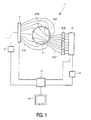
- Fig. 1 shows an embodiment of a device according to the invention, being an optical mammography device 1 in the present case.
- the device according to the invention is described, by way of example, as a mammography device, it can also be used for the examination of other parts of a human or animal body.
- the device described herein is intended for the in vivo localization of inhomogeneities in breast tissue of a part of a breast of a human body.
- a malignant tumor is an example of such an inhomogeneity.
- the device according to the invention is arranged to image such anomalies when they are still very small, so that a carcinoma can be detected at an early stage. However, detection takes place without exposing the patient to the risks of examination by means of ionizing radiation, for example X-rays.
- the device 1 includes a first plurality of N measuring light sources 14-21, a second plurality of M photodetectors 38-45, and a holder 13.
- the numbers N and M are fixed and are valued, for example between 64 and 256. In practice these numbers equal 256 for N as well as M.
- the number of measuring light sources 14-21 and the number of photodetector openings 22-29 are chosen to be equal to eight for the sake of simplicity.
- the device 1 also includes a light source 2, a first optical light conductor 3, a multiple optical switch 4 and the first plurality of second optical conductors 5-12.
- the multiple optical switch 4 connects the light source 1, via the first optical conductor 3 and a second optical conductor, to one of the light transmitting openings 14-21 in the wall of the holder 13, said openings constituting the measuring light sources.
- the light source 2 used is, for example a semiconductor laser with a wavelength of 810 nm.
- the measuring device 1 also includes a third plurality of optical conductors 30-37, a selection unit 39, an analog-to-digital converter 40 and a control device 41.
- the third optical conductors 30-37 are connected, via photodetector openings 22-29 in the wall of the holder 13, to the corresponding number of photodetectors 38-45.
- the exits of the photodetectors 38-45 are connected to the analog-to-digital converter 47 via the selection unit 46.
- the output of the analog-to-digital converter is connected to an input of the control device 48, for example a microcomputer.
- a calibration medium present in the holder 13 of the mammography device 11.
- the calibration medium serves inter alia to couple the light from the measuring light sources into the breast tissue.
- An example of the calibration medium is an Intralipid solution whose attenuation coefficient K l corresponds to a predetermined mean attenuation coefficient of the breast tissue.
- the control unit 48 performs intensity measurements for each measuring light source-photodetector pair (i,j), so that an intensity is measured for the shortest light path between the measuring light source i and the photodetector j of the measuring light source-photodetector pair (i,j).
- the shortest light path is defined as the geometrical distance between the measuring light source i and the photodetector j of the measuring light source-photodetector pair (i.j).
- control unit 48 reconstructs an image of the interior of the part of the breast of the female which is situated within the holder 13.
- a monitor 49 displays the reconstructed image of the interior of the part of the breast.
- Fig. 3 shows a flow chart illustrating the known iterative method.
- a first step represented by a first block 100 in Fig. 3
- the intensities I i,j of each measuring light source/photodetector pair (i,j) of the holder 13 are measured.
- these intensities are stored as a M x N matrix in a memory of the control unit 48.
- an orthogonal system X, Y, Z of voxels which comprises the part of the breast in the holder.
- K x,y,z which coefficients together constitute a three-dimensional matrix.
- a change ⁇ I of the estimated intensity I s (I,J) of the light incident on a photodetector of a measuring light source/photodetector pair I,J of a selected shortest light path is determined from a sum. taken over substantially all voxels present in the part of the breast, of a product of a first function W x (x s ,K) and a weighting function W(x s , ⁇ ,K), where K is equal to the product of the attenuation coefficient K and the distance between the measuring light source and a photodetector opening of the selected shortest light path.
- the estimated intensity associated with the first selected shortest light path is determined and subsequently estimated intensities I s (i,j) are determined for the plurality of shortest light paths i,j.
- the differences ⁇ I(i,j) are determined for each shortest light path of the measured intensity I(i,j) and the estimated intensity I s (i,j). From the differences ⁇ I(i,j) determined an error estimate I f (i,j) is determined in a next step which is represented by a seventh block 106 in Fig. 3.
- a change of the attenuation coefficient K x,y,z of the voxels of the part of the breast is determined in a next step, represented in Fig. 3 by means of an eighth block 107, by way of backprojection of the error estimate.
- the changes of the attenuation coefficient K x,y,z are added to the values of K x,y,z .
- the values K x,y,z will have been determined sufficiently accurately so as to yield an image of the interior of the part of the breast which is suitable for use for diagnostic purposes.
- an image is determined from the three-dimensional matrix of attenuation coefficients K x,y,z .
- I measurement (i,j) represents the measured intensity of the measuring light source/detector pair (i,j) in the breast
- I cal (i,j) represents a previously measured intensity of the measuring light source/detector pair (i,j) in the holder containing the calibration medium only.
- a correction is performed in a version of the method according to the invention. This correction will be described in detail with reference to Fig. 4.
- the correction is determined by a combination of a normalized intensity of the selected shortest light path, the normalized intensities, lengths of the shortest light paths, and a length of the selected shortest light path.
- a value of the combination preferably comprises a linear function of the length of the selected light path and a derivative of the normalized intensity to the length of the light path.
- This linear function can be represented by first reference line along measuring points in a graph, the measuring points corresponding to the plurality of shortest light paths of the measuring light source/detector pairs (i,j), first co-ordinates of said measuring points along a first axis of the graph, being the I' axis, representing the normalized intensities I'(i,j) of the shortest light paths whereas second co-ordinates of said measuring points along a second axis of the graph represent the lengths r(i,j) of the shortest light paths.
- the normalized intensity is given by and represents a logarithm of the ratio of the measured intensity I measurement (i,j) of a selected shortest light path i,j of the measuring light source/detector pair (i,j) in the breast and the calibration medium to a predetermined calibration intensity I cal (i,j) associated with the selected shortest light path in the calibration medium.
- the control unit 48 determines the reference line by means of a linear regression method, for example a least squares method, from the measuring points in the graph.
- the cause of the change of the attenuation coefficient K is a change of the absorption coefficient ⁇ a or of the reduced scatter coefficient ⁇ s '.
- the coupling-in efficiency can be compensated by means of a constant b to be selected. If the absorption coefficient ⁇ a varies as well as the reduced scatter coefficient ⁇ s ', the coupling-in efficiency as well as the change of the reduced scatter coefficient ⁇ s ' can be compensated by means of the constant b.
- the first constant b is determined by the distance between a point of intersection of the reference line l 2 and the I' axis of the graph relative to an origin of the graph.
- the corrected intensity I"(i,j) for a shortest light path r i,j of a measuring light source/detector pair (i,j) is determined by where r(i,j) represents the shortest light path between the measuring light source i and the detector j, a, represents the direction coefficient determined, and b represents the first constant.
- the corrected intensity I"(i,j) then approximates a measured intensity relative to the reference medium whose attenuation coefficient equals the actual mean attenuation coefficient K 2 of the part of the breast. Subsequently, a reconstruction is performed in conformity with the description given with reference to Fig. 3. This yields a three-dimensional matrix of the attenuation coefficients K x,y,z relative to the reference medium.
- the control unit 48 subsequently determines the reconstructed image by selecting attenuation coefficients from the three-dimensional matrix K x,y,z which correspond to voxels in the breast which are situated in one plane.
- the reconstructed image can be corrected for the calibration medium used by adding a second constant to attenuation coefficients of voxels of the turbid medium which correspond to pixels of the reconstructed image, the second constant being equal to the direction coefficient a, determined which corresponds to the difference K 2 -K 1 between the attenuation coefficient of the reference medium and the attenuation coefficient of the calibration medium.
- Fig. 4 shows a graph 40 of reference measuring points 41 which have been obtained by successive measurements, using the device 1, of intensities of the measuring light source/detector pairs (i,j) in the holder 13 containing a reference medium, for example a liquid having an attenuation coefficient K 2 .
- the holder 13 also has a reflective inner wall which has a reflection coefficient of, for example 70%.
- a co-ordinate of a reference measuring point 41 along an I' axis of the graph 40 represents the normalized intensity relative to the calibration medium which is given by the logarithm of the ratio of the measured intensity I ref (i,j) of a selected shortest light path i,j from a reference measuring point associated with the measuring light source/detector pair (i,j) in the reference medium to a previously measured intensity I cal (i,j) associated with the selected shortest light path in the calibration medium.
- a co-ordinate of the reference measuring point 41 along an r axis of the graph 40 represents a length of the selected shortest light path r(i,j) associated with the measuring light source/detector pair (i,j) corresponding to the reference measuring point.
- the graph shows that for a uniform reference medium, having an attenuation coefficient K 2 , the reference measuring points are situated substantially on the reference line l 2 whose direction coefficient a, corresponds to the difference K 2 -K 1 between the attenuation coefficient of the reference medium and that of the calibration medium, respectively.
- the first constant b corresponds to the distance between a point of intersection of the reference line l 2 with the I' axis relative to the origin of the graph 40.
Landscapes
- Health & Medical Sciences (AREA)
- Life Sciences & Earth Sciences (AREA)
- Physics & Mathematics (AREA)
- General Health & Medical Sciences (AREA)
- Pathology (AREA)
- Biomedical Technology (AREA)
- Veterinary Medicine (AREA)
- Heart & Thoracic Surgery (AREA)
- Medical Informatics (AREA)
- Molecular Biology (AREA)
- Surgery (AREA)
- Animal Behavior & Ethology (AREA)
- Biophysics (AREA)
- Public Health (AREA)
- Engineering & Computer Science (AREA)
- Optics & Photonics (AREA)
- Chemical & Material Sciences (AREA)
- Analytical Chemistry (AREA)
- Biochemistry (AREA)
- General Physics & Mathematics (AREA)
- Immunology (AREA)
- Gynecology & Obstetrics (AREA)
- Reproductive Health (AREA)
- Investigating Or Analysing Materials By Optical Means (AREA)
- Measurement Of The Respiration, Hearing Ability, Form, And Blood Characteristics Of Living Organisms (AREA)
Claims (6)
- Procédé de localisation d'un objet dans un milieu trouble, lequel procédé comprend les étapes suivantes :caractérisé en ce que le procédé comprend une étape visant à effectuer une correction des intensités normalisées dans lequel une intensité corrigée d'un trajet de la lumière à sélectionner est déterminée par une combinaison de l'intensité normalisée du chemin lumineux sélectionné, des intensités normalisées, de longueurs des trajets de la lumière et d'une longueur du trajet de la lumière sélectionné.l'immersion du milieu trouble dans un milieu d'étalonnage ;l'irradiation du milieu trouble ;la mesure des intensités d'une partie de la lumière transportée à travers le milieu trouble etle milieu d'étalonnage le long d'une pluralité de trajets de la lumière ;la normalisation des intensités mesurées et la reconstruction d'une image de l'intérieur du milieu trouble à partir des intensités normalisées,
- Procédé suivant la revendication 1, caractérisé en ce qu'une valeur de la combinaison comprend une fonction de la longueur du trajet de la lumière sélectionné et une dérivée de l'intensité normalisée à la longueur du trajet de la lumière.
- Procédé suivant la revendication 1 ou 2, caractérisé en ce que l'intensité normalisée d'un trajet de la lumière à sélectionner est déterminée par un logarithme d'un rapport d'une première intensité d'un trajet de la lumière sélectionné dans le milieu trouble et le milieu d'étalonnage à une deuxième intensité du trajet de la lumière sélectionné dans le milieu d'étalonnage.
- Procédé suivant la revendication 2, caractérisé en ce que la valeur de la combinaison contient une première constante qui est déterminée par la distance entre un point d'intersection de la ligne de référence et le premier axe du graphique par rapport à une origine du graphique, la ligne de référence représentant un logarithme d'un rapport d'une intensité mesurée du milieu d'étalonnage à une intensité mesurée du milieu de référence.
- Procédé suivant la revendication 1, 2 ou 3, caractérisé en ce que l'image reconstruite est corrigée pour le milieu d'étalonnage en ajoutant une deuxième constante à des coefficients d'atténuation de voxels du milieu trouble, lesquels voxels correspondent à des pixels de l'image reconstruite.
- Dispositif pour l'imagerie d'objets dans un milieu trouble, lequel dispositif comprend :caractérisé en ce que le dispositif comprend des moyens de correction pour effectuer une correction des intensités normalisées, une intensité corrigée d'un trajet de la lumière à sélectionner étant déterminée par une combinaison d'une intensité normalisée du trajet de la lumière sélectionné, des intensités normalisées, de longueurs des trajets de la lumière et d'une longueur du trajet de la lumière sélectionné.un support pour un milieu d'étalonnage et pour recevoir le milieu trouble ;une source de lumière pour irradier le milieu trouble et le milieu d'étalonnage ;des moyens pour coupler la lumière à générer par la source de lumière dans le milieu trouble depuis différents angles ;une pluralité de photodétecteurs pour mesurer la lumière transportée à travers le milieu trouble et le milieu d'étalonnage dans différentes directions ;des moyens pour sélectionner un photodétecteur parmi la pluralité de photodétecteurs ;un dispositif de commande pour générer des signaux de commande pour les moyens pour coupler la lumière dans le milieu trouble de différentes directions et pour sélectionner un des photodétecteurs ;des moyens pour normaliser les intensités mesurées, etune unité de commande pour reconstruire une image de l'intérieur du milieu trouble sur la base des intensités mesurées,
Priority Applications (1)
| Application Number | Priority Date | Filing Date | Title |
|---|---|---|---|
| EP98950253A EP0963174B1 (fr) | 1997-11-22 | 1998-11-09 | Procede de localisation d'un objet dans un milieu trouble |
Applications Claiming Priority (4)
| Application Number | Priority Date | Filing Date | Title |
|---|---|---|---|
| EP97203659 | 1997-11-22 | ||
| EP97203659 | 1997-11-22 | ||
| PCT/IB1998/001781 WO1999026526A1 (fr) | 1997-11-22 | 1998-11-09 | Procede de localisation d'un objet dans un milieu trouble |
| EP98950253A EP0963174B1 (fr) | 1997-11-22 | 1998-11-09 | Procede de localisation d'un objet dans un milieu trouble |
Publications (2)
| Publication Number | Publication Date |
|---|---|
| EP0963174A1 EP0963174A1 (fr) | 1999-12-15 |
| EP0963174B1 true EP0963174B1 (fr) | 2004-03-17 |
Family
ID=8228959
Family Applications (1)
| Application Number | Title | Priority Date | Filing Date |
|---|---|---|---|
| EP98950253A Expired - Lifetime EP0963174B1 (fr) | 1997-11-22 | 1998-11-09 | Procede de localisation d'un objet dans un milieu trouble |
Country Status (5)
| Country | Link |
|---|---|
| US (1) | US6230045B1 (fr) |
| EP (1) | EP0963174B1 (fr) |
| JP (1) | JP4043530B2 (fr) |
| DE (1) | DE69822439T2 (fr) |
| WO (1) | WO1999026526A1 (fr) |
Families Citing this family (26)
| Publication number | Priority date | Publication date | Assignee | Title |
|---|---|---|---|---|
| DE69943188D1 (de) * | 1999-06-03 | 2011-03-24 | Hamamatsu Photonics Kk | Optische ct-vorrichtung und verfahren zur wiederherstellung von bildern |
| AU7579300A (en) * | 1999-09-14 | 2001-04-17 | Research Foundation of State University of New York, Technology Transfer Office, The | Method and system for imaging the dynamics of scattering medium |
| WO2001020546A2 (fr) * | 1999-09-14 | 2001-03-22 | The Research Foundation Of State University Of New York | Imagerie de milieux de diffusion au moyen de valeurs de detection relatives |
| ATE422325T1 (de) * | 2000-03-31 | 2009-02-15 | Koninkl Philips Electronics Nv | Verfahren und vorrichtung zur lokalisierung eines abweichenden bereiches in einem trüben medium |
| US6983176B2 (en) * | 2001-04-11 | 2006-01-03 | Rio Grande Medical Technologies, Inc. | Optically similar reference samples and related methods for multivariate calibration models used in optical spectroscopy |
| US6674835B2 (en) | 2001-10-12 | 2004-01-06 | General Electric Co. | Methods and apparatus for estimating a material composition of an imaged object |
| AU2003214166A1 (en) * | 2002-03-13 | 2003-09-29 | Tufts University | Optical imaging and oximetry of tissue |
| US20080218732A1 (en) * | 2005-07-27 | 2008-09-11 | University Of Massachusetts Lowell | Infrared Scanner for Biological Applications |
| US20080106737A1 (en) * | 2005-08-16 | 2008-05-08 | Amnon Weichselbaum | Detecting and counting bacteria suspended in biological fluids |
| WO2007057806A2 (fr) * | 2005-11-18 | 2007-05-24 | Koninklijke Philips Electronics N.V. | Dispositif d’imagerie de l’intérieur d’un milieu trouble |
| JP5261186B2 (ja) * | 2005-11-21 | 2013-08-14 | コーニンクレッカ フィリップス エレクトロニクス エヌ ヴィ | 検出モジュール |
| RU2008125054A (ru) * | 2005-11-23 | 2009-12-27 | Конинклейке Филипс Электроникс Н.В. (Nl) | Способ, система формирования изображения и медицинская система получения изображения содержимого мутной среды, учитывая геометрию мутной среды |
| GB2432660A (en) | 2005-11-29 | 2007-05-30 | Bacterioscan Ltd | System for counting bacteria and determining their susceptibility to antibiotics |
| US20090153850A1 (en) * | 2006-06-14 | 2009-06-18 | Koninklijke Philips Electronics N.V. | Optical fluorescence tomography calibration |
| RU2009117656A (ru) * | 2006-10-09 | 2010-11-20 | Конинклейке Филипс Электроникс Н.В. (Nl) | Построение изображений мутной среды |
| EP2088921A1 (fr) * | 2006-10-30 | 2009-08-19 | Koninklijke Philips Electronics N.V. | Imagerie d'un milieu trouble |
| EP1943941A1 (fr) * | 2006-12-21 | 2008-07-16 | Koninklijke Philips Electronics N.V. | Procédé d'imagerie optique de l'intérieur d'un fluide trouble, procédé de reconstruction d'une image de l'intérieur d'un fluide trouble, dispositif d'imagerie de l'intérieur d'un fluide trouble, dispositif d'acquisition d'images médicales et produits de programme informatique destinés à être utilisés dans lesdits procédés et dispositifs |
| US8355131B2 (en) * | 2007-02-05 | 2013-01-15 | Koninklijke Philips Electronics N.V. | Device and method for acquiring image data from a turbid medium |
| CN101902952B (zh) | 2007-12-17 | 2014-10-29 | 皇家飞利浦电子股份有限公司 | 用于检测混浊介质内部中不均匀性的存在的方法和用于对混浊介质内部成像的设备 |
| JP6479037B2 (ja) | 2013-12-06 | 2019-03-06 | バクテリオスキャン エルティーディー | 試料チャンバを有する光学測定キュベット |
| EP3077796B1 (fr) | 2013-12-06 | 2024-09-18 | IP Specialists Ltd. | Mesures optiques de liquides ayant une surface libre |
| US10233481B2 (en) | 2014-12-05 | 2019-03-19 | Bacterioscan Ltd | Multi-sample laser-scatter measurement instrument with incubation feature and systems for using the same |
| US20160161404A1 (en) | 2014-12-05 | 2016-06-09 | Bacterioscan Ltd | System Using Laser-Scatter Measurement Instrument For Organism Identification And Related Network |
| US10065184B2 (en) | 2014-12-30 | 2018-09-04 | Bacterioscan Ltd. | Pipette having integrated filtration assembly |
| JP2018503842A (ja) | 2015-01-26 | 2018-02-08 | バクテリオスキャン エルティーディー | 回転木馬式流体サンプル配置を呈するレーザ散乱計測器具 |
| US11099121B2 (en) | 2019-02-05 | 2021-08-24 | BacterioScan Inc. | Cuvette device for determining antibacterial susceptibility |
Family Cites Families (6)
| Publication number | Priority date | Publication date | Assignee | Title |
|---|---|---|---|---|
| US5596987A (en) * | 1988-11-02 | 1997-01-28 | Noninvasive Technology, Inc. | Optical coupler for in vivo examination of biological tissue |
| US5555885A (en) * | 1988-12-21 | 1996-09-17 | Non-Invasive Technology, Inc. | Examination of breast tissue using time-resolved spectroscopy |
| EP0836409B1 (fr) * | 1996-04-02 | 2004-03-17 | Koninklijke Philips Electronics N.V. | Localisation d'un objet dans un milieu trouble par l'intermediaire d'un rayonnement de differentes longueurs d'onde |
| JP4138009B2 (ja) * | 1996-08-14 | 2008-08-20 | コーニンクレッカ フィリップス エレクトロニクス エヌ ヴィ | 境界効果を低下するために液体を用いる混濁状媒体の画像形成 |
| EP0877927A1 (fr) * | 1996-08-14 | 1998-11-18 | Koninklijke Philips Electronics N.V. | Dispositif et procede de formation d'image d'un objet opaque |
| JP3844815B2 (ja) * | 1996-08-30 | 2006-11-15 | 浜松ホトニクス株式会社 | 散乱体の吸収情報計測方法及び装置 |
-
1998
- 1998-11-09 DE DE69822439T patent/DE69822439T2/de not_active Expired - Lifetime
- 1998-11-09 WO PCT/IB1998/001781 patent/WO1999026526A1/fr not_active Ceased
- 1998-11-09 JP JP52799599A patent/JP4043530B2/ja not_active Expired - Fee Related
- 1998-11-09 EP EP98950253A patent/EP0963174B1/fr not_active Expired - Lifetime
- 1998-11-20 US US09/197,310 patent/US6230045B1/en not_active Expired - Lifetime
Also Published As
| Publication number | Publication date |
|---|---|
| EP0963174A1 (fr) | 1999-12-15 |
| JP4043530B2 (ja) | 2008-02-06 |
| DE69822439D1 (de) | 2004-04-22 |
| JP2001509902A (ja) | 2001-07-24 |
| DE69822439T2 (de) | 2005-01-20 |
| US6230045B1 (en) | 2001-05-08 |
| WO1999026526A1 (fr) | 1999-06-03 |
Similar Documents
| Publication | Publication Date | Title |
|---|---|---|
| EP0963174B1 (fr) | Procede de localisation d'un objet dans un milieu trouble | |
| US6064073A (en) | Method of localizing an object in a turbid medium | |
| US8239006B2 (en) | Method and apparatus for medical imaging using near-infrared optical tomography and fluorescence tomography combined with ultrasound | |
| US8326406B2 (en) | Method and system for free space optical tomography of diffuse media | |
| CN101980656B (zh) | 用于重构混浊介质内部的荧光图像的方法以及用于对混浊介质内部成像的设备 | |
| Brooksby et al. | Magnetic resonance-guided near-infrared tomography of the breast | |
| JP4138009B2 (ja) | 境界効果を低下するために液体を用いる混濁状媒体の画像形成 | |
| US9341569B2 (en) | Method for detecting the presence of inhomogeneities in an interior of a turbid medium and device for imaging the interior of turbid media | |
| JP5543212B2 (ja) | 前立腺癌のイメージング用システム、前立腺癌をイメージングするシステムの作動方法及びコンピュータ読取可能媒体 | |
| US20130155407A1 (en) | Method for reconstructing the optical properties of a medium using a combination of a plurality of mellin-laplace transforms of a magnitude comprising a time distribution of a received signal, and associated reconstruction system | |
| US5903357A (en) | Method and apparatus for imaging an interior of a turbid medium | |
| US6327489B1 (en) | Method of localizing an object in a turbid medium | |
| WO1998007021A1 (fr) | Dispositif et procede de formation d'image d'un objet opaque | |
| JP2001510361A (ja) | 混濁媒体の内部を画像化する方法及び装置 | |
| Pogue et al. | Imaging hemoglobin concentration and oxygen saturation in the female breast with near-infrared diffusion tomography | |
| WO2009060383A2 (fr) | Procédé d'étalonnage d'un dispositif d'imagerie de l'intérieur d'un milieu trouble et procédé de correction des intensités mesurées dans ce dispositif | |
| Hwang | Improved fluorescence-enhanced optical imaging and tomography by enhanced excitation light rejection |
Legal Events
| Date | Code | Title | Description |
|---|---|---|---|
| PUAI | Public reference made under article 153(3) epc to a published international application that has entered the european phase |
Free format text: ORIGINAL CODE: 0009012 |
|
| AK | Designated contracting states |
Kind code of ref document: A1 Designated state(s): DE FR GB NL |
|
| 17P | Request for examination filed |
Effective date: 19991203 |
|
| GRAP | Despatch of communication of intention to grant a patent |
Free format text: ORIGINAL CODE: EPIDOSNIGR1 |
|
| GRAS | Grant fee paid |
Free format text: ORIGINAL CODE: EPIDOSNIGR3 |
|
| GRAA | (expected) grant |
Free format text: ORIGINAL CODE: 0009210 |
|
| AK | Designated contracting states |
Kind code of ref document: B1 Designated state(s): DE FR GB NL |
|
| PG25 | Lapsed in a contracting state [announced via postgrant information from national office to epo] |
Ref country code: NL Free format text: LAPSE BECAUSE OF FAILURE TO SUBMIT A TRANSLATION OF THE DESCRIPTION OR TO PAY THE FEE WITHIN THE PRESCRIBED TIME-LIMIT Effective date: 20040317 |
|
| REG | Reference to a national code |
Ref country code: GB Ref legal event code: FG4D |
|
| REF | Corresponds to: |
Ref document number: 69822439 Country of ref document: DE Date of ref document: 20040422 Kind code of ref document: P |
|
| NLV1 | Nl: lapsed or annulled due to failure to fulfill the requirements of art. 29p and 29m of the patents act | ||
| ET | Fr: translation filed | ||
| PG25 | Lapsed in a contracting state [announced via postgrant information from national office to epo] |
Ref country code: GB Free format text: LAPSE BECAUSE OF NON-PAYMENT OF DUE FEES Effective date: 20041109 |
|
| REG | Reference to a national code |
Ref country code: FR Ref legal event code: D6 |
|
| PLBE | No opposition filed within time limit |
Free format text: ORIGINAL CODE: 0009261 |
|
| STAA | Information on the status of an ep patent application or granted ep patent |
Free format text: STATUS: NO OPPOSITION FILED WITHIN TIME LIMIT |
|
| 26N | No opposition filed |
Effective date: 20041220 |
|
| GBPC | Gb: european patent ceased through non-payment of renewal fee |
Effective date: 20041109 |
|
| REG | Reference to a national code |
Ref country code: DE Ref legal event code: R082 Ref document number: 69822439 Country of ref document: DE Representative=s name: MEYER, MICHAEL, DIPL.-ING., DE |
|
| REG | Reference to a national code |
Ref country code: DE Ref legal event code: R082 Ref document number: 69822439 Country of ref document: DE Representative=s name: MEYER, MICHAEL, DIPL.-ING., DE Effective date: 20140331 Ref country code: DE Ref legal event code: R081 Ref document number: 69822439 Country of ref document: DE Owner name: KONINKLIJKE PHILIPS N.V., NL Free format text: FORMER OWNER: KONINKLIJKE PHILIPS ELECTRONICS N.V., EINDHOVEN, NL Effective date: 20140331 |
|
| REG | Reference to a national code |
Ref country code: FR Ref legal event code: CD Owner name: KONINKLIJKE PHILIPS N.V., NL Effective date: 20141126 Ref country code: FR Ref legal event code: CA Effective date: 20141126 |
|
| REG | Reference to a national code |
Ref country code: FR Ref legal event code: PLFP Year of fee payment: 18 |
|
| REG | Reference to a national code |
Ref country code: FR Ref legal event code: PLFP Year of fee payment: 19 |
|
| PGFP | Annual fee paid to national office [announced via postgrant information from national office to epo] |
Ref country code: FR Payment date: 20161129 Year of fee payment: 19 |
|
| PGFP | Annual fee paid to national office [announced via postgrant information from national office to epo] |
Ref country code: DE Payment date: 20170131 Year of fee payment: 19 |
|
| REG | Reference to a national code |
Ref country code: DE Ref legal event code: R119 Ref document number: 69822439 Country of ref document: DE |
|
| REG | Reference to a national code |
Ref country code: FR Ref legal event code: ST Effective date: 20180731 |
|
| PG25 | Lapsed in a contracting state [announced via postgrant information from national office to epo] |
Ref country code: DE Free format text: LAPSE BECAUSE OF NON-PAYMENT OF DUE FEES Effective date: 20180602 Ref country code: FR Free format text: LAPSE BECAUSE OF NON-PAYMENT OF DUE FEES Effective date: 20171130 |