EP0963499B1 - Systeme d'entrainement pour porte a tambour - Google Patents
Systeme d'entrainement pour porte a tambour Download PDFInfo
- Publication number
- EP0963499B1 EP0963499B1 EP98966340A EP98966340A EP0963499B1 EP 0963499 B1 EP0963499 B1 EP 0963499B1 EP 98966340 A EP98966340 A EP 98966340A EP 98966340 A EP98966340 A EP 98966340A EP 0963499 B1 EP0963499 B1 EP 0963499B1
- Authority
- EP
- European Patent Office
- Prior art keywords
- swing door
- door operator
- door
- operator according
- drive
- Prior art date
- Legal status (The legal status is an assumption and is not a legal conclusion. Google has not performed a legal analysis and makes no representation as to the accuracy of the status listed.)
- Expired - Lifetime
Links
- 230000005540 biological transmission Effects 0.000 claims abstract description 10
- 238000006073 displacement reaction Methods 0.000 claims description 5
- 230000003134 recirculating effect Effects 0.000 claims 1
- 238000000034 method Methods 0.000 description 3
- 238000013459 approach Methods 0.000 description 2
- 238000010276 construction Methods 0.000 description 2
- 238000013461 design Methods 0.000 description 2
- 238000009434 installation Methods 0.000 description 2
- 238000012545 processing Methods 0.000 description 2
- TVEXGJYMHHTVKP-UHFFFAOYSA-N 6-oxabicyclo[3.2.1]oct-3-en-7-one Chemical compound C1C2C(=O)OC1C=CC2 TVEXGJYMHHTVKP-UHFFFAOYSA-N 0.000 description 1
- 230000006399 behavior Effects 0.000 description 1
- 230000008878 coupling Effects 0.000 description 1
- 238000010168 coupling process Methods 0.000 description 1
- 238000005859 coupling reaction Methods 0.000 description 1
- 238000013016 damping Methods 0.000 description 1
- 238000011161 development Methods 0.000 description 1
- 238000005265 energy consumption Methods 0.000 description 1
- 238000004146 energy storage Methods 0.000 description 1
- 238000004519 manufacturing process Methods 0.000 description 1
- 230000000149 penetrating effect Effects 0.000 description 1
- 230000001105 regulatory effect Effects 0.000 description 1
- 238000009420 retrofitting Methods 0.000 description 1
- 230000008054 signal transmission Effects 0.000 description 1
Images




Classifications
-
- E—FIXED CONSTRUCTIONS
- E05—LOCKS; KEYS; WINDOW OR DOOR FITTINGS; SAFES
- E05F—DEVICES FOR MOVING WINGS INTO OPEN OR CLOSED POSITION; CHECKS FOR WINGS; WING FITTINGS NOT OTHERWISE PROVIDED FOR, CONCERNED WITH THE FUNCTIONING OF THE WING
- E05F15/00—Power-operated mechanisms for wings
- E05F15/60—Power-operated mechanisms for wings using electrical actuators
- E05F15/603—Power-operated mechanisms for wings using electrical actuators using rotary electromotors
- E05F15/611—Power-operated mechanisms for wings using electrical actuators using rotary electromotors for swinging wings
-
- E—FIXED CONSTRUCTIONS
- E05—LOCKS; KEYS; WINDOW OR DOOR FITTINGS; SAFES
- E05F—DEVICES FOR MOVING WINGS INTO OPEN OR CLOSED POSITION; CHECKS FOR WINGS; WING FITTINGS NOT OTHERWISE PROVIDED FOR, CONCERNED WITH THE FUNCTIONING OF THE WING
- E05F15/00—Power-operated mechanisms for wings
- E05F15/60—Power-operated mechanisms for wings using electrical actuators
- E05F15/603—Power-operated mechanisms for wings using electrical actuators using rotary electromotors
- E05F15/611—Power-operated mechanisms for wings using electrical actuators using rotary electromotors for swinging wings
- E05F15/616—Power-operated mechanisms for wings using electrical actuators using rotary electromotors for swinging wings operated by push-pull mechanisms
- E05F15/619—Power-operated mechanisms for wings using electrical actuators using rotary electromotors for swinging wings operated by push-pull mechanisms using flexible or rigid rack-and-pinion arrangements
-
- E—FIXED CONSTRUCTIONS
- E05—LOCKS; KEYS; WINDOW OR DOOR FITTINGS; SAFES
- E05F—DEVICES FOR MOVING WINGS INTO OPEN OR CLOSED POSITION; CHECKS FOR WINGS; WING FITTINGS NOT OTHERWISE PROVIDED FOR, CONCERNED WITH THE FUNCTIONING OF THE WING
- E05F15/00—Power-operated mechanisms for wings
- E05F15/60—Power-operated mechanisms for wings using electrical actuators
- E05F15/603—Power-operated mechanisms for wings using electrical actuators using rotary electromotors
- E05F15/611—Power-operated mechanisms for wings using electrical actuators using rotary electromotors for swinging wings
- E05F15/616—Power-operated mechanisms for wings using electrical actuators using rotary electromotors for swinging wings operated by push-pull mechanisms
- E05F15/622—Power-operated mechanisms for wings using electrical actuators using rotary electromotors for swinging wings operated by push-pull mechanisms using screw-and-nut mechanisms
-
- E—FIXED CONSTRUCTIONS
- E05—LOCKS; KEYS; WINDOW OR DOOR FITTINGS; SAFES
- E05F—DEVICES FOR MOVING WINGS INTO OPEN OR CLOSED POSITION; CHECKS FOR WINGS; WING FITTINGS NOT OTHERWISE PROVIDED FOR, CONCERNED WITH THE FUNCTIONING OF THE WING
- E05F15/00—Power-operated mechanisms for wings
- E05F15/60—Power-operated mechanisms for wings using electrical actuators
- E05F15/603—Power-operated mechanisms for wings using electrical actuators using rotary electromotors
- E05F15/611—Power-operated mechanisms for wings using electrical actuators using rotary electromotors for swinging wings
- E05F15/63—Power-operated mechanisms for wings using electrical actuators using rotary electromotors for swinging wings operated by swinging arms
-
- E—FIXED CONSTRUCTIONS
- E05—LOCKS; KEYS; WINDOW OR DOOR FITTINGS; SAFES
- E05F—DEVICES FOR MOVING WINGS INTO OPEN OR CLOSED POSITION; CHECKS FOR WINGS; WING FITTINGS NOT OTHERWISE PROVIDED FOR, CONCERNED WITH THE FUNCTIONING OF THE WING
- E05F3/00—Closers or openers with braking devices, e.g. checks; Construction of pneumatic or liquid braking devices
- E05F3/04—Closers or openers with braking devices, e.g. checks; Construction of pneumatic or liquid braking devices with liquid piston brakes
- E05F3/10—Closers or openers with braking devices, e.g. checks; Construction of pneumatic or liquid braking devices with liquid piston brakes with a spring, other than a torsion spring, and a piston, the axes of which are the same or lie in the same direction
- E05F3/102—Closers or openers with braking devices, e.g. checks; Construction of pneumatic or liquid braking devices with liquid piston brakes with a spring, other than a torsion spring, and a piston, the axes of which are the same or lie in the same direction with rack-and-pinion transmission between driving shaft and piston within the closer housing
-
- E—FIXED CONSTRUCTIONS
- E05—LOCKS; KEYS; WINDOW OR DOOR FITTINGS; SAFES
- E05Y—INDEXING SCHEME ASSOCIATED WITH SUBCLASSES E05D AND E05F, RELATING TO CONSTRUCTION ELEMENTS, ELECTRIC CONTROL, POWER SUPPLY, POWER SIGNAL OR TRANSMISSION, USER INTERFACES, MOUNTING OR COUPLING, DETAILS, ACCESSORIES, AUXILIARY OPERATIONS NOT OTHERWISE PROVIDED FOR, APPLICATION THEREOF
- E05Y2201/00—Constructional elements; Accessories therefor
- E05Y2201/40—Motors; Magnets; Springs; Weights; Accessories therefor
- E05Y2201/43—Motors
- E05Y2201/434—Electromotors; Details thereof
-
- E—FIXED CONSTRUCTIONS
- E05—LOCKS; KEYS; WINDOW OR DOOR FITTINGS; SAFES
- E05Y—INDEXING SCHEME ASSOCIATED WITH SUBCLASSES E05D AND E05F, RELATING TO CONSTRUCTION ELEMENTS, ELECTRIC CONTROL, POWER SUPPLY, POWER SIGNAL OR TRANSMISSION, USER INTERFACES, MOUNTING OR COUPLING, DETAILS, ACCESSORIES, AUXILIARY OPERATIONS NOT OTHERWISE PROVIDED FOR, APPLICATION THEREOF
- E05Y2201/00—Constructional elements; Accessories therefor
- E05Y2201/60—Suspension or transmission members; Accessories therefor
- E05Y2201/622—Suspension or transmission members elements
- E05Y2201/71—Toothed gearing
- E05Y2201/722—Racks
-
- E—FIXED CONSTRUCTIONS
- E05—LOCKS; KEYS; WINDOW OR DOOR FITTINGS; SAFES
- E05Y—INDEXING SCHEME ASSOCIATED WITH SUBCLASSES E05D AND E05F, RELATING TO CONSTRUCTION ELEMENTS, ELECTRIC CONTROL, POWER SUPPLY, POWER SIGNAL OR TRANSMISSION, USER INTERFACES, MOUNTING OR COUPLING, DETAILS, ACCESSORIES, AUXILIARY OPERATIONS NOT OTHERWISE PROVIDED FOR, APPLICATION THEREOF
- E05Y2400/00—Electronic control; Electrical power; Power supply; Power or signal transmission; User interfaces
- E05Y2400/10—Electronic control
- E05Y2400/30—Electronic control of motors
- E05Y2400/3013—Electronic control of motors during manual wing operation
-
- E—FIXED CONSTRUCTIONS
- E05—LOCKS; KEYS; WINDOW OR DOOR FITTINGS; SAFES
- E05Y—INDEXING SCHEME ASSOCIATED WITH SUBCLASSES E05D AND E05F, RELATING TO CONSTRUCTION ELEMENTS, ELECTRIC CONTROL, POWER SUPPLY, POWER SIGNAL OR TRANSMISSION, USER INTERFACES, MOUNTING OR COUPLING, DETAILS, ACCESSORIES, AUXILIARY OPERATIONS NOT OTHERWISE PROVIDED FOR, APPLICATION THEREOF
- E05Y2400/00—Electronic control; Electrical power; Power supply; Power or signal transmission; User interfaces
- E05Y2400/61—Power supply
- E05Y2400/612—Batteries
-
- E—FIXED CONSTRUCTIONS
- E05—LOCKS; KEYS; WINDOW OR DOOR FITTINGS; SAFES
- E05Y—INDEXING SCHEME ASSOCIATED WITH SUBCLASSES E05D AND E05F, RELATING TO CONSTRUCTION ELEMENTS, ELECTRIC CONTROL, POWER SUPPLY, POWER SIGNAL OR TRANSMISSION, USER INTERFACES, MOUNTING OR COUPLING, DETAILS, ACCESSORIES, AUXILIARY OPERATIONS NOT OTHERWISE PROVIDED FOR, APPLICATION THEREOF
- E05Y2600/00—Mounting or coupling arrangements for elements provided for in this subclass
- E05Y2600/40—Mounting location; Visibility of the elements
- E05Y2600/41—Concealed
-
- E—FIXED CONSTRUCTIONS
- E05—LOCKS; KEYS; WINDOW OR DOOR FITTINGS; SAFES
- E05Y—INDEXING SCHEME ASSOCIATED WITH SUBCLASSES E05D AND E05F, RELATING TO CONSTRUCTION ELEMENTS, ELECTRIC CONTROL, POWER SUPPLY, POWER SIGNAL OR TRANSMISSION, USER INTERFACES, MOUNTING OR COUPLING, DETAILS, ACCESSORIES, AUXILIARY OPERATIONS NOT OTHERWISE PROVIDED FOR, APPLICATION THEREOF
- E05Y2600/00—Mounting or coupling arrangements for elements provided for in this subclass
- E05Y2600/40—Mounting location; Visibility of the elements
- E05Y2600/46—Mounting location; Visibility of the elements in or on the wing
-
- E—FIXED CONSTRUCTIONS
- E05—LOCKS; KEYS; WINDOW OR DOOR FITTINGS; SAFES
- E05Y—INDEXING SCHEME ASSOCIATED WITH SUBCLASSES E05D AND E05F, RELATING TO CONSTRUCTION ELEMENTS, ELECTRIC CONTROL, POWER SUPPLY, POWER SIGNAL OR TRANSMISSION, USER INTERFACES, MOUNTING OR COUPLING, DETAILS, ACCESSORIES, AUXILIARY OPERATIONS NOT OTHERWISE PROVIDED FOR, APPLICATION THEREOF
- E05Y2800/00—Details, accessories and auxiliary operations not otherwise provided for
- E05Y2800/25—Emergency conditions
- E05Y2800/252—Emergency conditions the elements functioning only in case of emergency
-
- E—FIXED CONSTRUCTIONS
- E05—LOCKS; KEYS; WINDOW OR DOOR FITTINGS; SAFES
- E05Y—INDEXING SCHEME ASSOCIATED WITH SUBCLASSES E05D AND E05F, RELATING TO CONSTRUCTION ELEMENTS, ELECTRIC CONTROL, POWER SUPPLY, POWER SIGNAL OR TRANSMISSION, USER INTERFACES, MOUNTING OR COUPLING, DETAILS, ACCESSORIES, AUXILIARY OPERATIONS NOT OTHERWISE PROVIDED FOR, APPLICATION THEREOF
- E05Y2900/00—Application of doors, windows, wings or fittings thereof
- E05Y2900/10—Application of doors, windows, wings or fittings thereof for buildings or parts thereof
- E05Y2900/13—Type of wing
- E05Y2900/132—Doors
Definitions
- the invention relates to a concealed swing door drive with an electronic Control or regulation, the at least one memory and one Microprocessor contains, for a door with at least one wing, the Door leaf of an electromechanical acting in the opening and closing direction Drive unit is driven, the drive unit essentially from a drive motor with an adjoining one Power transmission unit exists, and the power transmission unit one Has drive shaft connected to one end of an operating lever and the entire swing door drive within one door leaf or can be installed invisibly within a frame.
- Automatic door drives have the purpose of inspecting doors facilitate. Their importance grows not only in public and commercial used real estate, e.g. Administrative institutions, hospitals, Retirement homes, but there are increasingly automatic door drives used especially for apartments suitable for the disabled.
- the door drives are always on the door leaf or above the Door frame (frame) installed.
- DE 42 31 984 A discloses an electromechanical swing door drive, equipped with a data processing unit for optimal operation is.
- the data processing unit is a motor control unit connected, which forwards its output signal to a geared motor.
- the opening process of such a revolving door is monitored by a sensor signal initiated and executed automatically by the drive. simultaneously when opening an energy storage with the necessary Energy supplied to subsequently such a door without electrical Bring energy back to the secure closed position. This is also in the event of a failure of the engine control unit in the de-energized state, a safe one Guaranteed closing of the connected wing.
- DE 296 04 692 U1 is a device for actuating a window sash refer to.
- chain links are created within the wing embedded by a worm geared one Motors are moved.
- the clutch consists of one on the drive axle non-positively and positively attached locking bolts and at least one locking mark contained therein. Within the locking mark is a bolt that is spring-loaded and with a infinitely adjustable power adjustment is provided. By adjusting the force it is possible to continuously adjust the release force.
- Another version can also be that the upper cross member of the rotating wing with two interlocking hook-shaped holding arms is provided.
- the support arms interlock so that even in one direction, namely in the direction of the escape and rescue route, the rotary wing can be uncoupled from the drive is.
- the object of the invention is an automatic drive for to create a revolving door that is very small and its appearance does not affect the architectural impression of a door,
- a swing door drive should be inexpensive to manufacture be and work almost maintenance-free.
- a Spindle Inside the spindle nut is a Spindle, preferably a ball screw at one end, wherein the other end of the spindle is held in a bearing.
- the spindle is driven by a driver axis that emerges from a gearbox driven.
- the gearbox is connected to a drive motor.
- a displacement sensor on the revolving door drive which is preferably an incremental encoder or can be a potentiometer.
- The is controlled Motor through a controller that contains a microprocessor and memory and implemented as a PLC control (self-programming control) can be controlled.
- the controller is controlled by a sensor signal, which, for example, by a transmitter located within the Sensor is located to a receiver that is within the controller and so that it is embedded within the door leaf. So that Swing door drive can work independently, it is preferably with a corresponding Battery pack or an accumulator equipped. In use of the idea according to the invention, however, it is also possible that the power supply to the control system via appropriate supply lines, which are realized by cables with the necessary energy becomes. In such a case, the connection between Sensor and control can be realized by cable, the sensor can also be a switch.
- control If the control is activated by the sensor signal, it turns the spindle and thereby causes the rack to move, which in turn is a forced movement due to the coupling via the Lever which is displaceably mounted on the other side on the slide, causes. Due to the preset opening width of the door remains in the Angle of the drive are at the same time the door leaf is in this position held. This can be achieved, for example, in that a self-locking gear is used. However, it is also possible, with appropriate regulation of the control, however a higher energy consumption after the drive motor the door holds in the open position and after an adjustable Automatically brings time back to the closed position. Keeping the Door through the motor generates corresponding power losses that lead to a Can cause the engine to heat up. It is also possible to set a holding torque through an electromagnetic clutch or through to generate a brake.
- the main task of the controller is the motor current or the motor voltage depending on the door position and the Request signal, e.g. of a sensor to regulate.
- the engine can can be short-circuited with the door closed, thus providing an additional one Closing moment available. If an opening signal is given, then the motor current is regulated along the motor torque characteristic. After reaching the specified maximum speed, the engine speed based on the data from the displacement sensor in connection with a Sequence program, which was opened by opening the door the first time tutorial was determined, held constant up to a braking point. When the door is braked, the motor current is reduced Limit value than when accelerating. Running to close the door this process in reverse. When exceeding the permissible Motor current, e.g. due to an obstacle, the controller switch off the drive accordingly or the door in reverse position drive. The end positions of the door and the braking points of the Controls are also determined in the learning phase.
- both the drive unit in particular consisting of rack, spindle with nut, gear, motor and displacement sensors as well as the control and the power supply.
- the drive unit in particular consisting of rack, spindle with nut, gear, motor and displacement sensors as well as the control and the power supply.
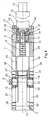
- FIG. 1 shows a revolving door drive which is located in a door 53 within a Recess 55 is installed. It is in the exemplary embodiment a wooden door. But it can also be the swing door drive due to its conceptually small dimensions within a frame of a profile door to be built in. It is also possible to use the swing door drive not, as shown in FIG. 1, to be installed inside a door 53, but in a frame or door frame above it, which are not shown in the exemplary embodiment. Furthermore, in the Embodiment does not show the striking of the door 53 on tapes, neither is the actuating arm, the one with the one above Slide the slide rail and its slide back and forth in it can and the connection between the swing door drive (door) and the fixed Part, namely the frame.
- the recess 55 is like this sized that a cover 49 is recessed within a recess is, with both the revolving door drive with the cover 49 its drive unit as well as a power supply 52 for control 51 and a possibly existing signal transmission in the form a receiver 54 is located. All components are in a row.
- the entire swing door drive is by means of the cover 49 and this penetrating screw connections 50 with the door 53 non-positively and positively connected.
- the swing door drive is is an electromechanical swing door drive that is powered by a drive motor 10, which is connected to a gear 9, the connected Door 53 is intended to move.
- the housing is there consequently from the construction elements that make up the drive unit is preferably produced.
- These are particular an upper cover plate 1 and a lower cover plate 24, the cover plate 1 in Figure 2 above and the cover plate 24 below. apart the cover plates 1 and 24 at one end by an end piece 4 and elsewhere by a bearing bracket 2.
- the end piece 4 is through Screw connections 20 between the cover plates 1 and 24 non-positively and positively clamped.
- the bearing bracket 2 is on a bearing flange 3 on which the gear 9 is flanged to the drive motor 10 by screw connections 19, which both the bearing flange 3 and the bearing bracket 2 reach through, and in the cover plates 1, 24 via appropriate threads are screwed together.
- the device for translational movement the swing door drive consists essentially of one Rack 5, a spindle nut 7 and one within the spindle nut engaging spindle 8.
- the rack 5 is arranged against rotation in such a way that within the cover plates 1 recesses 25 and 26 and in the Cover plate 24 recesses 34 and 35 are located in each one the rack 5 molded guide pin 27, 28 and 32, 33 in Longitudinal direction of the swing door drive is mounted (see in particular figures 3 and 4).
- a drive axle is in operative connection with the rack 5 22 is present, which protrudes at one end from the cover plate 1 and has an actuating cam 6, on which the aforementioned Connection, not shown, via the actuating arm for the Slide rail is articulated.
- the rack 5 thus slides in the region of the guide pins 27, 28 and 32, 33 of existing surfaces 40, 41, 42, 43 between the cover plates 1 and 24.
- the rack 5 is shown in particular in FIGS. 6, 7 and 8, which show the individual views of the rack 5, shown.
- the rack 5 is tapered in relation to the horizontal axis, namely through recesses 37 and 38.
- a spindle nut receptacle 44 On one of the end walls of the Rack 5 is a spindle nut receptacle 44, which is designed in this way is that the spindle nut 7 is non-positively and positively connected here can be. This can be a thread 36, for example. It is however, it is also possible to remove the spindle nut 7 and the rack 5 to make one piece.
- FIG. 4 shows a more detailed structure of the swing door drive, in which the swing door drive is shown in side view and in addition, a sectional view was selected in some areas is.
- the connection between the spindle nut 7 and the rack 5 visible, in which case a connection via the thread 36 on a projection formed on the spindle nut 7 29 was chosen.
- the spindle 8 engages within the spindle nut 7 one, which can preferably be a ball screw to reduce the friction losses to keep it as low as possible.
- the end of the spindle 8, which does not pass through the spindle nut 7 is in the bearing bracket 2 held with a bearing boss 13 within a spindle bearing 17.
- connection of the gear is located within the bearing flange 3 9 via screw connections 21.
- the gear 9 has a driver axis 15 on that in the embodiment within the bearing approach 13, here e.g. over a square, is inserted and thus when the driving axis 15 rotates, the spindle 8 is also rotated becomes.
- any other non-positive and form-fitting one Detachable connection can be chosen, especially in the form a tongue and groove connection.
- the drive axle 22 as can also be seen in FIG. 4, guided within the cover plates 1 and 24 via bearing 16. Doing so the bearing 16 within blind bores 30. With the actuating cam 6, the drive shaft 22 protrudes from the cover plate 1.
- Swing door drive can also work independently, as in the embodiment reproduced in Figure 1, a power supply 52 used which keeps the door in operation in the form of a battery.
- a power supply 52 used which keeps the door in operation in the form of a battery.
- such a door should be placed at busy entrances would be, the performance of a battery would not be sufficient, and in this If it is possible, it is also possible to use appropriate cable feeds the power supply with the necessary drive energy for the control 51 and thus to supply the drive motor 10.
- the senor can also be wired with what means that the receiver 54 can be omitted.
- the damping of the connected door 53 is accomplished electrically. Because both the electromechanical drive and the power supply and control installed inside the door 53 or the frame no wall or floor openings are required for installation. Furthermore, the swing door drive is particularly suitable for retrofitting, since it can also be retrofitted in doors, including profile frame doors can be, this especially for the elderly, as well as through a sudden restriction of their mobility disabled people is an interesting alternative to new doors.
Landscapes
- Power-Operated Mechanisms For Wings (AREA)
- Lock And Its Accessories (AREA)
- Light Receiving Elements (AREA)
- Solid State Image Pick-Up Elements (AREA)
- Electric Ovens (AREA)
Claims (16)
- Système d'entraínement pour porte tournante comprenant une commande électronique, qui inclut au moins une mémoire et un microprocesseur, pour une porte avec au moins un vantail, le vantail de laquelle est entraíné par une unité d'entraínement électromécanique fonctionnant dans le sens de l'ouverture et dans le sens de la fermeture, qui consiste essentiellement d'un moteur d'entraínement (10) avec un engrenage (9) et y raccordée d'une unité de transmission de force pour la porte connectée, l'unité de transmission de force étant composée d'une broche (8) avec un écrou de broche (7), qui la recouvre en partie et qui est reliée par la force et par la forme avec une crémaillère (5), et d'un axe d'entraínement (22) s'engrenant avec sa denture (56) dans une denture (23) de la crémaillère (5), et l'axe d'entraínement (22) étant connectée avec une extrémité d'un levier d'actionnement, et le système d'entraínement pour porte tournante pouvant être installé de façon invisible dans un vantail de porte, respectivement dans un encadrement de porte.
- Système d'entraínement pour porte tournante selon la revendication 1, caractérisé en ce que la crémaillère (5) est sécurisée résistante à la rotation.
- Système d'entraínement pour porte tournante selon la revendication 2, caractérisé en ce que la sécurité anti-rotation est achevée par l'intermédiaire de pignons de guidage (27, 28, 32, 33) présents sur la crémaillère (5) et leur engagement dans des réceptions (25, 26, 34, 35) qui se trouvent sur les plaques (1, 24).
- Système d'entraínement pour porte tournante selon l'une ou plusieurs des revendications précédentes, caractérisé en ce que les plaques de couverture (1, 24) sont espacée à une extrémité par un embout (4) et à l'autre extrémité par un support de palier (2), et entre les plaques de couverture (1, 24) se trouvent la crémaillère (5), l'écrou de broche (7) avec une extrémité de la broche (8) y logée intérieurement, et la broche (8) est logée à l'autre extrémité dans le support de palier (2).
- Système d'entraínement pour porte tournante selon l'une ou plusieurs des revendications précédentes, caractérisé en ce que une bride de palier (3) est raccordée par la force et par la forme au support de palier (2), sur laquelle est fixé le moteur d'entraínement (10) avec un engrenage (9) et un capteur de déplacement (11).
- Système d'entraínement pour porte tournante selon les revendications 1 et 4, caractérisé en ce que l'engrenage (9) n'est pas auto-verrouillant.
- Système d'entraínement pour porte tournante selon la revendication 5, caractérisé en ce que le capteur de déplacement (11) est un encodeur incrémentiel.
- Système d'entraínement pour porte tournante selon la revendication 4, caractérisé en ce que la broche (8) est une vis à billes.
- Système d'entraínement pour porte tournante selon les revendications 1, 4, 5 et 8, caractérisé en ce que la broche (8) présente une réception pour un axe d'entraíneur (15) de l'engrenage (9).
- Système d'entraínement pour porte tournante selon les revendications précédentes, caractérisé en ce que le système d'entraínement pour porte tournante présente une largeur maximale de l'ordre de 35 mm.
- Système d'entraínement pour porte tournante selon la revendication 1, caractérisé en ce que la deuxième extrémité du levier d'actionnement est raccordée à une pièce coulissante qui est mobile dans une glissière le long de la glissière, montée à l'intérieur de la porte respectivement à l'intérieur de l'encadrement de la porte.
- Système d'entraínement pour porte tournante selon la revendication 1, caractérisé en ce que l'écrou de broche (7) et la crémaillère (5) sont d'un unique tenant.
- Système d'entraínement pour porte tournante selon la revendication 1, caractérisé en ce que la commande (51) est une alimentation en courant (52) autarcique.
- Système d'entraínement pour porte tournante selon la revendication 13, caractérisé en ce que l'alimentation en courant (52) est un accumulateur de batterie.
- Système d'entraínement pour porte tournante selon la revendication 1, caractérisé en ce que la commande (51) comprend un récepteur (54).
- Système d'entraínement pour porte tournante selon la revendication 1, caractérisé en ce que la commande (51) est une commande SPS.
Applications Claiming Priority (3)
| Application Number | Priority Date | Filing Date | Title |
|---|---|---|---|
| DE19756496A DE19756496C2 (de) | 1997-12-19 | 1997-12-19 | Drehtürantrieb |
| DE19756496 | 1997-12-19 | ||
| PCT/EP1998/008236 WO1999032748A1 (fr) | 1997-12-19 | 1998-12-16 | Systeme d'entrainement pour porte a tambour |
Publications (2)
| Publication Number | Publication Date |
|---|---|
| EP0963499A1 EP0963499A1 (fr) | 1999-12-15 |
| EP0963499B1 true EP0963499B1 (fr) | 2003-08-13 |
Family
ID=7852514
Family Applications (1)
| Application Number | Title | Priority Date | Filing Date |
|---|---|---|---|
| EP98966340A Expired - Lifetime EP0963499B1 (fr) | 1997-12-19 | 1998-12-16 | Systeme d'entrainement pour porte a tambour |
Country Status (13)
| Country | Link |
|---|---|
| US (1) | US6223469B1 (fr) |
| EP (1) | EP0963499B1 (fr) |
| CN (1) | CN1081714C (fr) |
| AT (1) | ATE247214T1 (fr) |
| AU (1) | AU751707B2 (fr) |
| CA (1) | CA2282273C (fr) |
| DE (2) | DE19756496C2 (fr) |
| DK (1) | DK0963499T3 (fr) |
| ES (1) | ES2202932T3 (fr) |
| HU (1) | HU223534B1 (fr) |
| NO (1) | NO313710B1 (fr) |
| PL (1) | PL188579B1 (fr) |
| WO (1) | WO1999032748A1 (fr) |
Families Citing this family (67)
| Publication number | Priority date | Publication date | Assignee | Title |
|---|---|---|---|---|
| ATE331112T1 (de) * | 1999-02-04 | 2006-07-15 | Stanley Works | Automatiktüranordnung und automatischer türbetätiger dafür |
| DE10039099C5 (de) * | 2000-08-07 | 2008-05-21 | Dorma Gmbh + Co. Kg | Türschließer-Anordnung mit einer elektromechanischen Antriebsvorrichtung |
| FR2823524B1 (fr) * | 2001-04-17 | 2004-02-13 | Barba Robert Dalla | Dispositif pour autoriser la manoeuvre manuelle d'un vantail, qui est entraine par un moteur reversible auto-freine en fin de course |
| US8225458B1 (en) | 2001-07-13 | 2012-07-24 | Hoffberg Steven M | Intelligent door restraint |
| DE10144934B4 (de) * | 2001-09-12 | 2005-05-12 | Siemens Ag | Türantriebs- und -steuervorrichtung für automatische Schiebe- und Aufzugtüren von Türanlagen |
| DE10148293A1 (de) * | 2001-09-29 | 2003-04-24 | Landert Motoren Ag | Flügeltürantrieb mit Federschliessung |
| US7107722B2 (en) * | 2001-11-05 | 2006-09-19 | The Chamberlain Group, Inc. | Operator assembly |
| CA2456916C (fr) * | 2002-03-01 | 2011-02-22 | The Chamberlain Group, Inc. | Servomoteur universel |
| DE10213427A1 (de) * | 2002-03-26 | 2003-10-09 | Geze Gmbh | Antrieb für einen Flügel |
| FI116095B (fi) * | 2003-04-02 | 2005-09-15 | Abloy Oy | Järjestely kääntöovilaitteistossa oven aseman tunnistamiseksi |
| DE10325027B4 (de) * | 2003-06-02 | 2007-04-05 | Dorma Gmbh + Co. Kg | Drehtürantrieb für eine mindestens einflügelige Tür |
| US7234201B2 (en) * | 2003-07-18 | 2007-06-26 | Jackson Corporation | Door closer power adjusting device |
| CN1641179B (zh) * | 2004-01-09 | 2010-08-18 | Rib有限公司 | 用于门及类似物的机电式致动器 |
| US7219391B1 (en) * | 2004-03-23 | 2007-05-22 | Valentin Luca | Door assembly with concealed door closer |
| DE102004031521C5 (de) * | 2004-06-29 | 2019-10-10 | Geze Gmbh | Automatische Karusselltüranlage |
| US7316096B2 (en) * | 2004-06-30 | 2008-01-08 | Yale Security Inc. | Door operator |
| DE602004021939D1 (de) * | 2004-10-20 | 2009-08-20 | Saverio Ennio Di | Antriebsvorrichtung für ein Schwenktor mit einer relativen Positionssteuerung |
| DE102004061626B4 (de) * | 2004-12-17 | 2008-09-11 | Dorma Gmbh + Co. Kg | Türantrieb, insbesondere Drehtürantrieb |
| DE102004061619C5 (de) | 2004-12-17 | 2011-09-29 | Dorma Gmbh + Co. Kg | Türantrieb, insbesondere Drehtürantrieb |
| DE102004061620B3 (de) * | 2004-12-17 | 2006-06-14 | Dorma Gmbh + Co. Kg | Türantrieb, insbesondere Drehtürantrieb |
| DE102004061628B4 (de) * | 2004-12-17 | 2008-12-04 | Dorma Gmbh + Co. Kg | Türantrieb, insbesondere Drehtürantrieb |
| DE102004061630C5 (de) * | 2004-12-17 | 2015-12-24 | Dorma Deutschland Gmbh | Türantrieb, insbesondere Drehtürantrieb |
| DE102004061624C5 (de) * | 2004-12-17 | 2011-02-03 | Dorma Gmbh + Co. Kg | Türantrieb, insbesondere Drehtürantieb |
| DE102004061627B4 (de) | 2004-12-17 | 2007-02-01 | Dorma Gmbh + Co. Kg | Türschließer |
| DE102004061622B4 (de) * | 2004-12-17 | 2013-07-18 | Dorma Gmbh + Co. Kg | Türantrieb |
| WO2007055018A1 (fr) * | 2005-11-11 | 2007-05-18 | Nhk Spring Co., Ltd. | Dispositif d’assistance d’ouverture de porte |
| US7865999B2 (en) * | 2007-02-02 | 2011-01-11 | Yale Security Inc. | Door motion controller assembly |
| GB0704145D0 (en) * | 2007-03-03 | 2007-04-11 | Gunton Bruce S | Aperture closure apparatus |
| CN101802335B (zh) * | 2007-04-24 | 2013-11-06 | 耶鲁安全公司 | 门关闭器组件 |
| US20080276537A1 (en) * | 2007-05-09 | 2008-11-13 | Dura Global Technologies, Inc. | Liftgate drive unit |
| US8261491B2 (en) | 2008-04-02 | 2012-09-11 | Leon Yulkowski | Concealed electrical door operator |
| US8405337B2 (en) * | 2008-11-12 | 2013-03-26 | Globe Motors, Inc. | Method of controlling an automatic door system |
| US8653982B2 (en) | 2009-07-21 | 2014-02-18 | Openings | Door monitoring system |
| US8407937B2 (en) * | 2009-10-22 | 2013-04-02 | Yale Security Inc. | Door operator |
| US9163446B2 (en) | 2010-03-17 | 2015-10-20 | Yale Security Inc. | Door control apparatus |
| US8547046B2 (en) | 2010-04-16 | 2013-10-01 | Yale Security Inc. | Door closer with self-powered control unit |
| US8415902B2 (en) | 2010-04-16 | 2013-04-09 | Yale Security Inc. | Door closer with calibration mode |
| US8773237B2 (en) | 2010-04-16 | 2014-07-08 | Yale Security Inc. | Door closer with teach mode |
| US8779713B2 (en) | 2010-04-16 | 2014-07-15 | Yale Security Inc. | Door closer with dynamically adjustable latch region parameters |
| US8527101B2 (en) | 2010-04-16 | 2013-09-03 | Yale Security Inc. | Door closer assembly |
| US8564235B2 (en) | 2010-04-16 | 2013-10-22 | Yale Security Inc. | Self-adjusting door closer |
| US8390219B2 (en) | 2010-07-29 | 2013-03-05 | Yale Security Inc. | Door operator with electrical back check feature |
| CN102244493A (zh) * | 2010-08-12 | 2011-11-16 | 上海海光变频电机科技有限公司 | 具有互联网控制系统的伸拉电机系统 |
| DE102011006524B4 (de) | 2011-03-31 | 2014-10-02 | Brose Fahrzeugteile Gmbh & Co. Kommanditgesellschaft, Coburg | Tür oder Fenster eines Gebäudes mit einer motorischen Antriebsvorrichtung |
| DE202011051971U1 (de) * | 2011-11-15 | 2013-01-17 | Aumüller Aumatic GmbH | Lüftungsklappe |
| DE102012210592C5 (de) * | 2012-06-22 | 2020-04-30 | Geze Gmbh | Automatische Drehtüranlage sowie Verfahren zum Betrieb einer automatischen Drehtüranlage |
| DE102012109115B3 (de) | 2012-09-26 | 2013-10-02 | Brose Fahrzeugteile Gmbh & Co. Kommanditgesellschaft, Coburg | Schließvorrichtung einer Gebäudeöffnung |
| DE102013210272B4 (de) | 2012-10-02 | 2014-12-31 | Brose Fahrzeugteile Gmbh & Co. Kg, Coburg | Schließvorrichtung einer Gebäudeöffnung |
| US8966712B1 (en) * | 2013-12-31 | 2015-03-03 | Chia-Chu Yu | Door operator |
| DE102015211503B4 (de) | 2015-06-22 | 2022-06-02 | Geze Gmbh | Türantrieb |
| ES2659342T3 (es) * | 2014-06-26 | 2018-03-14 | Geze Gmbh | Mecanismo de propulsión para una puerta giratoria |
| US10378262B2 (en) | 2014-10-23 | 2019-08-13 | Leon Yulkowski | Door operator and clutch |
| US9939054B2 (en) * | 2015-10-09 | 2018-04-10 | Command Access Technology, Inc. | Actuator with ball screw drive |
| US20180016834A1 (en) * | 2016-07-15 | 2018-01-18 | Benzion Wislicki | System, apparatus and method for opening or closing a window |
| US10159398B2 (en) | 2016-12-27 | 2018-12-25 | Midea Group Co., Ltd. | Dishwasher rack system |
| US9895046B1 (en) | 2016-12-27 | 2018-02-20 | Midea Group Co., Ltd. | Dishwasher rack lift system |
| US10655378B2 (en) * | 2017-02-07 | 2020-05-19 | Magna Closures Inc. | Power side door actuator with rotating drive nut |
| DE102017220452A1 (de) * | 2017-11-16 | 2019-05-16 | Geze Gmbh | Modulare Antriebsvorrichtung |
| EP3508676B1 (fr) * | 2018-01-03 | 2023-08-02 | Apparatebau Gronbach Srl | Charnière pour un appareil électroménager |
| CN108482557A (zh) * | 2018-05-18 | 2018-09-04 | 陶海军 | 一种自行车自动调节把横 |
| WO2020221639A1 (fr) | 2019-05-02 | 2020-11-05 | Assa Abloy Entrance Systems Ab | Système d'entrée basé sur une porte basculante à reconnaissance automatique de courbe de réduction de liaison |
| CN110821334B (zh) * | 2019-12-13 | 2023-05-09 | 广州市西恩电气设备有限公司 | 一种中轴旋转的隔断系统 |
| US12410650B2 (en) * | 2022-02-25 | 2025-09-09 | Overhead Door Corporation | Swing door operator |
| DE102022205036A1 (de) * | 2022-05-20 | 2023-11-23 | Geze Gmbh | Türantrieb |
| EP4299869A1 (fr) * | 2022-07-01 | 2024-01-03 | Peneder Bau-Elemente GmbH | Entraînement pour une porte battante et procédé de pivotement d'un battant de porte d'une porte battante |
| US20250347166A1 (en) * | 2024-05-13 | 2025-11-13 | Schlage Lock Company Llc | Method and apparatus for adapting power assistance provided by door operator |
| DE102025122611B3 (de) | 2025-06-10 | 2026-04-23 | Geze Gmbh | Türanordnung |
Family Cites Families (13)
| Publication number | Priority date | Publication date | Assignee | Title |
|---|---|---|---|---|
| US4220051A (en) * | 1978-05-15 | 1980-09-02 | The Stanley Works | Electromechanical door operator |
| US4580365A (en) * | 1983-11-28 | 1986-04-08 | Dorma-Baubeschlag Gmbh & Co. Kg | Automatic door lock |
| CH671802A5 (fr) * | 1986-11-05 | 1989-09-29 | Protor Ag | |
| US4876764A (en) * | 1988-10-17 | 1989-10-31 | Yale Security Inc. | Closer having door position indicator |
| US4972629A (en) * | 1989-08-16 | 1990-11-27 | Albrecht, Inc. | Remote controlled opening device |
| US4995194A (en) * | 1990-03-27 | 1991-02-26 | Yale Security Inc. | Power-assist door closer |
| DE4231984C2 (de) * | 1991-07-23 | 1995-10-05 | Dorma Gmbh & Co Kg | Elektromechanischer Drehtürantrieb |
| CA2124403C (fr) * | 1993-07-19 | 2001-12-18 | Mark A. Beran | Dispositif de modification selective des parametres de commande d'ouverture/fermeture de porte |
| US5513467A (en) * | 1995-05-30 | 1996-05-07 | Schlage Lock Company | Linear drive power door operator |
| DE29521068U1 (de) * | 1995-07-25 | 1996-08-01 | Dorma Gmbh + Co. Kg, 58256 Ennepetal | Antrieb für eine Drehflügeltür in Flucht- und Rettungswegen |
| DE19538482C1 (de) * | 1995-10-17 | 1997-02-06 | Dorma Gmbh & Co Kg | Hydraulischer Servotürschließer |
| DE29604692U1 (de) * | 1996-03-15 | 1996-05-02 | Aug. Winkhaus GmbH & Co. KG, 48291 Telgte | Vorrichtung zum Auslenken einer drehbeweglich angeordneten Baueinheit, insbesondere eines Fensters |
| US5873200A (en) * | 1997-07-26 | 1999-02-23 | Court Security Systems, Inc. | Gate opener |
-
1997
- 1997-12-19 DE DE19756496A patent/DE19756496C2/de not_active Expired - Fee Related
-
1998
- 1998-12-16 AU AU22734/99A patent/AU751707B2/en not_active Ceased
- 1998-12-16 WO PCT/EP1998/008236 patent/WO1999032748A1/fr not_active Ceased
- 1998-12-16 DE DE59809281T patent/DE59809281D1/de not_active Expired - Lifetime
- 1998-12-16 DK DK98966340T patent/DK0963499T3/da active
- 1998-12-16 PL PL98335192A patent/PL188579B1/pl not_active IP Right Cessation
- 1998-12-16 CN CN988026554A patent/CN1081714C/zh not_active Expired - Fee Related
- 1998-12-16 ES ES98966340T patent/ES2202932T3/es not_active Expired - Lifetime
- 1998-12-16 AT AT98966340T patent/ATE247214T1/de active
- 1998-12-16 CA CA002282273A patent/CA2282273C/fr not_active Expired - Fee Related
- 1998-12-16 HU HU0001653A patent/HU223534B1/hu not_active IP Right Cessation
- 1998-12-16 EP EP98966340A patent/EP0963499B1/fr not_active Expired - Lifetime
-
1999
- 1999-07-09 NO NO19993411A patent/NO313710B1/no not_active IP Right Cessation
- 1999-08-19 US US09/378,161 patent/US6223469B1/en not_active Expired - Fee Related
Also Published As
| Publication number | Publication date |
|---|---|
| DE19756496A1 (de) | 1999-07-01 |
| AU751707B2 (en) | 2002-08-22 |
| ATE247214T1 (de) | 2003-08-15 |
| NO313710B1 (no) | 2002-11-18 |
| NO993411D0 (no) | 1999-07-09 |
| DK0963499T3 (da) | 2003-09-08 |
| HUP0001653A2 (hu) | 2000-09-28 |
| CN1081714C (zh) | 2002-03-27 |
| CN1248310A (zh) | 2000-03-22 |
| CA2282273A1 (fr) | 1999-07-01 |
| DE19756496C2 (de) | 2000-07-06 |
| WO1999032748A1 (fr) | 1999-07-01 |
| PL188579B1 (pl) | 2005-02-28 |
| CA2282273C (fr) | 2005-07-26 |
| US6223469B1 (en) | 2001-05-01 |
| EP0963499A1 (fr) | 1999-12-15 |
| NO993411L (no) | 1999-07-09 |
| AU2273499A (en) | 1999-07-12 |
| PL335192A1 (en) | 2000-04-10 |
| HUP0001653A3 (en) | 2001-09-28 |
| HU223534B1 (hu) | 2004-08-30 |
| DE59809281D1 (de) | 2003-09-18 |
| ES2202932T3 (es) | 2004-04-01 |
Similar Documents
| Publication | Publication Date | Title |
|---|---|---|
| DE19756496C2 (de) | Drehtürantrieb | |
| WO2011138420A1 (fr) | Dispositif d'entraînement de porte à battant pivotant | |
| EP1818490A2 (fr) | Dispositif d'actionnement pour portes | |
| DE4231984A1 (de) | Elektromechanischer Drehtürantrieb | |
| DE4431789C1 (de) | Drehtürantrieb | |
| DE102005061724A1 (de) | Antrieb zum Betätigen eines beweglichen Flügels, insbesondere einer Tür oder eines Fensters | |
| DE3824531C2 (de) | Stellantrieb für die Betätigung von Fenstern, Türen od. dgl. | |
| EP1681419A1 (fr) | Dispositif de contrôle vertical pour un vantail coulissant et levable | |
| EP1633947B1 (fr) | Mecanisme de commande destine a une porte pivotante comprenant au moins un battant | |
| WO2001091271A1 (fr) | Dispositif d'entrainement pour porte | |
| EP4613961A1 (fr) | Commande de volet à moteur électrique pour ouvertures de bâtiments avec fonction d'entraînement d'urgence | |
| DE102009004498B4 (de) | Türanordnung mit einer Schließfolgeregelung | |
| DE29817616U1 (de) | Torwellenantriebsaggregat für Tore mit einer Antriebs- und/oder Torsionsfeder-Welle | |
| DE3307310C2 (de) | Antriebsvorrichtung für eine Fahrzeugtür | |
| DE10101515A1 (de) | Elektromechanischer Drehtürantrieb | |
| DE102006059224A1 (de) | Antrieb für Drehflügeltüren | |
| DE202004021716U1 (de) | Vorrichtung zum Schwenken drehbar gelagerter Flügelelemente | |
| DE69803021T2 (de) | Motorbetriebene Verriegelungsvorrichtung eines Türflügels, Tür mit solch einer Vorrichtung und damit ausgerüstetes Schienenfahrzeug | |
| EP1820929A2 (fr) | Dispositif d'actionnement pour portes | |
| DE2527843C2 (de) | Pendeltürenantrieb | |
| EP4515067B1 (fr) | Porte battante avec entrainement et procédé de pivotement d'un battant de porte d'une porte battante | |
| EP2166188B1 (fr) | Porte coulissante | |
| DE29722416U1 (de) | Elektromechanischer Drehtürantrieb | |
| DE102023208573B3 (de) | Automatischer Antrieb für eine Drehtür und Drehtür | |
| DE102023208570B3 (de) | Automatischer Antrieb für eine Drehtür und Drehtür |
Legal Events
| Date | Code | Title | Description |
|---|---|---|---|
| PUAI | Public reference made under article 153(3) epc to a published international application that has entered the european phase |
Free format text: ORIGINAL CODE: 0009012 |
|
| AK | Designated contracting states |
Kind code of ref document: A1 Designated state(s): AT BE CH DE DK ES FI FR GB IT LI NL SE |
|
| 17P | Request for examination filed |
Effective date: 20000105 |
|
| 17Q | First examination report despatched |
Effective date: 20020219 |
|
| GRAH | Despatch of communication of intention to grant a patent |
Free format text: ORIGINAL CODE: EPIDOS IGRA |
|
| GRAH | Despatch of communication of intention to grant a patent |
Free format text: ORIGINAL CODE: EPIDOS IGRA |
|
| GRAA | (expected) grant |
Free format text: ORIGINAL CODE: 0009210 |
|
| AK | Designated contracting states |
Designated state(s): AT BE CH DE DK ES FI FR GB IT LI NL SE |
|
| REG | Reference to a national code |
Ref country code: GB Ref legal event code: FG4D Free format text: NOT ENGLISH |
|
| REG | Reference to a national code |
Ref country code: CH Ref legal event code: EP |
|
| GBT | Gb: translation of ep patent filed (gb section 77(6)(a)/1977) | ||
| REG | Reference to a national code |
Ref country code: DK Ref legal event code: T3 |
|
| REF | Corresponds to: |
Ref document number: 59809281 Country of ref document: DE Date of ref document: 20030918 Kind code of ref document: P |
|
| REG | Reference to a national code |
Ref country code: SE Ref legal event code: TRGR |
|
| REG | Reference to a national code |
Ref country code: CH Ref legal event code: NV Representative=s name: BOVARD AG PATENTANWAELTE |
|
| REG | Reference to a national code |
Ref country code: ES Ref legal event code: FG2A Ref document number: 2202932 Country of ref document: ES Kind code of ref document: T3 |
|
| ET | Fr: translation filed | ||
| PLBE | No opposition filed within time limit |
Free format text: ORIGINAL CODE: 0009261 |
|
| STAA | Information on the status of an ep patent application or granted ep patent |
Free format text: STATUS: NO OPPOSITION FILED WITHIN TIME LIMIT |
|
| 26N | No opposition filed |
Effective date: 20040514 |
|
| PGFP | Annual fee paid to national office [announced via postgrant information from national office to epo] |
Ref country code: NL Payment date: 20051214 Year of fee payment: 8 |
|
| PGFP | Annual fee paid to national office [announced via postgrant information from national office to epo] |
Ref country code: CH Payment date: 20051215 Year of fee payment: 8 |
|
| PG25 | Lapsed in a contracting state [announced via postgrant information from national office to epo] |
Ref country code: IT Free format text: LAPSE BECAUSE OF NON-PAYMENT OF DUE FEES;WARNING: LAPSES OF ITALIAN PATENTS WITH EFFECTIVE DATE BEFORE 2007 MAY HAVE OCCURRED AT ANY TIME BEFORE 2007. THE CORRECT EFFECTIVE DATE MAY BE DIFFERENT FROM THE ONE RECORDED. Effective date: 20051216 |
|
| PGFP | Annual fee paid to national office [announced via postgrant information from national office to epo] |
Ref country code: ES Payment date: 20051216 Year of fee payment: 8 |
|
| PGFP | Annual fee paid to national office [announced via postgrant information from national office to epo] |
Ref country code: BE Payment date: 20060116 Year of fee payment: 8 |
|
| PG25 | Lapsed in a contracting state [announced via postgrant information from national office to epo] |
Ref country code: LI Free format text: LAPSE BECAUSE OF NON-PAYMENT OF DUE FEES Effective date: 20061231 Ref country code: CH Free format text: LAPSE BECAUSE OF NON-PAYMENT OF DUE FEES Effective date: 20061231 Ref country code: BE Free format text: LAPSE BECAUSE OF NON-PAYMENT OF DUE FEES Effective date: 20061231 |
|
| PG25 | Lapsed in a contracting state [announced via postgrant information from national office to epo] |
Ref country code: NL Free format text: LAPSE BECAUSE OF NON-PAYMENT OF DUE FEES Effective date: 20070701 |
|
| REG | Reference to a national code |
Ref country code: CH Ref legal event code: PL |
|
| NLV4 | Nl: lapsed or anulled due to non-payment of the annual fee |
Effective date: 20070701 |
|
| BERE | Be: lapsed |
Owner name: *DORMA G.M.B.H. + CO. K.G. Effective date: 20061231 |
|
| REG | Reference to a national code |
Ref country code: ES Ref legal event code: FD2A Effective date: 20061218 |
|
| PG25 | Lapsed in a contracting state [announced via postgrant information from national office to epo] |
Ref country code: ES Free format text: LAPSE BECAUSE OF NON-PAYMENT OF DUE FEES Effective date: 20061218 |
|
| PGFP | Annual fee paid to national office [announced via postgrant information from national office to epo] |
Ref country code: SE Payment date: 20131219 Year of fee payment: 16 Ref country code: DK Payment date: 20131219 Year of fee payment: 16 Ref country code: AT Payment date: 20131211 Year of fee payment: 16 Ref country code: GB Payment date: 20131219 Year of fee payment: 16 |
|
| PGFP | Annual fee paid to national office [announced via postgrant information from national office to epo] |
Ref country code: FI Payment date: 20131211 Year of fee payment: 16 |
|
| PGFP | Annual fee paid to national office [announced via postgrant information from national office to epo] |
Ref country code: FR Payment date: 20131220 Year of fee payment: 16 |
|
| REG | Reference to a national code |
Ref country code: DE Ref legal event code: R081 Ref document number: 59809281 Country of ref document: DE Owner name: DORMAKABA DEUTSCHLAND GMBH, DE Free format text: FORMER OWNER: DORMA GMBH + CO. KG, 58256 ENNEPETAL, DE Effective date: 20141205 Ref country code: DE Ref legal event code: R081 Ref document number: 59809281 Country of ref document: DE Owner name: DORMA DEUTSCHLAND GMBH, DE Free format text: FORMER OWNER: DORMA GMBH + CO. KG, 58256 ENNEPETAL, DE Effective date: 20141205 |
|
| REG | Reference to a national code |
Ref country code: DE Ref legal event code: R082 Ref document number: 59809281 Country of ref document: DE Representative=s name: BALDER IP LAW, S.L., ES |
|
| REG | Reference to a national code |
Ref country code: DK Ref legal event code: EBP Effective date: 20141231 |
|
| PG25 | Lapsed in a contracting state [announced via postgrant information from national office to epo] |
Ref country code: SE Free format text: LAPSE BECAUSE OF NON-PAYMENT OF DUE FEES Effective date: 20141217 Ref country code: FI Free format text: LAPSE BECAUSE OF NON-PAYMENT OF DUE FEES Effective date: 20141216 |
|
| REG | Reference to a national code |
Ref country code: SE Ref legal event code: EUG |
|
| REG | Reference to a national code |
Ref country code: AT Ref legal event code: MM01 Ref document number: 247214 Country of ref document: AT Kind code of ref document: T Effective date: 20141216 |
|
| GBPC | Gb: european patent ceased through non-payment of renewal fee |
Effective date: 20141216 |
|
| REG | Reference to a national code |
Ref country code: FR Ref legal event code: ST Effective date: 20150831 |
|
| PG25 | Lapsed in a contracting state [announced via postgrant information from national office to epo] |
Ref country code: GB Free format text: LAPSE BECAUSE OF NON-PAYMENT OF DUE FEES Effective date: 20141216 |
|
| PG25 | Lapsed in a contracting state [announced via postgrant information from national office to epo] |
Ref country code: AT Free format text: LAPSE BECAUSE OF NON-PAYMENT OF DUE FEES Effective date: 20141216 Ref country code: FR Free format text: LAPSE BECAUSE OF NON-PAYMENT OF DUE FEES Effective date: 20141231 |
|
| PG25 | Lapsed in a contracting state [announced via postgrant information from national office to epo] |
Ref country code: DK Free format text: LAPSE BECAUSE OF NON-PAYMENT OF DUE FEES Effective date: 20141231 |
|
| REG | Reference to a national code |
Ref country code: DE Ref legal event code: R082 Ref document number: 59809281 Country of ref document: DE Representative=s name: BALDER IP LAW, S.L., ES Ref country code: DE Ref legal event code: R081 Ref document number: 59809281 Country of ref document: DE Owner name: DORMAKABA DEUTSCHLAND GMBH, DE Free format text: FORMER OWNER: DORMA DEUTSCHLAND GMBH, 58256 ENNEPETAL, DE |
|
| PGFP | Annual fee paid to national office [announced via postgrant information from national office to epo] |
Ref country code: DE Payment date: 20171211 Year of fee payment: 20 |
|
| REG | Reference to a national code |
Ref country code: DE Ref legal event code: R071 Ref document number: 59809281 Country of ref document: DE |