EP0963802A2 - Perforating press with drive system for one punch - Google Patents
Perforating press with drive system for one punch Download PDFInfo
- Publication number
- EP0963802A2 EP0963802A2 EP99110929A EP99110929A EP0963802A2 EP 0963802 A2 EP0963802 A2 EP 0963802A2 EP 99110929 A EP99110929 A EP 99110929A EP 99110929 A EP99110929 A EP 99110929A EP 0963802 A2 EP0963802 A2 EP 0963802A2
- Authority
- EP
- European Patent Office
- Prior art keywords
- tool
- punch
- stamp
- press according
- press
- Prior art date
- Legal status (The legal status is an assumption and is not a legal conclusion. Google has not performed a legal analysis and makes no representation as to the accuracy of the status listed.)
- Withdrawn
Links
Images


Classifications
-
- B—PERFORMING OPERATIONS; TRANSPORTING
- B21—MECHANICAL METAL-WORKING WITHOUT ESSENTIALLY REMOVING MATERIAL; PUNCHING METAL
- B21D—WORKING OR PROCESSING OF SHEET METAL OR METAL TUBES, RODS OR PROFILES WITHOUT ESSENTIALLY REMOVING MATERIAL; PUNCHING METAL
- B21D28/00—Shaping by press-cutting; Perforating
- B21D28/24—Perforating, i.e. punching holes
- B21D28/246—Selection of punches
-
- B—PERFORMING OPERATIONS; TRANSPORTING
- B26—HAND CUTTING TOOLS; CUTTING; SEVERING
- B26F—PERFORATING; PUNCHING; CUTTING-OUT; STAMPING-OUT; SEVERING BY MEANS OTHER THAN CUTTING
- B26F1/00—Perforating; Punching; Cutting-out; Stamping-out; Apparatus therefor
- B26F1/02—Perforating by punching, e.g. with relatively-reciprocating punch and bed
- B26F1/04—Perforating by punching, e.g. with relatively-reciprocating punch and bed with selectively-operable punches
Definitions
- the invention relates to a press with a tool, on the adjustable tool parts, e.g. Stamps are present.
- the press according to the invention has a tool which consists of upper tool and lower tool. This are, for example, towards and away from each other that the upper tool can be moved on a press ram attached and moved back and forth with this and the lower tool is fixed on a press table is. In principle, however, there are also other kinematic ones Sequences and assignments of individual movements possible. E.g. can use the lower tool alone or in addition be moved.
- the upper tool carries at least two, preferably however, significantly more than two tool parts, preferably Stamp, in particular punch, which are arranged adjustable are.
- Stamp parallel to each other approximately at right angles to the sheet or other workpiece so that their longitudinal direction with the direction of movement of the upper tool matches.
- the direction of adjustment of the stamp agrees with the direction of movement of the upper tool match.
- the stamp can be in an advanced position transferred and locked in this. To serves a corresponding locking device. Furthermore the stamps can be released, making them in Passive position can be transferred.
- the relief device thus enables Minimization of the required volume of the locking device and possibly a drive device assigned to this. This in turn allows the arrangement of the Stamps at close intervals. So that can very tight hole pattern even with small punch diameters be generated.
- the relief device enables such ease of movement of the locking device, that adjustment even with small actuators is possible in a very short time.
- This allows one or multiple stamps in a very short time from passive to active and switched back.
- This has in particular importance for the generation of hole patterns, at not for long periods with the same selection active and passive stamp. For example, a new hole pattern is generated with each press stroke, this requires a change in the choice of stamp with every press stroke.
- the available one Time is not very long with high-speed presses. However, there is enough time even for those with poor performance Drives for adjustment if aie the relief device the locking device relieves the stamp, by biasing them towards their active position. The Energy to move the stamp from its active into its Passive position and vice versa, will not be the locking device or taken from their drive device.
- everyone is adjustable tool part or stamp a spring means assigned with which the stamp on its liability position is biased.
- the spring means is temporarily from the relief device overcome the stamp For example, near the top dead center of the press ram bring into active position so that the locking device can switch on the active state without load. Give the Relief device then during the downward movement the stamp of the press ram free, the locked remain Stamp in active position while the non-arrested Stamp by the spring means in passive position be returned. While the active stamp with the Workpiece come into engagement, that of the Spring means held in passive position Workpiece not. You do not touch it and can thus no damage, scratches, quirks or cause something similar.
- the locking device preferably has a Locking element, for example.
- a latch, the or the orthogonal to move the direction of the stamp is.
- the one required for the axial adjustment of the stamp Force is applied by the relief device and derived from the movement of the press ram. This also minimizes that of the locking device or their drive device to be applied mechanical Work with the advantages mentioned above.
- a stroke limiting means can be assigned be that pulling the stamp out of the Upper tool beyond a maximum position that in the Mainly corresponds to his active position, prevented. For example, in the case of perforating presses that single punch that runs smoothly in the perforated workpiece are held as far from the Top tool that individual are pulled out Springs of the punch are fully compressed. In addition, the punches were forced out of the Workpiece pulled.
- the control of the individual bars or other Locking element of the locking device can be electrical or with a fluid, for example pneumatically.
- a fluid for example pneumatically.
- Through the Relief of the locking elements (bolts) during their Adjustment can be based on precise guidance of the locking elements to be dispensed with.
- a floating is sufficient Storage which ensures that the corresponding locking element in the blocking position the stamp in the active position locked. This can be achieved through appropriate contact surfaces take place on which the locking element in the locked position is present.
- the stamp, the locking device and the relief device can be used as a replaceable cassette be trained. This allows you to easily different hole number diameters or shapes be generated.
- a perforating press 1 as a whole is shown in FIG schematically illustrated.
- the perforating press 1 has one in a press frame 2 in one by one Arrow 3 indicated direction reciprocally driven Ram 4 on.
- a tool 6 is arranged, to which a Upper tool 7 and a lower tool 8 belong.
- a Workpiece 9 for example a sheet or one from another Material existing fabric, guided. This is punched by the press, that of one not illustrated further Control unit can be specified.
- the hole pattern can, for example. via a scanner or other input device be scanned from a template and is by means of Perforating press 1 punched into the workpiece 9.
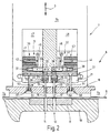
- the tool 6 used for this goes out in particular Figure 2 and 3 emerge.
- the lower tool 8 is a Formed die provided with two rows of holes 11, 12 is.
- the rows of holes are in corresponding rows 14, 15 ( Figure 4) arranged punch 16, 17 assigned to the belong to the upper tool 7.
- the punch 16, 17 are arranged in a punch holder plate 18 which has corresponding openings 19, 20.
- everyone Punches 16, 17 protrude through the opening assigned to it 19, 20 and is thereby axially movable.
- the punch 16, 17 sit with very little play in the corresponding cylindrical opening 19, 20.
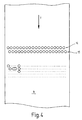
- FIG. 4 shows the punch 16, 17 of the two rows 14, 15 offset laterally against each other so that they refer to the transport direction T of the workpiece 9 overlap each other, or that they are on gap.
- the punch guide plate 18 is with one part of the upper tool 7 connected to the workpiece 9 or the die 8 or a press table holding this 19 touches down before the punch 16, 17 the Touch workpiece 9.
- the die guide plate 18th protruding punch 16, 17 are with their respective inner end preferably tensile and pressure resistant in one Stamp holding plate 21 held. This points to each punch 16, 17 on a stepped bore 22, 23, in each of which a plunger 24, 25 in the longitudinal direction of the Punch 16, 17 slidably held.
- the Punches 16, 17 lie with their top on the plane surface on the underside of the respective tappet 24, 25 on.
- the punch stamp 16, 17 are thus axial in the punch holder plate 21 between an active position in which they are on the lower tool 8 are advanced and a passive position adjustable in the lower tool 8 are moved away.
- the coil springs 28, 29 tension the Punches 16, 17 in front of their passive position.
- the bars 33, 34 are transverse to the working direction of the upper tool 7 slidably in a corresponding Leadership stored. You are there by a spring 37, 38th biased towards their locking position.
- Drive devices 39, 40 are provided, for example a solenoid 41, 42, an armature 43, 44 and a provided between the armature 43, 44 and the bolt 33, 34 Power transmission means 45, 46 are formed.
- the Magnetic coils 41, 42 can be controlled separately, see above that each punch 16, 17 has a bolt 33, 34 and assigned its own drive device 39, 40 is. It is also possible to lock 33, 34 on their Preload release position and they counter the preload by means of a drive device in the locking position to convict. If necessary, a preload can also be dispensed with if the one assigned to the bolt 33, 34 Drive device is designed to him in to move both directions.
- a relief device is common to all punches 16, 17 51 assigned to which as essential Element serves a stamp holding-down plate 52.
- the Drive devices 39, 40 are with a control device 47, 48 connected by a bus system and if necessary, appropriate drivers and decoders are formed.
- the Control device 47, 48 is designed such that each solenoid 41, 42 controlled individually can be. In addition, they are put together as desired Groups of solenoids can be controlled simultaneously.
- the hold-down plate 52 is by one or more Tie rods 53, 54 compliant with the punch guide plate 18 connected.
- the tie rods 53, 54 are located at the ends firmly in the hold-down plate 52 and extend parallel to the punch 16, 17 in corresponding Blind holes 55, 56 of the punch guide plate 18. In these blind holes 55, 56 sit on the bottom thereof supporting coil springs 57, 58 which hold the hold-down plate 52 on the tie rods 53, 54 on the punch guide plate 18 pull.
- the hold-down plate 52 also has bores 61, 62 through which Extensions of the plunger 24, 25 towards the latch 33, 34 extend. The extensions are each of a ring shoulder surrounded on which the hold-down plate 52nd is present.
- the hold-down plate 52 is in its lower one Position where it rests on the tappet holder plate 21, it pushes the plunger 24, 25 so far into the blind holes 22, 23 against the action of the coil springs 28, 29 a that the punch 16, 17 in the active position are and that the extensions of the plunger 24, 25 are the ways release for bolts 33, 34. These can therefore be against very low mechanical resistance from the coil springs 37, 38 or the magnetic coils 41, 42 are moved.
- the perforating press 1 described so far works as follows:
- the upper tool 7 is Perforating press 1 in its top dead center position.
- Upper tool 7 associated sheet metal holder 7a are disengaged with the workpiece 9.
- the stamp holding plate 21 carries. This results in a relative large distance between the punch holder plate 21 and the punch guide plate 18.
- the hold-down plate 52 is therefore all the way down pressed in contact with the punch holder plate 21.
- the hold-down plate 52 holds against the force of the Coil springs 28, 29 the plungers 24, 25 in the active position, i.e. in a position in which the punch 16, 17 protrude out of the punch guide plate 18 at most.
- the distance between the free end faces of the Tappets 24, 25 and the opposite contact surfaces 35, 36 is therefore maximum, so that the bolts 33, 34 easily into the space formed here and can be led out of this, in Figure 7, in which illustrates the movement diagram of the upper tool 7 this can be anywhere in the area A done.
- the control devices 47, 48 control the Magnetic coils 41, 42 in this range of movement of the plunger the perforating press 1 so that the punch 16, 17 the holes in the next down stroke of the ram should generate, locked in their advanced direction become.
- the latch 34 is in the locking position transferred by de-energizing the solenoid 42 becomes.
- the magnetic coil 41 is excited and holds the bolt 33 in release position.
- a new hole pattern can thus be defined in each stroke and punched out. This is shown schematically in FIG. 4 indicated. All conceivable hole positions are illustrated by dots for a portion of the workpiece 9. Holes are only punched out if the punch 17 in question is also locked. By Switching the relevant latch 33, 34 in successive Press strokes can in the given Any hole pattern can be obtained. The press can run continuously with a high number of strokes.
- the relief device 51 with that on the workpiece 9 or another abutment part 7a of the Tool 7 connected.
- the hold-down plate 52 with a separate Drive device to connect the hold-down plate 52 temporarily to the punch holding plate 21 presses or pretensions towards them.
- This drive device can be an electrical or fluid-operated drive device be. It then acts in the axial direction, i.e. in the direction corresponding to arrow 3.
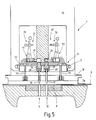
- FIG. 5 A further modified embodiment of the The perforating press 1 or the upper tool 7 is shown in FIG. 5 illustrated.
- the main difference to that The embodiment described above is in the drive of the bolt 33, 34.
- This is by a Fluid cylinder 71, 72 formed in which a piston 73, 74th is slidably mounted and sealed.
- the piston 73, 74 can be both single and double acting in one corresponding cylinder may be arranged.
- Figure 5 is illustrates a double-acting version.
- the piston position is controlled via the corresponding one Changeover directional control valves 75, 76, which can be electrically controlled, for example are.
- Changeover directional control valves 75, 76 which can be electrically controlled, for example are.
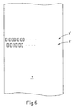
- the tappet guide plate 18, the tappet holder plate 21, the locking device 31, 32 and the relief device 51 can be designed as an exchangeable cassette be, for example, from the side into the tool 7 can be inserted. So one can in the simplest way Adaptation to different hole spacing or hole shapes be achieved. E.g. can instead of punches 16, 17 with a round cross section also three, four or polygonal punches are used, as in FIG. 6 is illustrated using two rows of tappets 14 ', 15', which are only shown here in part. In addition, the sheet metal transport on an air cushion to avoid damage.
- a press in particular a perforating press 1 provided with a tool 7 on which several punches 16, 17 are adjustable.
- To lock the Punches 16, 17 in the active position serve as locking devices 31, 32 to change the selection by a relief device 51 will be released if the punch 16, 17 out of engagement with the workpiece 9th and are within a certain safety margin this.
- the relief device enables a low-performance, yet quick adjustment of the Locking devices 31, 32 and thus a change the punch selection with every press stroke also at high-speed presses.
- Preloading the punch 16, 17 on their passive position allows the Avoidance of contact between passive punches 16 and the workpiece 9 during the press stroke. This avoids workpiece damage.
Landscapes
- Engineering & Computer Science (AREA)
- Mechanical Engineering (AREA)
- Life Sciences & Earth Sciences (AREA)
- Forests & Forestry (AREA)
- Perforating, Stamping-Out Or Severing By Means Other Than Cutting (AREA)
- Presses And Accessory Devices Thereof (AREA)
- Press Drives And Press Lines (AREA)
Abstract
Eine Presse, insbesondere eine Perforierpresse (1)
ist mit einem Werkzeug (7) versehen, an dem mehrere Lochstempel
(16, 17) verstellbar gelagert sind. Zur Arretierung
der Lochstempel (16, 17) in Aktivposition dienen
Arretiereinrichtungen (31, 32), die zum Verändern der
Auswahl durch eine Entlastungseinrichtung (51) freigegebenen
werden, wenn die Lochstempel (16, 17) außer Eingriff
mit dem Werkstück (9) sind und sich in einem gewissen
Sicherheitsabstand zu diesem befinden. Die Entlastungseinrichtung
ermöglicht eine leistungsarme und
dennoch schnelle Verstellung der Arretiereinrichtungen
(31, 32) und somit eine Veränderung der Lochstempelauswahl
bei jedem Pressenhub auch bei schnelllaufenden
Pressen. Eine Vorspannung der Lochstempel (16, 17) auf
ihre Passivposition hin gestattet die Vermeidung von
Berührungen zwischen passiven Lochstempeln (16) und dem
Werkstück (9) während des Pressenhubs. Dies vermeidet
Werkstückbeschädigungen.

Description
Die Erfindung betrifft eine Presse mit einem Werkzeug, an dem verstellbar gelagerte Werkzeugteile, bspw. Stempel vorhanden sind.The invention relates to a press with a tool, on the adjustable tool parts, e.g. Stamps are present.
Insbesondere zum Perforieren von Blechen oder anderweitigem Flachmaterial sind Pressen in Gebrauch, die einen mit einem Antrieb verbundenen Pressenstößel aufweisen, an dem ein mit mehreren Lochstempeln versehenes Oberwerkzeug angeordnet ist. Unter dem Pressenstößel ist ein Pressentisch mit einem Unterwerkzeug angeordnet, dass entsprechende den Lochstempeln zugeordnete Öffnungen aufweist. Eine Vorschubeinrichtung dient dazu, einen Blechstreifen oder ein anderweitiges Werkstück schrittweise durch das Werkzeug zu fördern, wenn dieses offen ist, d.h. die Lochstempel nicht mit dem Unterwerkzeug und dem Werkstück in Eingriff stehen. Die Lochstempel sind bspw. in einer Reihe angeordnet, die quer zu der Vorschubrichtung ausgerichtet ist. Bei jedem Stanzschritt entsteht somit eine vollständige Lochreihe in dem Werkstück.In particular for perforating sheet metal or otherwise Flat material presses are in use that have a press ram connected to a drive, on which there is one with several punches Upper tool is arranged. Is under the press ram arranged a press table with a lower tool that corresponding openings assigned to the punch having. A feed device is used to Sheet metal strips or another workpiece step by step to promote through the tool if this is open is, i.e. the punches are not with the lower tool and engage the workpiece. The punch stamps are For example, arranged in a row that is transverse to the feed direction is aligned. With every punching step This creates a complete row of holes in the workpiece.
Bei einigen Anwendungsfällen kann es jedoch zu wünschen oder zweckmäßig sein, anstelle einer vollständigen Lochreihe nur eine unterbrochene Reihe zu stanzen. Hier wird es erforderlich, einzelne Lochstempel unwirksam zu machen. Bei empfindlichen Blechen wie bspw. Aluminiumblechen oder polierten Blechen, oder generell bei Anwendungen, bei denen es auf optische Aspekte ankommt, ist häufig zu wünschen, dass das Blech oder das sonstige Werkstück nach dem Bearbeitungsvorgang im Wesentlichen unberührt erscheint. Keinesfalls sind Marken, Kratzer oder sonstwelche Oberflächenbeschädigungen hinzunehmen. Wenn die Lochstempel als beweglich oder verstellbar ausgebildete Teile des Werkzeugs verstellt werden, muss dies so erfolgen, dass an den passiv gestellten Lochstempelpositionen keine Werkstückbeschädigungen erfolgen. Soll das Lochmuster während des Betriebs der Presse geändert werden, ist es darüberhinaus erforderlich, eine Presse zu schaffen, die eine entsprechende Verstellung des Werkzeugs während des Betriebs der Presse gestattet.In some use cases, however, it can wish or be useful, instead of a complete To punch a row of holes only an interrupted row. Here it becomes necessary to make individual punches ineffective close. For sensitive sheets such as aluminum sheets or polished sheets, or generally in applications, where optical aspects are important often to wish that the sheet or the other Workpiece after the machining process essentially appears untouched. In no way are marks, scratches or accept any other surface damage. If the punch is moveable or adjustable trained parts of the tool must be adjusted this is done so that at the passively placed punch positions no workpiece damage. Should the hole pattern during the operation of the press be changed, it is also necessary to Press to create the appropriate adjustment of the tool while the press is operating.
Davon ausgehend ist es Aufgabe der Erfindung eine Presse zu schaffen, die eine Änderung der an einem Werkstück vorzunehmenden Bearbeitungsoperation während des Betriebs der Presse gestattet.Based on this, it is an object of the invention Press to create a change to a workpiece machining operation to be performed during the Press operation permitted.
Diese Aufgabe wird mit der Presse gelöst, die die
Merkmale des Patentanspruchs 1 aufweist.This task is solved with the press, which the
Features of
Die erfindungsgemäße Presse weist ein Werkzeug auf, das aus Oberwerkzeug und Unterwerkzeug besteht. Diese sind bspw. dadurch aufeinander zu und voneinander weg bewegbar, dass das Oberwerkzeug an einem Pressenstößel befestigt und mit diesem hin- und hergehend bewegt und das Unterwerkzeug auf einem Pressentisch ortsfest gelagert ist. Prinzipiell sind jedoch auch andere kinematische Abläufe und Zuordnungen von Einzelbewegungen möglich. Bspw. kann allein oder zusätzlich das Unterwerkzeug bewegt werden.The press according to the invention has a tool which consists of upper tool and lower tool. This are, for example, towards and away from each other that the upper tool can be moved on a press ram attached and moved back and forth with this and the lower tool is fixed on a press table is. In principle, however, there are also other kinematic ones Sequences and assignments of individual movements possible. E.g. can use the lower tool alone or in addition be moved.
Das Oberwerkzeug trägt wenigstens zwei, vorzugsweise jedoch deutlich mehr als zwei Werkzeugteile, vorzugsweise Stempel, insbesondere Lochstempel, die verstellbar angeordnet sind. In bevorzugter Ausführungsform sind die Stempel im Abstand parallel zueinander etwa rechtwinklig zu dem Blech oder sonstigem Werkstück so gehalten, dass ihre Längsrichtung mit der Bewegungsrichtung des Oberwerkzeugs übereinstimmt. Die Verstellrichtung der Stempel stimmt hier mit der Bewegungsrichtung des Oberwerkzeugs überein. Die Stempel können in eine vorgeschobene Position überführt und in dieser verriegelt werden. Dazu dient eine entsprechende Arretiereinrichtung. Außerdem können die Stempel freigegeben werden, wodurch sie in Passivposition überführbar sind.The upper tool carries at least two, preferably however, significantly more than two tool parts, preferably Stamp, in particular punch, which are arranged adjustable are. In a preferred embodiment, the Stamps parallel to each other approximately at right angles to the sheet or other workpiece so that their longitudinal direction with the direction of movement of the upper tool matches. The direction of adjustment of the stamp agrees with the direction of movement of the upper tool match. The stamp can be in an advanced position transferred and locked in this. To serves a corresponding locking device. Furthermore the stamps can be released, making them in Passive position can be transferred.
An dem Oberwerkzeug ist eine Entlastungseinrichtung vorgesehen, die die Stempel in ihre Aktivposition vorspannt. Damit wird der Weg für die Arretiereinrichtung freigegeben und die Arretiereinrichtung muss keine Stellarbeit zum Bewegen der Stempel leisten. Außerdem werden Reibungseinflüsse minimiert. Dies gestattet ein sehr schnelles Umschalten der Arretiereinrichtung von einem Zustand, in dem der zugeordnete Stempel in Aktivposition verriegelt ist, in einen entriegelten Zustand und zurück mit leistungsschwachen Antrieben. Bspw. kann ein quer zu dem Stempel beweglicher Riegel in einen von der Entlastungseinrichtung freigehaltenen Zwischenraum ein- und ausfahren ohne von dem Stempel belastet, bspw. festgeklemmt zu werden. Dies gilt auch für andere Ausführungsformen einer Arretiereinrichtung, die bspw. auch durch einen Nocken gebildet sein kann. Auch dieser lässt sich wesentlich leichter drehen oder schwenken, wenn ein entsprechendes Kurvenfolgermittel, das auf den Stempel wirkt oder mit diesem verbunden ist, nicht an die Kurvenfläche des Nockens angepresst ist.There is a relief device on the upper tool provided, which biases the stamp in its active position. This is the way for the locking device released and the locking device does not have to be operated afford to move the stamp. Also be The effects of friction are minimized. This allows a very quick switching of the locking device from one State in which the assigned stamp is in the active position is locked, in an unlocked state and back with underperforming drives. E.g. can be a cross to the stamp movable latch into one of the relief device keep free space in and extend without being loaded by the punch, for example to become. This also applies to other embodiments a locking device, for example, also by a cam can be formed. This too can be turn or pivot much easier if a corresponding curve follower means that on the stamp acts or is connected to it, not to the curve surface the cam is pressed.
Die Entlastungseinrichtung ermöglicht somit eine Minimierung des erforderlichen Bauvolumens der Arretiereinrichtung und eine evtl. dieser zugeordneten Antriebseinrichtung. Dies gestattet wiederum die Anordnung der Stempel in geringen Abständen zueinander. Damit können sehr enge Lochmuster auch bei kleinen Stempeldurchmessern erzeugt werden.The relief device thus enables Minimization of the required volume of the locking device and possibly a drive device assigned to this. This in turn allows the arrangement of the Stamps at close intervals. So that can very tight hole pattern even with small punch diameters be generated.
Darüberhinaus ermöglicht die Entlastungseinrichtung eine solche Leichtgängigkeit der Arretiereinrichtung, dass eine Verstellung auch bei kleinen Verstellantrieben in sehr kurzer Zeit möglich ist. Dadurch können ein oder mehrere Stempel in äußerst kurzer Zeit von passiv zu aktiv und zurück umgeschaltet werden. Dies hat insbesondere für die Erzeugung von Lochmustern Bedeutung, bei denen nicht längere Zeit mit ein und derselben Auswahl aktiver und passiver Stempel gearbeitet wird. Soll bspw. bei jedem Pressenhub ein neues Lochmuster erzeugt werden, erfordert dies eine Veränderung der Auswahl der Stempel bei jedem Pressenhub. Die dafür zur Verfügung stehende Zeit ist bei schnelllaufenden Pressen nicht sehr groß. Jedoch reicht die Zeit selbst bei leistungsschwachen Antrieben zur Verstellung aus, wenn aie Entlastungseinrichtung die Arretiereinrichtung der Stempel entlastet, indem sie diese auf ihre Aktivposition hin vorspannt. Die Energie zur Bewegung der Stempel aus ihrer Aktiv- in ihre Passivposition und umgekehrt, wird nicht der Arretiereinrichtung bzw. ihrer Antriebseinrichtung entnommen.In addition, the relief device enables such ease of movement of the locking device, that adjustment even with small actuators is possible in a very short time. This allows one or multiple stamps in a very short time from passive to active and switched back. This has in particular importance for the generation of hole patterns, at not for long periods with the same selection active and passive stamp. For example, a new hole pattern is generated with each press stroke, this requires a change in the choice of stamp with every press stroke. The available one Time is not very long with high-speed presses. However, there is enough time even for those with poor performance Drives for adjustment if aie the relief device the locking device relieves the stamp, by biasing them towards their active position. The Energy to move the stamp from its active into its Passive position and vice versa, will not be the locking device or taken from their drive device.
Prinzipiell ist es möglich, mehrere Stempel zu Gruppen zusammenzufassen, die von einer gemeinsamen Arretiereinrichtung gesperrt und freigegeben werden. Die größtmögliche Variabilität wird jedoch erhalten, wenn jedem Stempel genau eine Arretiereinrichtung zugeordnet ist.In principle it is possible to add several stamps Summarize groups by a common one Locking device can be locked and released. The However, the greatest possible variability is obtained if exactly one locking device is assigned to each stamp is.
Bei einer bevorzugten Ausführungsform ist jedem verstellbaren Werkzeugteil oder Stempel ein Federmittel zugeordnet, mit dem der Stempel auf seine Passivposition hin vorgespannt ist. Das Federmittel wird zeitweilig von der Entlastungseinrichtung überwunden, um den Stempel bspw. in der Nähe des oberen Totpunkts des Pressenstößels in Aktivposition zu bringen, so dass die Arretiereinrichtung den Aktivzustand lastfrei einschalten kann. Gibt die Entlastungseinrichtung dann während der Abwärtsbewegung des Pressenstößels die Stempel frei, bleiben die arretierten Stempel in Aktivposition, während die nichtarretierten Stempel durch das Federmittel in Passivposition rücküberführt werden. Während die aktiven Stempel mit dem Werkstück in Eingriff kommen, erreichen die von dem Federmittel in Passivposition gehaltenen Stempel das Werkstück nicht. Sie berühren dieses nicht und können somit auch keine Beschädigungen, Kratzer, Macken oder ähnliches verursachen.In a preferred embodiment, everyone is adjustable tool part or stamp a spring means assigned with which the stamp on its liability position is biased. The spring means is temporarily from the relief device overcome the stamp For example, near the top dead center of the press ram bring into active position so that the locking device can switch on the active state without load. Give the Relief device then during the downward movement the stamp of the press ram free, the locked remain Stamp in active position while the non-arrested Stamp by the spring means in passive position be returned. While the active stamp with the Workpiece come into engagement, that of the Spring means held in passive position Workpiece not. You do not touch it and can thus no damage, scratches, quirks or cause something similar.
Die Arretiereinrichtung weist vorzugsweise ein Sperrelement, bspw. einen Riegel auf, das bzw. der orthogonal zu der Verstellrichtung des Stempels zu bewegen ist. Die für die Axialverstellung der Stempel erforderliche Kraft wird durch die Entlastungseinrichtung aufgebracht und aus der Bewegung des Pressenstößels abgeleitet. Auch dies minimiert die von der Arretiereinrichtung bzw. deren Antriebseinrichtung aufzubringende mechanische Arbeit mit den obengenannten Vorteilen.The locking device preferably has a Locking element, for example. A latch, the or the orthogonal to move the direction of the stamp is. The one required for the axial adjustment of the stamp Force is applied by the relief device and derived from the movement of the press ram. This also minimizes that of the locking device or their drive device to be applied mechanical Work with the advantages mentioned above.
Dem Federmittel zur Vorspannung der Stempel auf ihre Passivposition hin, kann ein Hubbegrenzungsmittel zugeordnet sein, das ein Herausziehen des Stempels aus dem Oberwerkzeug über eine Maximalposition hinaus, die im Wesentlicher seiner Aktivposition entspricht, verhindert. Damit kann bspw. bei Perforierpressen verhindert werden, dass einzelne Lochstempel, die reibungsmäßig in dem perforierten Werkstück gehalten sind, soweit aus dem Oberwerkzeug herausgezogen werden, dass die einzelnen Federn der Lochstempel vollständig komprimiert werden. Außerdem wurden die Lochstempel zwangsgeführt aus dem Werkstück gezogen.The spring means to preload the stamp on your Passive position, a stroke limiting means can be assigned be that pulling the stamp out of the Upper tool beyond a maximum position that in the Mainly corresponds to his active position, prevented. For example, in the case of perforating presses that single punch that runs smoothly in the perforated workpiece are held as far from the Top tool that individual are pulled out Springs of the punch are fully compressed. In addition, the punches were forced out of the Workpiece pulled.
Die Ansteuerung der einzelnen Riegel oder sonstigen Sperrelement der Arretiereinrichtung kann elektrisch oder mit einem Fluid, bspw. pneumatisch erfolgen. Durch die Entlastung der Sperrelemente (Riegel) während ihrer Verstellung kann auf eine präzise Führung der Sperrelemente verzichtet werden. Es genügt eine schwimmende Lagerung die sicherstellt, dass das entsprechende Sperrelement in Sperrposition den Stempel in Aktivposition verriegelt. Dies kann durch entsprechende Anlageflächen erfolgen, an denen das Sperrelement in Sperrposition anliegt.The control of the individual bars or other Locking element of the locking device can be electrical or with a fluid, for example pneumatically. Through the Relief of the locking elements (bolts) during their Adjustment can be based on precise guidance of the locking elements to be dispensed with. A floating is sufficient Storage which ensures that the corresponding locking element in the blocking position the stamp in the active position locked. This can be achieved through appropriate contact surfaces take place on which the locking element in the locked position is present.
Die Stempel, die Ärretiereinrichtung und die Entlastungseinrichtung können als austauschbare Kassette ausgebildet sein. Dadurch können auf einfache Weise unterschiedliche Lochzahlen-Durchmesser oder -Formen erzeugt werden.The stamp, the locking device and the relief device can be used as a replaceable cassette be trained. This allows you to easily different hole number diameters or shapes be generated.
Weitere Einzelheiten vorteilhafter Ausführungsformen der Erfindung ergeben sich aus der Zeichnung oder der Beschreibung und können Gegenstand von Unteransprüchen sein.Further details of advantageous embodiments the invention result from the drawing or the Description and subject of subclaims be.
In der Zeichnung sind Ausführungsbeispiele der
Erfindung veranschaulicht. Es zeigen:
In Figur 1 ist eine Perforierpresse 1 im Ganzen
schematisiert veranschaulicht. Die Perforierpresse 1
weist ein in einem Pressengestell 2 in einer durch einen
Pfeil 3 angedeuteten Richtung hin- und hergehend angetriebenen
Stößel 4 auf. Zwischen dem Stößel 4 und einem
Pressentisch 5 ist ein Werkzeug 6 angeordnet, zu dem ein
Oberwerkzeug 7 und ein Unterwerkzeug 8 gehören. Zwischen
dem Oberwerkzeug 7 und dem Unterwerkzeug 8 wird ein
Werkstück 9, bspw. ein Blech oder ein aus einem anderweitigen
Material bestehendes Flächengebilde, geführt.
Dieses wird durch die Presse mit einem Lochmuster versehen,
das von einer nicht weiter veranschaulichten
Steuereinheit vorgebbar ist. Das Lochmuster kann bspw.
über einen Scanner oder eine sonstige Eingabeeinrichtung
von einer Vorlage abgetastet sein und wird mittels der
Perforierpresse 1 in das Werkstück 9 eingestanzt.A perforating
Das dazu verwendet Werkzeug 6 geht insbesondere aus
Figur 2 und 3 hervor. Das Unterwerkzeug 8 wird durch eine
Matrize gebildet, die mit zwei Lochreihen 11, 12 versehen
ist. Den Lochreihen sind in entsprechenden Reihen 14, 15
(Figur 4) angeordnete Lochstempel 16, 17 zugeordnet, die
zu dem Oberwerkzeug 7 gehören. Die Lochstempel 16, 17
sind in einer Lochstempelhalterplatte 18 angeordnet, die
dazu entsprechende Öffnungen 19, 20 aufweist. Jeder
Lochstempel 16, 17 durchragt die ihm zugeordnete Öffnung
19, 20 und ist dadurch axial beweglich geführt. Die Lochstempel 16,
17 sitzen dabei mit recht geringem Spiel in den entsprechenden
zylindrischen Öffnung 19, 20. Wie aus Figur 4
hervorgeht, sind die Lochstempel 16, 17 der beiden Reihen
14, 15 dabei seitlich gegeneinander versetzt, so dass sie
sich bezogen auf die Transportrichtung T des Werkstücks 9
gegenseitig überlappen, bzw. dass sie auf Lücke stehen.The
Die Lochstempelführungsplatte 18 ist mit einem Teil
des Oberwerkzeugs 7 verbunden, der auf dem Werkstück 9
oder der Matrize 8 oder einem dieser haltenden Pressentisch
19 aufsetzt, bevor die Lochstempel 16, 17 das
Werkstück 9 berühren. Die die Stempelführungsplatte 18
durchragenden Lochstempel 16, 17 sind mit ihrem jeweiligen
inneren Ende vorzugsweise zug- und druckfest in einer
Stempelhalteplatte 21 gehalten. Diese weist dazu für
jeden Lochstempel 16, 17 eine Stufenbohrung 22, 23 auf,
in der jeweils ein Stößel 24, 25 in Längsrichtung des
Lochstempels 16, 17 verschiebbar gehalten sitzt. Die
Lochstempel 16, 17 liegen mit ihrer Oberseite an der
unterseitigen Planfläche des jeweiligen Stößels 24, 25
an. Bedarfsweise können sie auch miteinander verbunden
sein.Dabei bildet eine an dem jeweiligen inneren Ende des
Lochstempels 16, 17 gehaltene Scheibe 26, 27 oder eine
Ringschulter ein Anlagemittel für eine Schraubenfeder 28,
29, die sich mit ihrem anderen Ende an dem Boden der
jeweiligen Stufenbohrung 22, 23 abstützt. Die Lochstempel
16, 17 sind somit in der Lochstempelhalterplatte 21 axial
zwischen einer Aktivposition, in der sie auf das Unterwerkzeug
8 hin vorgeschoben sind, und einer Passivposition
verstellbar in der sie von dem Unterwerkzeug 8
wegbewegt sind. Die Schraubenfedern 28, 29 spannen die
Lochstempel 16, 17 auf ihre Passivposition hin vor.The
Um die Lochstempel 16, 17 in ihrer in Figur 2 veranschaulichten
Aktivposition zu verriegeln, ist an dem
Oberwerkzeug 7 für jeden Lochstempel 16, 17 eine Arretierungseinrichtung
31, 32 vorgesehen. Zu dieser gehört
jeweils ein quer zu dem Lochstempel 16, 17 bewegbarer
Riegel 23, 34, der zwischen eine Anlagefläche 35, 36 und
eine endseitige Stirnfläche des Stößels 24, 25 einschiebbar
ist. Ist der Riegel 33, 34 in den Zwischenraum eingeschoben,
blockiert er den Lochstempel 16, 17 in seiner
Aktivposition. In Figur 2 ist der Lochstempel 17 in
Aktivposition arretiert veranschaulicht, während der
Lochstempel 16 ebenfalls in Aktivposition, jedoch von der
Arretierungseinrichtung 31 nicht arretiert veranschaulicht
ist. Around the
Die Riegel 33, 34 sind quer zu der Arbeitsrichtung
des Oberwerkzeugs 7 verschiebbar in einer entsprechenden
Führung gelagert. Sie sind dabei durch eine Feder 37, 38
auf ihre Arretierungsposition hin vorgespannt. Um den
jeweiligen Riegel 33, 34 aus dieser herauszuführen, sind
Antriebseinrichtungen 39, 40 vorgesehen, die bspw. durch
eine Magnetspule 41, 42, einen Anker 43, 44 und ein
zwischen dem Anker 43, 44 und dem Riegel 33, 34 vorgesehenes
Kraftübertragungsmittel 45, 46 gebildet sind. Die
Magnetspulen 41, 42 sind dabei separat ansteuerbar, so
dass jedem Lochstempel 16, 17 jeweils ein Riegel 33, 34
und eine eigene Antriebseinrichtung 39, 40 zugeordnet
ist. Es ist auch möglich die Riegel 33, 34 auf ihre
Freigabepositon vorzuspannen und die sie gegen die Vorspannung
mittels einer Antriebseinrichtung in Arretierungsposition
zu überführen. Bedarfsweise kann auf eine Vorspannung
auch verzichtet werden, wenn die dem Riegel 33, 34 zugeordnete
Antriebseinrichtung dazu ausgelegt ist, ihn in
beide Richtungen zu bewegen.The
Allen Lochstempeln 16, 17 gemeinsam ist eine Entlastungseinrichtung
51 zugeordnet, zu der als wesentliches
Element eine Stempelniederhalterplatte 52 dient. Die
Antriebseinrichtungen 39, 40 sind mit einer Ansteuereinrichtung
47, 48 verbunden, die durch ein Busssystem und
ggfs. entsprechende Treiber und Dekoder gebildet ist. Die
Ansteuereinrichtung 47, 48 ist dabei so ausgelegt, dass
jede Magnetspule 41, 42 gezielt einzeln angesteuert
werden kann. Außerdem sind beliebig zusammengestellt
Gruppen von Magnetspulen gleichzeitig ansteuerbar.A relief device is common to all
Diese ist bezüglich der Richtung 3 begrenzt bewegbar.
Die Niederhalterplatte 52 ist durch ein oder mehrere
Zuganker 53, 54 nachgiebig mit der Lochstempelführungsplatte
18 verbunden. Die Zuganker 53, 54 sitzen endseitig
fest in der Niederhalterplatte 52 und erstrecken sich
parallel zu den Lochstempeln 16, 17 in entsprechende
Sackbohrungen 55, 56 der Stempelführungsplatte 18. In
diesen Sackbohrungen 55, 56 sitzen sich an deren Boden
abstützende Schraubenfedern 57, 58, die die Niederhalterplatte
52 über die Zuganker 53, 54 auf die Lochstempelführungsplatte
18 hin ziehen. Die Niederhalterplatte 52
weist außerdem Bohrungen 61, 62 auf, durch die sich
Fortsätze der Stößel 24, 25 auf die Riegel 33, 34 hin
erstrecken. Die Fortsätze sind jeweils von einer Ringschulter
umgeben, an denen die Niederhalterplatte 52
anliegt. Ist die Niederhalterplatte 52 in ihrer unteren
Position, an der sie an der Stößelhalterplatte 21 anliegt,
drückt sie die Stößel 24, 25 so weit in die Sackbohrungen
22, 23 gegen die Wirkung der Schraubenfedern
28, 29 ein dass die Lochstempel 16, 17 in Aktivposition
sind und dass die Fortsätze der Stößel 24, 25 die Wege
für die Riegel 33, 34 freigeben. Diese können somit gegen
sehr geringen mechanischen Widerstand von den Schraubenfedern
37, 38 oder den Magnetspulen 41, 42 bewegt werden.This can be moved to a limited extent with respect to
Die insoweit beschriebene Perforierpresse 1 arbeitet
wie folgt:The perforating
Zur Erläuterung der Arbeitsweise der Perforierpresse
1 wird im Folgenden ein einziger Arbeitshub derselben
verfolgt. In Figur 2 befindet sich das Oberwerkzeug 7 der
Perforierpresse 1 in seiner oberen Totpunktlage. Zu dem
Oberwerkzeug 7 gehörige Blechhalter 7a sind außer Eingriff
mit dem Werkstück 9. In relativ höherer Position
befindet sich ein gegen den Teil 7a des Oberwerkzeugs 7
beweglicher Teil 7b des Oberwerkzeugs 7, der die Stempelhalteplatte
21 trägt. Es ergibt sich dadurch ein relativ
großer Abstand zwischen der Lochstempelhalteplatte 21 und
der Lochstempelführungsplatte 18. Über die Zuganker 53,
54 wird die Niederhalterplatte 52 deshalb ganz nach unten
in Anlage mit der Lochstempelhalteplatte 21 gedrückt.
Dabei hält die Niederhalterplatte 52 gegen die Kraft der
Schraubenfedern 28, 29 die Stößel 24, 25 in Aktivposition,
d.h. in einer Position in der die Lochstempel 16,
17 maximal aus der Lochstempelführungsplatte 18 herausragen.To explain how the perforating press works
1 is a single working stroke of the same
tracked. In Figure 2, the
Der Abstand zwischen den freien Stirnseiten der
Stößel 24, 25 und der gegenüberliegenden Anlageflächen
35, 36 ist deshalb maximal, so dass die Riegel 33, 34
leicht in den hier ausgebildeten Zwischenraum hinein und
aus diesem herausgeführt werden können, in Figur 7, in
der das Bewegungsdiagramm des Oberwerkzeugs 7 veranschaulicht
ist, kann dies an beliebiger Stelle in dem Bereich
A erfolgen. Die Steuereinrichtungen 47, 48 steuern die
Magnetspulen 41, 42 in diesen Bewegungsbereich des Stößels
der Perforierpresse 1 nun so an, dass die Lochstempel
16, 17 die im nächsten Abwärtshub des Stößels Löcher
erzeugen sollen, in ihrer vorgeschobenen Richtung arretiert
werden. Dazu wird bspw. der Riegel 34 in Arretierstellung
überführt, indem die Magnetspule 42 entregt
wird. Die Magnetspule 41 ist erregt und hält den Riegel
33 in Freigabeposition.The distance between the free end faces of the
Während des nun folgenden Abwärtshubs des Oberwerkzeugs
7, setzt zunächst der Niederhalter 7a auf dem
Werkstück 9 auf (Punkt B in Figur 7), wobei seine Abwärtsbewegung
hier endet. Jedoch bewegt sich der Teil 7b
des Oberwerkzeugs 7 weiter nach unten, wodurch sich der
Abstand zwischen der Lochstempelhalterplatte 21 und der
Lochstempelführungsplatte 18 vermindert. Die relativ
kurzhubigen Schraubenfedern 57, 58 ziehen die Niederhalterplatte
52 nun nicht länger nach unten. Während der
Lochstempel 17 von dem Riegel 34 in Aktivposition arretiert
ist, gilt dies nicht für den Lochstempel 16. Dieser
wird von seiner Schraubenfeder 28 nun in seine Passivposition
gedrückt, d.h. sein Stößel 24 bleibt mit seiner
Ringschulter in Anlage mit der Niederhalteplatte 52,
während der Stößel 25 durch den Riegel 34 nach unten
gedrückt wird. Der Lochstempel 17 durchdringt deshalb das
Werkstück 9 und stanzt ein Loch aus, während der Lochstempel
16 das Werkstück 9 an keiner Stelle berührt.
Während der Zeitspanne C in der der Niederhalter 7a auf
dem Werkstück 9 aufsitzt, schwebt der Lochstempel 16 über
dem Werkstück 9.During the following downward stroke of the
Während des Rückhubs hebt zu Ende des Zeitintervalls
C der Niederhalter 7a von dem Werkstück ab und drückt mit
seiner Niederhalterplatte 15 alle Lochstempel 16, 17 in
Aktivposition und zwar unabhängig davon, ob sie aktiv
sein sollen oder nicht. Durch entsprechende Ansteuerung
der Ansteuereinrichtung 47, 48 bzw. der Magnetspulen 41,
42 kann eine neue Auswahl von aktiven Lochstempeln 16, 17
festgelegt werden. Im nächsten Abwärtshub fahren zunächst
alle Lochstempel 16, 17 nach unten, wobei die nichtaktiv
geschalteten Lochstempel stoppen, nachdem der Niederhalter
7a auf dem Werkstück 9 aufgesetzt hat während sich
die aktiven Lochstempel 17 weiterbewegen und hier noch
stanzen.During the return stroke lifts at the end of the time interval
C the hold-down 7a from the workpiece and presses with
its hold-
In jedem Hub kann somit ein neues Lochmuster festgelegt
und ausgestanzt werden. Dies ist in Figur 4 schematisch
angedeutet. Alle denkbaren Lochpositionen sind
durch Punkte für einen Abschnitt des Werkstücks 9 veranschaulicht.
Ausgestanzt werden Löcher jedoch nur, wenn
der betreffende Lochstempel 17 auch arretiert ist. Durch
Umschalten der betreffenden Riegel 33, 34 in aufeinanderfolgenden
Pressenhüben können in dem vorgegebenen
Raster beliebige Lochmuster erhalten werden. Die Presse
kann dabei kontinuierlich mit hoher Hubzahl laufen.A new hole pattern can thus be defined in each stroke
and punched out. This is shown schematically in FIG. 4
indicated. All conceivable hole positions are
illustrated by dots for a portion of the
Bei der vorstehend beschriebenen Ausführungsform ist
die Entlastungseinrichtung 51 mit dem auf dem Werkstück 9
oder einem sonstigen Widerlager aufsetzenden Teil 7a des
Werkzeugs 7 verbunden. Abweichend davon ist es auch
möglich, die Niederhalterplatte 52 mit einer gesonderten
Antriebseinrichtung zu verbinden, die die Niederhalterplatte
52 zeitweilig an die Lochstempelhalteplatte 21
andrückt oder auf diese hin vorspannt. Diese Antriebseinrichtung
kann eine elektrische oder fluidbetätigte Antriebseinrichtung
sein. Sie wirkt dann in Axialrichtung,
d.h. in mit dem Pfeil 3 übereinstimmender Richtung.In the embodiment described above
the
Ein weiter abgewandeltes Ausführungsbeispiel der
Perforierpresse 1 bzw. des Oberwerkzeugs 7 ist in Figur 5
veranschaulicht. Der wesentliche Unterschied zu dem
vorstehend beschriebenen Ausführungsbeispiel besteht in
dem Antrieb der Riegel 33, 34. Dieser ist durch einen
Fluidzylinder 71, 72 gebildet, in dem ein Kolben 73, 74
verschiebbar und abgedichtet gelagert ist. Der Kolben 73,
74 kann sowohl einfach- als auch doppeltwirkend in einem
entsprechenden Zylinder angeordnet sein. In Figur 5 ist
eine doppeltwirkende Ausführung veranschaulicht. Die
Steuerung der Kolbenposition erfolgt über entsprechende
Umschalt-Wegeventile 75, 76, die bspw. elektrisch steuerbar
sind. Ebenso ist es jedoch möglich die Kolben 73, 74
mittels einer Feder auf eine Position hin vorzuspannen.
Ansonsten gilt die vorstehende Beschreibung entsprechend.A further modified embodiment of the
Die Stößelführungsplatte 18, die Stößelhalterplatte
21, die Arretiereinrichtung 31, 32 und die Entlastungseinrichtung
51 können als auswechselbare Kassette ausgebildet
sein, die bspw. von der Seite her in das Werkzeug
7 einschiebbar ist. So kann auf einfachste Weise eine
Anpassung an unterschiedliche Lochabstände oder Lochformen
erzielt werden. Bspw. können anstelle von Lochstempeln
16, 17 mit rundem Querschnitt auch drei, vier oder
mehreckige Lochstempel Anwendung finden, wie in Figur 6
anhand zweier Stößelreihen 14', 15' veranschaulicht ist,
die hier lediglich ausschnittsweise dargestellt sind.
Außerdem kann der Blechtransport auf einem Luftpolster
erfolgen, um Beschädigungen zu vermeiden.The
Eine Presse, insbesondere eine Perforierpresse 1 ist
mit einem Werkzeug 7 versehen, an dem mehrere Lochstempel
16, 17 verstellbar gelagert sind. Zur Arretierung der
Lochstempel 16, 17 in Aktivposition dienen Arretiereinrichtungen
31, 32, die zum Verändern der Auswahl durch
eine Entlastungseinrichtung 51 freigegebenen werden, wenn
die Lochstempel 16, 17 außer Eingriff mit dem Werkstück 9
sind und sich in einem gewissen Sicherheitsabstand zu
diesem befinden. Die Entlastungseinrichtung ermöglicht
eine leistungsarme und dennoch schnelle Verstellung der
Arretiereinrichtungen 31, 32 und somit eine Veränderung
der Lochstempelauswahl bei jedem Pressenhub auch bei
schnelllaufenden Pressen. Eine Vorspannung der Lochstempel
16, 17 auf ihre Passivposition hin gestattet die
Vermeidung von Berührungen zwischen passiven Lochstempeln
16 und dem Werkstück 9 während des Pressenhubs. Dies
vermeidet Werkstückbeschädigungen.A press, in particular a perforating
Claims (12)
Applications Claiming Priority (2)
| Application Number | Priority Date | Filing Date | Title |
|---|---|---|---|
| DE19825843 | 1998-06-10 | ||
| DE19825843A DE19825843C2 (en) | 1998-06-10 | 1998-06-10 | Perforating press with single punch control |
Publications (2)
| Publication Number | Publication Date |
|---|---|
| EP0963802A2 true EP0963802A2 (en) | 1999-12-15 |
| EP0963802A3 EP0963802A3 (en) | 2001-04-18 |
Family
ID=7870464
Family Applications (1)
| Application Number | Title | Priority Date | Filing Date |
|---|---|---|---|
| EP99110929A Withdrawn EP0963802A3 (en) | 1998-06-10 | 1999-06-04 | Perforating press with drive system for one punch |
Country Status (3)
| Country | Link |
|---|---|
| EP (1) | EP0963802A3 (en) |
| CZ (1) | CZ202999A3 (en) |
| DE (1) | DE19825843C2 (en) |
Cited By (4)
| Publication number | Priority date | Publication date | Assignee | Title |
|---|---|---|---|---|
| WO2009101224A1 (en) | 2008-02-15 | 2009-08-20 | Eisen Xxi, S.L. | Automatic machine for punching and cutting wheel rims |
| ITVE20130049A1 (en) * | 2013-09-20 | 2015-03-21 | Dallan Spa | PUNCHING HEAD FOR PUNCHING MACHINES.- |
| CN104626373A (en) * | 2014-12-22 | 2015-05-20 | 中国电子科技集团公司第二研究所 | High-speed punching unit for low-temperature cofired ceramics |
| IT202200017547A1 (en) * | 2022-08-24 | 2024-02-24 | Corrada Spa | DEVICE FOR ELECTRIC SHEET METAL CUTTING DIES |
Families Citing this family (4)
| Publication number | Priority date | Publication date | Assignee | Title |
|---|---|---|---|---|
| DE10309952A1 (en) * | 2003-03-07 | 2004-09-16 | Heidelberger Druckmaschinen Ag | Method for supporting the setting up of a punching device with a changeable hole pattern |
| DE102004017677B4 (en) * | 2004-04-10 | 2006-03-16 | Hölzel Stanz- und Feinwerktechnik GmbH & Co. KG | Tool unit for pressing and / or punching and / or bending workpieces |
| DE102004063952B4 (en) * | 2004-04-10 | 2007-10-04 | Hölzel Stanz- und Feinwerktechnik GmbH & Co. KG | Press unit for pressing and / or punching and / or bending workpieces |
| DE102016114026B4 (en) * | 2016-07-29 | 2023-09-21 | Tox Pressotechnik Gmbh & Co. Kg | Device for embossing a depression in a plate-like workpiece and punching through the embossed depression |
Family Cites Families (4)
| Publication number | Priority date | Publication date | Assignee | Title |
|---|---|---|---|---|
| US4480782A (en) * | 1982-12-30 | 1984-11-06 | Toyota Jidosha Kabushiki Kaisha | Punch press die assembly with punch selecting mechanism |
| JPH02124295A (en) * | 1988-10-28 | 1990-05-11 | Ushio Kk | Multishaft boring device |
| JPH0813387B2 (en) * | 1990-11-08 | 1996-02-14 | 株式会社三協マニテック | Punching board punching machine |
| DE19622843A1 (en) * | 1996-06-07 | 1997-12-11 | Schuler Pressen Gmbh & Co | Device for perforating sheet metal |
-
1998
- 1998-06-10 DE DE19825843A patent/DE19825843C2/en not_active Expired - Fee Related
-
1999
- 1999-06-04 EP EP99110929A patent/EP0963802A3/en not_active Withdrawn
- 1999-06-07 CZ CZ992029A patent/CZ202999A3/en unknown
Cited By (9)
| Publication number | Priority date | Publication date | Assignee | Title |
|---|---|---|---|---|
| WO2009101224A1 (en) | 2008-02-15 | 2009-08-20 | Eisen Xxi, S.L. | Automatic machine for punching and cutting wheel rims |
| ES2330402A1 (en) * | 2008-02-15 | 2009-12-09 | Eisen Xxi, S.L. | Automatic machine for punching and cutting wheel rims |
| ES2330402B1 (en) * | 2008-02-15 | 2010-09-13 | Eisen Xxi, S.L. | AUTOMATIC MACHINE FOR PUNCHING AND TIRE CUTTING. |
| US8522659B2 (en) | 2008-02-15 | 2013-09-03 | Eisen Xxi, S.L. | Automatic machine for punching and cutting wheel rims |
| ITVE20130049A1 (en) * | 2013-09-20 | 2015-03-21 | Dallan Spa | PUNCHING HEAD FOR PUNCHING MACHINES.- |
| EP2853318A1 (en) * | 2013-09-20 | 2015-04-01 | Dallan S.P.A. | Punch head for punching machines |
| CN104626373A (en) * | 2014-12-22 | 2015-05-20 | 中国电子科技集团公司第二研究所 | High-speed punching unit for low-temperature cofired ceramics |
| IT202200017547A1 (en) * | 2022-08-24 | 2024-02-24 | Corrada Spa | DEVICE FOR ELECTRIC SHEET METAL CUTTING DIES |
| WO2024042401A1 (en) * | 2022-08-24 | 2024-02-29 | Corrada S.P.A. | Device for shearing moulds for sheets for electrical use |
Also Published As
| Publication number | Publication date |
|---|---|
| DE19825843A1 (en) | 1999-12-16 |
| EP0963802A3 (en) | 2001-04-18 |
| DE19825843C2 (en) | 2003-03-20 |
| CZ202999A3 (en) | 1999-12-15 |
Similar Documents
| Publication | Publication Date | Title |
|---|---|---|
| EP0326639B1 (en) | Control valve device for a pneumatically operated fastener driving tool | |
| EP3917735B1 (en) | Punching/perforating machine | |
| EP0278046A1 (en) | Device for stamping complex matrix figures out of a metallic strip | |
| DE19641411A1 (en) | Hydraulic deep-drawing device | |
| DE3339503C2 (en) | Punching machine and tool kit for punching machines | |
| DE19825843C2 (en) | Perforating press with single punch control | |
| DE3042158C2 (en) | Device for producing passages on workpieces on a cutting press | |
| EP1993335A1 (en) | Stamping device with exchangeable stamp and variable stamping pattern | |
| DE3905789C2 (en) | Stamp press | |
| DE1602584A1 (en) | Angle tool set | |
| EP3946853B1 (en) | Machine for punching and perforating with a frame for fixing the material | |
| DE3423543A1 (en) | PRESS AND METHOD FOR PRODUCING THE SAME | |
| DE1527996A1 (en) | Punching machine | |
| DE202005010990U1 (en) | Stamping and/or deforming device for workpieces has second stamp guide plate of upper tool in form of holding-down element | |
| DE3780143T2 (en) | EJECTOR OF A PUNCHING PRESS FOR METAL PLATES. | |
| DE3440809A1 (en) | METHOD AND DEVICE FOR CONNECTING SUPERIOR SHEETS BY PUNCHING Cams | |
| DE19727344C2 (en) | Linear actuator | |
| EP0963801B1 (en) | Press for making variable workpieces | |
| DE602004001117T2 (en) | Double acting cam crimping tool | |
| DE2704246A1 (en) | PRESS HEAD WITH SEVERAL STAMPS TO OPTIONAL STRIPPING | |
| DE3136753A1 (en) | THERMOFORMING DEVICE FOR BOARD | |
| EP4070943A1 (en) | Pressing device for pressing workpieces made of wood, plastic, metal and the like | |
| DE3875243T2 (en) | MATRIX EXCHANGE AT PRESSES. | |
| EP3946854A1 (en) | Punching/perforation machine | |
| DE3876152T2 (en) | TEMPERATURE DRAWING DEVICE. |
Legal Events
| Date | Code | Title | Description |
|---|---|---|---|
| PUAI | Public reference made under article 153(3) epc to a published international application that has entered the european phase |
Free format text: ORIGINAL CODE: 0009012 |
|
| AK | Designated contracting states |
Kind code of ref document: A2 Designated state(s): AT BE CH DE ES FR GB IT LI SE |
|
| AX | Request for extension of the european patent |
Free format text: AL;LT;LV;MK;RO;SI |
|
| PUAL | Search report despatched |
Free format text: ORIGINAL CODE: 0009013 |
|
| AK | Designated contracting states |
Kind code of ref document: A3 Designated state(s): AT BE CH CY DE DK ES FI FR GB GR IE IT LI LU MC NL PT SE |
|
| AX | Request for extension of the european patent |
Free format text: AL;LT;LV;MK;RO;SI |
|
| 17P | Request for examination filed |
Effective date: 20010516 |
|
| AKX | Designation fees paid |
Free format text: AT BE CH DE ES FR GB IT LI SE |
|
| 17Q | First examination report despatched |
Effective date: 20021009 |
|
| GRAH | Despatch of communication of intention to grant a patent |
Free format text: ORIGINAL CODE: EPIDOS IGRA |
|
| STAA | Information on the status of an ep patent application or granted ep patent |
Free format text: STATUS: THE APPLICATION IS DEEMED TO BE WITHDRAWN |
|
| 18D | Application deemed to be withdrawn |
Effective date: 20031202 |