EP0963803B2 - Nierdespannungs-Elektromagnetische Nietverfahren zum gesteuerten Nieten - Google Patents
Nierdespannungs-Elektromagnetische Nietverfahren zum gesteuerten Nieten Download PDFInfo
- Publication number
- EP0963803B2 EP0963803B2 EP99201897A EP99201897A EP0963803B2 EP 0963803 B2 EP0963803 B2 EP 0963803B2 EP 99201897 A EP99201897 A EP 99201897A EP 99201897 A EP99201897 A EP 99201897A EP 0963803 B2 EP0963803 B2 EP 0963803B2
- Authority
- EP
- European Patent Office
- Prior art keywords
- rivet
- tail
- head
- force applied
- driver
- Prior art date
- Legal status (The legal status is an assumption and is not a legal conclusion. Google has not performed a legal analysis and makes no representation as to the accuracy of the status listed.)
- Expired - Lifetime
Links
- 238000000034 method Methods 0.000 title claims description 32
- 230000008569 process Effects 0.000 title description 13
- 238000010304 firing Methods 0.000 claims description 5
- 230000000116 mitigating effect Effects 0.000 claims description 5
- 238000012544 monitoring process Methods 0.000 claims description 5
- 238000006073 displacement reaction Methods 0.000 description 11
- 239000010453 quartz Substances 0.000 description 8
- VYPSYNLAJGMNEJ-UHFFFAOYSA-N silicon dioxide Inorganic materials O=[Si]=O VYPSYNLAJGMNEJ-UHFFFAOYSA-N 0.000 description 8
- 239000003990 capacitor Substances 0.000 description 4
- RYGMFSIKBFXOCR-UHFFFAOYSA-N Copper Chemical compound [Cu] RYGMFSIKBFXOCR-UHFFFAOYSA-N 0.000 description 3
- 229910052802 copper Inorganic materials 0.000 description 3
- 239000010949 copper Substances 0.000 description 3
- 229910000831 Steel Inorganic materials 0.000 description 2
- 229910052790 beryllium Inorganic materials 0.000 description 2
- ATBAMAFKBVZNFJ-UHFFFAOYSA-N beryllium atom Chemical compound [Be] ATBAMAFKBVZNFJ-UHFFFAOYSA-N 0.000 description 2
- 238000010586 diagram Methods 0.000 description 2
- 230000000694 effects Effects 0.000 description 2
- 239000000463 material Substances 0.000 description 2
- 239000010959 steel Substances 0.000 description 2
- 230000004913 activation Effects 0.000 description 1
- 239000000956 alloy Substances 0.000 description 1
- 229910045601 alloy Inorganic materials 0.000 description 1
- 238000006243 chemical reaction Methods 0.000 description 1
- 238000005260 corrosion Methods 0.000 description 1
- 230000007797 corrosion Effects 0.000 description 1
- 230000008878 coupling Effects 0.000 description 1
- 238000010168 coupling process Methods 0.000 description 1
- 238000005859 coupling reaction Methods 0.000 description 1
- 230000003247 decreasing effect Effects 0.000 description 1
- 230000003111 delayed effect Effects 0.000 description 1
- 230000001419 dependent effect Effects 0.000 description 1
- 238000013461 design Methods 0.000 description 1
- 230000008030 elimination Effects 0.000 description 1
- 238000003379 elimination reaction Methods 0.000 description 1
- 238000012423 maintenance Methods 0.000 description 1
- 238000005259 measurement Methods 0.000 description 1
- 238000012986 modification Methods 0.000 description 1
- 230000004048 modification Effects 0.000 description 1
- 230000009467 reduction Effects 0.000 description 1
Images


Classifications
-
- B—PERFORMING OPERATIONS; TRANSPORTING
- B21—MECHANICAL METAL-WORKING WITHOUT ESSENTIALLY REMOVING MATERIAL; PUNCHING METAL
- B21J—FORGING; HAMMERING; PRESSING METAL; RIVETING; FORGE FURNACES
- B21J15/00—Riveting
- B21J15/10—Riveting machines
- B21J15/16—Drives for riveting machines; Transmission means therefor
- B21J15/24—Drives for riveting machines; Transmission means therefor operated by electro-magnets
-
- Y—GENERAL TAGGING OF NEW TECHNOLOGICAL DEVELOPMENTS; GENERAL TAGGING OF CROSS-SECTIONAL TECHNOLOGIES SPANNING OVER SEVERAL SECTIONS OF THE IPC; TECHNICAL SUBJECTS COVERED BY FORMER USPC CROSS-REFERENCE ART COLLECTIONS [XRACs] AND DIGESTS
- Y10—TECHNICAL SUBJECTS COVERED BY FORMER USPC
- Y10T—TECHNICAL SUBJECTS COVERED BY FORMER US CLASSIFICATION
- Y10T29/00—Metal working
- Y10T29/49—Method of mechanical manufacture
- Y10T29/49764—Method of mechanical manufacture with testing or indicating
- Y10T29/49771—Quantitative measuring or gauging
- Y10T29/49776—Pressure, force, or weight determining
-
- Y—GENERAL TAGGING OF NEW TECHNOLOGICAL DEVELOPMENTS; GENERAL TAGGING OF CROSS-SECTIONAL TECHNOLOGIES SPANNING OVER SEVERAL SECTIONS OF THE IPC; TECHNICAL SUBJECTS COVERED BY FORMER USPC CROSS-REFERENCE ART COLLECTIONS [XRACs] AND DIGESTS
- Y10—TECHNICAL SUBJECTS COVERED BY FORMER USPC
- Y10T—TECHNICAL SUBJECTS COVERED BY FORMER US CLASSIFICATION
- Y10T29/00—Metal working
- Y10T29/49—Method of mechanical manufacture
- Y10T29/49826—Assembling or joining
- Y10T29/49908—Joining by deforming
- Y10T29/49938—Radially expanding part in cavity, aperture, or hollow body
- Y10T29/49943—Riveting
-
- Y—GENERAL TAGGING OF NEW TECHNOLOGICAL DEVELOPMENTS; GENERAL TAGGING OF CROSS-SECTIONAL TECHNOLOGIES SPANNING OVER SEVERAL SECTIONS OF THE IPC; TECHNICAL SUBJECTS COVERED BY FORMER USPC CROSS-REFERENCE ART COLLECTIONS [XRACs] AND DIGESTS
- Y10—TECHNICAL SUBJECTS COVERED BY FORMER USPC
- Y10T—TECHNICAL SUBJECTS COVERED BY FORMER US CLASSIFICATION
- Y10T29/00—Metal working
- Y10T29/49—Method of mechanical manufacture
- Y10T29/49826—Assembling or joining
- Y10T29/49947—Assembling or joining by applying separate fastener
- Y10T29/49954—Fastener deformed after application
- Y10T29/49956—Riveting
-
- Y—GENERAL TAGGING OF NEW TECHNOLOGICAL DEVELOPMENTS; GENERAL TAGGING OF CROSS-SECTIONAL TECHNOLOGIES SPANNING OVER SEVERAL SECTIONS OF THE IPC; TECHNICAL SUBJECTS COVERED BY FORMER USPC CROSS-REFERENCE ART COLLECTIONS [XRACs] AND DIGESTS
- Y10—TECHNICAL SUBJECTS COVERED BY FORMER USPC
- Y10T—TECHNICAL SUBJECTS COVERED BY FORMER US CLASSIFICATION
- Y10T29/00—Metal working
- Y10T29/53—Means to assemble or disassemble
- Y10T29/53039—Means to assemble or disassemble with control means energized in response to activator stimulated by condition sensor
- Y10T29/53061—Responsive to work or work-related machine element
- Y10T29/53065—Responsive to work or work-related machine element with means to fasten by deformation
-
- Y—GENERAL TAGGING OF NEW TECHNOLOGICAL DEVELOPMENTS; GENERAL TAGGING OF CROSS-SECTIONAL TECHNOLOGIES SPANNING OVER SEVERAL SECTIONS OF THE IPC; TECHNICAL SUBJECTS COVERED BY FORMER USPC CROSS-REFERENCE ART COLLECTIONS [XRACs] AND DIGESTS
- Y10—TECHNICAL SUBJECTS COVERED BY FORMER USPC
- Y10T—TECHNICAL SUBJECTS COVERED BY FORMER US CLASSIFICATION
- Y10T29/00—Metal working
- Y10T29/53—Means to assemble or disassemble
- Y10T29/53709—Overedge assembling means
- Y10T29/5377—Riveter
Definitions
- the present invention relates to a low-voltage electromagnetic riveting method, and more particularly to a method for controlled and efficient low-voltage electromagnetic riveting.
- Riveting machines are well known and in wide use throughout the aerospace industry, as well as in other industries. Rivets provide the best known technique for fastening an aerodynamic skin to a frame to provide a strong, aerodynamically smooth surface. Rivets are also used in the interior structure of an aircraft, since they are the lightest and least expensive way of fastening structural components together.
- the LVEMR system 100 provides a controlled amount of energy in a single pulse and is typically smaller and less cumbersome than a pneumatic or hydraulic system. Further, the LVEMR system has almost no mass so it only has nominal reactionary forces.
- the LVEMR system 100 shown in Fig. 1 incorporates two electromagnetic actuators, a first actuator 101 and a second actuator 112, which are positioned on opposite sides of first and second workpieces 114 and 115, respectively. The first and second work pieces 114 and 115 are sandwiched together and a hole has been drilled through them to accommodate a rivet 93.
- the first and second actuators 101 and 112 each include a body 116 in which is positioned a driver 118 and a coil 120.
- a rivet die 92 is coupled to the driver 118 and is forced against the rivet 93.
- Associated pressure relief valves and other control elements are shown diagramatically as block 128. The elements of block 128 are responsible for initially positioning the driver 118 and its rivet die 92 against a head of the rivet 93.
- Power is supplied to the system 100 by means of a power supply 130.
- a DC output from the supply 130 is used to charge a bank of capacitors in circuit 132 to a selected voltage. The voltage selected is based on the force necessary to accomplish the desired riveting task.
- the circuit 132 includes an electronic switch positioned between the capacitors and the coil 120.
- a trigger signal from a firing circuit 134 activates the electronic switch, dumping the charge of the capacitor bank in circuit 132 into the coil 120.
- a current pulse is induced into the coil 120 causing strong eddy currents in a copper plate 119 located at the base of the driver 118. This creates a very strong magnetic field that provides a repulsive force relative to the coil 120.
- the driver 118 is propelled forward with a large force causing the rivet die 92 to upset the head of the rivet 93.
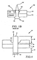
- the assembly 140 includes a deformed rivet 146, having a head 142 and a tail 154.
- the hole drilled into the first and second workpieces 114 and 115 includes a countersink 148 drilled into the second workpiece 115 to receive the head 142 of the deformed rivet 146.
- the fastened assembly 140 when produced by the LVEMR system 100 described above, has significant gaps 150 between the head 142 of the deformed rivet 146 and the countersink 148.
- the gaps 150 are undesirable since they could lead to early corrosion of the deformed rivet 146, causing it to weaken and prematurely fail. Accordingly, for the foregoing reasons, there is a need in the art for a controlled low-voltage electromagnetic riveting process that mitigates the gaps 150 between the rivet head 142 and the countersink 148.
- a riveter comprising two riveting guns each including a pair of coil means, one of which is drivingly associated with a forming tool or anvil.
- the use of a pair of coil means per riveting gun instantiates a complex contraption.
- the present invention provides a method for mitigating gaps between a deformed head of a slug rivet and a countersink according to claim 1.
- the present invention provides a method for controlled low-voltage electromagnetic riveting according to claim 9.
- the following process and apparatus assist in controlling and balancing the forces applied to a rivet. Such control mitigates gaps between a head of a rivet and a countersink into which it is deformed. Other advantages include more accurate control over rivet interferences and a reduction in reactive forces applied to an object being riveted.
- LVEMR Low voltage electromagnetic rivet
- the force-displacement relationship of a head 21 and tail 23 of a rivet 22 are manipulated via the forming characteristics of the rivet 22 to maintain a force balance between the head 21 and the tail 22.
- the third factor affecting the force-displacement relationship of the rivet 22 is the amount of rivet 22 that extends out of the primary sheet 24 and the secondary sheet 26. This includes a head protrusion 28 of the rivet 22 above a countersink 25 in the primary sheet 24 to be coupled to the secondary sheet 26, as shown in Fig. 4 .
- the third factor also includes a tail protrusion 30 from the secondary sheet 26. The larger the protrusion values for the head protrusion 28 and the tail protrusion 30, the more the displacement of the protrusion for a given force, i.e., a soft force-displacement relationship.
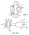
- the fourth factor affecting the force-displacement is the geometry of the countersink 25, and the fifth factor is the design of a head die 32 and a tail die 34 used to upset the rivet 22, as shown in Figs. 4 and 5 .
- Captivating dies, such as the tail die 34, and deep countersinks, such as the countersink 25, create a stiffer force-displacement relationship. Therefore, there is less displacement of the rivet 22 for a given force when using dies, such as the tail die 34, and countersinks, such as countersink 25, that prevent the material of the rivet 22 from flowing outward when it is upset.
- a preferred combination of the above-described factors maintains a balanced force, i.e. equal force on the tail 1 the head 23, throughout the riveting process which results in the elimination of any gaps between the deformed head and the countersink 25.
- the preferred combination has the amount of head protrusion 28 at a length that is five to ten percent less than the length of the tail protrusion 30.
- Head Protrusion 1 - .05 to .10
- the tail protrusion 30 is preferably .9 to 1.3 times a diameter 19 of the rivet 22.
- Tail Protrusion .9 to 1.3 Rivet Diameter .
- the depth 44 of a contact surface 36 of the tool die 34 in the preferred combination must be similar to, i.e. within 20% of, the depth 42 of the countersink 25.
- the contact surface 38 of the head die 32 is preferably flat.
- an upper diameter 40 of the tail die 34 must be similar to a countersink diameter 37, i.e. the upper diameter 40 must be within 20% of the countersink diameter 37.
- an upper angle or taper 48 ofthe edge of the die surface of the tail die 34 must be similar, i.e. to an upper angle or taper 46 of the countersink, i.e. within 20%.
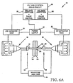
- the force applied to a head and a tail of a rivet is balanced, i.e. applied equally over time, by controlling the rivet upsetting process using a monitoring and application assembly 50, shown in Fig. 6A .
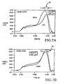
- the force applied to the head side is usually out of phase with and has a different magnitude than the force applied to the a tail side of the rivet 22, as shown in Fig. 7A .
- the assembly 50 can be used to create the proper differential voltage and timing so that the forces applied to the head and tail side of the rivet 22 are balanced, i.e., the forces applied over time to each side are nearly identical.
- the assembly 50 includes a first load-cell 56, and a second load-cell 58, used to monitor the force applied by the electromagnetic riveter during the riveting process.
- Each of the first and second load-cells 56 and 58 is mounted on respective first and second drivers 52 and 54, near its respective first and second rivet die 60 and 62.
- each of the first and second load-cells 56 and 58 is positioned no less than three inches from its respective first and second rivet die 60 and 62.
- the first load cell 56 and the second load cell 58 are identical and are described with reference to the first load cell 56, shown in Fig. 6B .
- the load cell 56 includes a piezo-electric quartz cell 66, preferably a PCB Model 204M device.
- An integral cable 68 extends from the quartz cell 66 and is coupled to a waveform analyzer 64, such as a Nicolet Module 2580, which digitally stores the electrical waveform produced by the quartz cell 66 when a force is applied to it.
- a waveform analyzer 64 such as a Nicolet Module 2580
- the quartz cell 66 is coupled to the driver 56 and the head die 60, so that it will receive and register at least 95% of the force applied by the driver 56, yet dampen external noise.
- Two pieces of tape 70a and 70b preferably Capton tape, are positioned on first and second sides of the quartz cell 66 that are orthogonal to a longitudinal axis of the driver 52. The two pieces of tape 70a and70b help dampen noise produced by the driver 56, which could interfere with an accurate measurement by the quartz cell 66.
- First and second respective steel washers 72a and 72b are respectively positioned adjacent the Capton tapes 70a and 70b.
- the first and second steel washers 72a and 72b, as well as the quartz cell 66, are annular, allowing a stud 74 to pass through.
- the stud 74 is preferably a copper beryllium threaded stud. Copper beryllium is preferred since it may be threaded to the driver 52 and the head die 60 coupling the two physically yet allowing 95% of the force from the driver 52 to pass through the load cell 56, instead of the stud 74.
- a portion 76 of the driver 52 may be threadingly detachable to allow easy maintenance and replacement of the load cell 58.
- the phase and magnitude of the force applied by the first and second drivers 52 and 54 are directly caused by a "charge dump" from a respective first and second capacitor bank 78 and 80 charged by a power cell 82 and controlled by a firing circuit 84.
- the firing circuit has a first phase and amplitude voltage control 86 for controlling the phase and magnitude of force, via voltage, of the first driver 52, and a second phase and amplitude control 88 for controlling the phase and magnitude of force, via voltage, of the second driver 54.
- the desired process conditions i.e. the desired rivet protrusion and die geometry
- the forces are then monitored by the first and second load cells 56 and 58 during the rivet-forming process with no differential voltage and no timing delay, yielding a force-over-time graph as shown in Fig. 7A .
- the force over time applied to the rivet 22 is recorded by the waveform analyzer 64.
- the timing delay is adjusted to bring the forces into phase.
- the forces are in phase when the peak forces are reached simultaneously, as shown in Fig. 7B . It is important to adjust phase first since amplitude often changes when the phase is changed. For example, in Fig. 7A , the head force has the greatest magnitude, while in Fig. 7B , the tail force has the greatest magnitude.
- the proper amount of delay is approximately equal to the difference in time between the head and tail peak forces. As shown in Figure 7A , if the phase difference 60 is 50 ⁇ s, where the head force precedes tail force, then the head force should be delayed about 50 ⁇ s by adjusting the phase using the first control 86.
- the voltages are adjusted to produce equal force magnitude, i.e. the greater force is reduced or the lesser force is increased by changing charge voltage via the firing circuit 84.
- the tail force needs to be decreased by adjusting voltage amplitude using the second control 88 until the tail force equals head force. It is most desirable if the entire force on the tail and head matches for their duration. However, if this match is not possible, it is important that the force peaks 61, i.e., the force having the greatest area, as shown in Fig. 7C , are as equal as possible. If the forces cannot be entirely aligned, then they must at least substantially match in this area.
Landscapes
- Engineering & Computer Science (AREA)
- Mechanical Engineering (AREA)
- Insertion Pins And Rivets (AREA)
- Connection Of Plates (AREA)
Claims (9)
- Verfahren zum Verringern von Zwischenräumen (150) zwischen einem deformierten Kopf (21) eines Niets (22) und einer Senkung (25) innerhalb eines ersten Werkstücks von zwei Werkstücken in einer Anordnung, welche von einer elektromagnetischen Niederspannungs-Nietvorrichtung (50), die einen kopfseitigen Aktuator (32) und einen endseitigen Aktuator (34) umfasst, gekoppelt wird, wobei das Verfahren folgende Schritte umfasst:- Auswählen eines Niets (22), welcher sich gleichförmig an einem Ende (23) und einem Kopf (21) des Niets deformiert, gekennzeichnet durch- Positionieren des Volumens des Niets in der Anordnung derart, dass vor einer Betätigung des kopfseitigen Aktuators und des endseitigen Aktuators das Ende des Niets aus einer Oberfläche eines zweiten Werkstücks der zwei Werkstücke um eine Länge des 0,9 - 1,3-fachen eines Durchmessers des Niets herausragt; und wobei der Kopf des Niets aus einer Basis der Senkung mit einer Länge herausragt, welche 5 % bis 10 % kleiner als die Länge des Endes des Niets ist, die aus der Oberfläche des zweiten Werkstücks herausragt, und dass eine über die Zeit auf den Kopf des Niets von dem kopfseitigen Aktuator angewendete Kraft gleich einer auf das Ende des Niets durch den endseitigen Aktuator angewendeten Kraft über die Zeit ist.
- Verfahren zum Verringern von Zwischenräumen nach Anspruch 1, wobei der Schritt des Positionierens des Volumens des Niets weiterhin folgenden Schritt umfasst:- Stauchen des Endes (23) des Niets mit einem mit dem endseitigen Aktuator gekoppelten Endstempel (34, 36), wobei der Endstempel eine Kontaktoberfläche mit einer Tiefe (44), einem Durchmesser und einer Abschrägung aufweist, welche im Wesentlichen gleich einer Tiefe, einem Durchmesser und einer Abschrägung der Senkung sind.
- Verfahren zum Verringern von Zwischenräumen gemäß Anspruch 2, wobei die Abmessungen des Stempels von den Abmessungen der Senkung um höchstens 20% abweichen.
- Verfahren nach Anspruch 2, wobei die Abmessungen des Stempels bevorzugt um höchstens 5% von den Abmessungen der Senkung abweichen.
- Verfahren nach einem der Ansprüche 2, 3 oder 4, umfassend:- Stauchen des Kopfes des Niets mit einem Kopfstempel, welcher eine flache Kontaktoberfläche aufweist, und- Stauchen des Endes des Niets mit dem Endstempel, wobei der Endstempel einen um höchstens 20% von der Tiefe der Senkung abweichenden oberen Durchmesser aufweist und wobei der Endstempel einen oberen Durchmesser innerhalb von 10 Grad des oberen Winkels der Senkung aufweist.
- Verfahren nach einem der vorhergehenden Ansprüche, wobei die elektromagnetische Niederspannungs-Nietvorrichtung (50) einen kopfseitigen Treiber (52) mit einer ersten Lastzelle (56), und einen endseitigen Treiber (54) mit einer zweiten Lastzelle (58) und eine Abschusssteuerschaltung (84, 86, 88), welche in der Lage ist, Phase und Größe einer Kraft zu steuern, welche durch den kopfseitigen Treiber und den endseitigen Treiber angewendet wird, aufweist,
wobei das Verfahren folgende Schritte umfasst:(a) Positionieren eines ersten Testniets in der Anordnung,(b) Überwachen einer ersten Ausgabe der ersten Lastzelle und der zweiten Lastzelle, während der erste Testniet gestaucht wird, um die Phase und die Größe der auf einen Kopf bzw. ein Ende des Niets von dem kopfseitigen Treiber bzw. dem endseitigen Treiber angewendeten Kraft zu bestimmen,(c) Vergleichen der ersten Ausgabe der ersten Lastzelle und der zweiten Lastzelle, welche auftrat, als der erste Testniet gestaucht wurde,(d) Anpassen entweder der durch den Kopftreiber angewendeten Kraft oder der durch den Endtreiber angewendeten Kraft derart, dass die Phase der von dem Kopftreiber angewendeten Kraft mit der Phase der durch den Endtreiber angewendeten Kraft übereinstimmt,(e) Positionieren eines zweiten Testniets in der Anordnung,(f) Überwachen einer zweiten Ausgabe der ersten Lastzelle und der zweiten Lastzelle, während der zweite Testniet gestaucht wird, um die Phase und die Größe der auf den Kopf bzw. das Ende des zweiten Testniets durch den kopfseitigen Treiber bzw. den endseitigen Treiber angewendeten Kraft zu bestimmen,(g) Vergleichen der zweiten Ausgabe der ersten Lastzelle und der zweiten Lastzelle, welche auftrat, als der zweite Testniet gestaucht wurde, und(h) Anpassen der Größe entweder der durch den Kopftreiber angewendeten Kraft oder der durch den Endtreiber angewendeten Kraft derart, dass die Größe der durch den Endtreiber angewendeten Kraft gleich der Größe der durch den Kopftreiber angewendeten Kraft ist. - Verfahren nach Anspruch 6, weiterhin umfassend den Schritt des Wiederholens der Schritte (a) bis (h), bis der erste und zweite Treiber über die Zeit eine Phase und eine Größe haben, welche im Wesentlichen gleich sind.
- Verfahren nach Anspruch 6, weiterhin umfassend die Schritte des Wiederholens der Schritte (a) bis (h) bis zumindest in einem Spitzenbereich der Kraft über die Zeit der erste und der zweite Treiber eine Phase und eine Größe aufweisen, welche im Wesentlichen gleich sind.
- Verfahren zum gesteuerten elektromagnetischen Niederspannungs-Nieten eines Niets in zwei Werkstücken, wobei ein erstes der zwei Werkstücke eine Senkung umfasst, wobei das Verfahren folgende Schritte umfasst:- Positionieren eines Niets innerhalb der zwei Werkstücke, so dass ein Ende des Niets aus einer Oberfläche eines zweiten Werkstücks der zwei Werkstücke um eine Länge des 0,9 - 1,3-fachen eines Durchmessers des Niets herausragt; und wobei der Kopf des Niets aus einer Basis der Senkung mit einer Länge herausragt, welche 5 % bis 10 % kleiner als die Länge des Endes des Niets ist, die aus der Oberfläche des zweiten Werkstücks herausragt;- Überwachen der während einer Deformation des Niets durch das elektromagnetische Niederspannungs-Nieten auf einen Kopf und ein Ende eines Niets angewendeten Kraft über die Zeit,- Anpassen einer Phase der auf zumindest einen Ort des Kopfes und des Endes des Niets angewendeten Kraft, so dass die Phase der auf den Ort des Kopfes des Niets angewendeten Kraft gleich der Phase der auf den Ort des Endes des Niets angewendeten Kraft ist, und- Anpassen einer Größe der auf den Ort des Nietenkopfes und des Endes des Niets angewendeten Kraft, so dass die Größe der auf den Nietenkopf angewendeten Kraft gleich der auf den Ort des Endes des Niets angewendeten Kraft ist.
Applications Claiming Priority (2)
| Application Number | Priority Date | Filing Date | Title |
|---|---|---|---|
| US09/096,884 US6014804A (en) | 1998-06-12 | 1998-06-12 | Low voltage electromagnetic process and apparatus for controlled riveting |
| US96884 | 1998-06-12 |
Publications (4)
| Publication Number | Publication Date |
|---|---|
| EP0963803A2 EP0963803A2 (de) | 1999-12-15 |
| EP0963803A3 EP0963803A3 (de) | 2000-11-22 |
| EP0963803B1 EP0963803B1 (de) | 2004-08-25 |
| EP0963803B2 true EP0963803B2 (de) | 2009-08-26 |
Family
ID=22259560
Family Applications (1)
| Application Number | Title | Priority Date | Filing Date |
|---|---|---|---|
| EP99201897A Expired - Lifetime EP0963803B2 (de) | 1998-06-12 | 1999-06-14 | Nierdespannungs-Elektromagnetische Nietverfahren zum gesteuerten Nieten |
Country Status (5)
| Country | Link |
|---|---|
| US (3) | US6014804A (de) |
| EP (1) | EP0963803B2 (de) |
| CA (1) | CA2272663C (de) |
| DE (1) | DE69919626T3 (de) |
| ES (1) | ES2222660T5 (de) |
Cited By (1)
| Publication number | Priority date | Publication date | Assignee | Title |
|---|---|---|---|---|
| DE102013206547A1 (de) | 2013-04-12 | 2014-10-16 | Airbus Operations Gmbh | Nietvorrichtung und Nietverfahren |
Families Citing this family (16)
| Publication number | Priority date | Publication date | Assignee | Title |
|---|---|---|---|---|
| US9015920B2 (en) | 1997-07-21 | 2015-04-28 | Newfrey Llc | Riveting system and process for forming a riveted joint |
| US6276050B1 (en) * | 1998-07-20 | 2001-08-21 | Emhart Inc. | Riveting system and process for forming a riveted joint |
| US6789309B2 (en) | 2000-02-22 | 2004-09-14 | Newfrey Llc | Self-piercing robotic rivet setting system |
| DE50109817D1 (de) * | 2001-07-19 | 2006-06-22 | Hilti Ag | Bolzensetzgerät mit Setztiefenregelung |
| CA2471676A1 (en) * | 2001-12-27 | 2003-07-31 | Newfrey Llc. | Automatic punching riveting device and die used for the device |
| GB2390833B (en) * | 2002-07-18 | 2005-09-14 | Emhart Llc | Method and apparatus for monitoring blind fastener setting |
| US6823709B2 (en) * | 2002-08-06 | 2004-11-30 | The Boeing Company | Synchronized rivet gun system |
| DE10332474A1 (de) * | 2003-07-16 | 2005-02-24 | Baltec Maschinenbau AG, Pfäffikon | Verfahren zum Verbinden von Bauteilen mittels Nieten |
| DE102004005859A1 (de) * | 2004-02-05 | 2005-08-25 | Claas Fertigungstechnik Gmbh | Vorrichtung zur Fixierung von Nietelementen in Bauteilen |
| EP1750868A1 (de) * | 2004-03-24 | 2007-02-14 | Newfrey LLC | Nietüberwachungssystem |
| US7802352B2 (en) * | 2005-04-13 | 2010-09-28 | Newfrey Llc | Monitoring system for fastener setting tool |
| US20100000011A1 (en) * | 2008-07-03 | 2010-01-07 | Rodrigo Angarita | Plumbing apparatus adapted with removable filtering container |
| US9027220B2 (en) | 2012-08-07 | 2015-05-12 | Newfrey Llc | Rivet setting machine |
| DE102015014517B3 (de) * | 2014-02-03 | 2017-05-18 | Kiefel Gmbh | Verfahren zum Nieten, Nietanlage und Airbagbauteil |
| CN109262226B (zh) * | 2018-11-17 | 2023-10-31 | 广东钺河智能科技有限公司 | 一种新型散端铆碳片自动组装机 |
| CN115971395A (zh) * | 2023-02-13 | 2023-04-18 | 凌云科技集团有限责任公司 | 一种铆接尺寸控制方法及铆接尺寸控制装置 |
Citations (2)
| Publication number | Priority date | Publication date | Assignee | Title |
|---|---|---|---|---|
| US4864713A (en) † | 1988-06-07 | 1989-09-12 | Gemcor Engineering Corp. | Method and apparatus for positioning tooling and riveting |
| US5752306A (en) † | 1990-12-21 | 1998-05-19 | The Boeing Company | Method for upsetting a headed rivet by differential initiation of opposed electromagnetic rivet drivers |
Family Cites Families (17)
| Publication number | Priority date | Publication date | Assignee | Title |
|---|---|---|---|---|
| US3747382A (en) * | 1967-10-19 | 1973-07-24 | Univ Ohio State | Metal working apparatus and process |
| US3557442A (en) * | 1968-04-02 | 1971-01-26 | Gen Electro Mech Corp | Slug riveting method and apparatus |
| US3634928A (en) * | 1968-09-09 | 1972-01-18 | Boeing Co | Method of rivet joining |
| US3874070A (en) * | 1973-08-03 | 1975-04-01 | Boeing Co | High fatigue squeeze riveting process and apparatus therefor |
| US4027539A (en) * | 1976-04-09 | 1977-06-07 | Halloran John D | Apparatus for, and method of, measuring dynamic forces |
| US4858289A (en) * | 1983-05-06 | 1989-08-22 | Gemcor Engineering Corp. | Dimpling and riveting apparatus |
| US4862043A (en) * | 1987-05-27 | 1989-08-29 | Zieve Peter B | Low voltage electromagnetic pulse actuator |
| US4984347A (en) * | 1989-05-05 | 1991-01-15 | Mcdonnell Douglas Corporation | Method for attaching a doubler to a skin structure |
| US5273386A (en) * | 1990-03-23 | 1993-12-28 | Allfast Fastening Systems, Inc. | Expandable head rivet |
| US5060362A (en) * | 1990-07-10 | 1991-10-29 | Gemcor Engineering Corp. | Slug riveting method and apparatus with C-frame deflection compensation |
| US5222289A (en) * | 1990-07-10 | 1993-06-29 | Gemcor Engineering Corp. | Method and apparatus for fastening |
| NL9100286A (nl) * | 1991-02-19 | 1992-09-16 | Michiel Pieter Brandts | Werkwijze, snapper, nagel, etc. voor het met elkaar verbinden van een platenpakket d.m.v. klinknagels uit een al-legering. |
| US5398537A (en) * | 1991-12-06 | 1995-03-21 | Gemcor Engineering Corporation | Low amperage electromagnetic apparatus and method for uniform rivet upset |
| US5471865A (en) * | 1993-09-09 | 1995-12-05 | Gemcor Engineering Corp. | High energy impact riveting apparatus and method |
| CA2116934C (en) * | 1994-03-03 | 2000-08-01 | Murray R. Harman | Method for controlling the contact of optical fibers |
| US5509317A (en) * | 1994-10-07 | 1996-04-23 | Illinois Tool Works, Inc. | Load cell mounting |
| US5813110A (en) * | 1996-02-09 | 1998-09-29 | The Boeing Company | Low-voltage eletromagnetic riveter |
-
1998
- 1998-06-12 US US09/096,884 patent/US6014804A/en not_active Expired - Lifetime
-
1999
- 1999-05-21 CA CA002272663A patent/CA2272663C/en not_active Expired - Lifetime
- 1999-06-14 DE DE69919626T patent/DE69919626T3/de not_active Expired - Lifetime
- 1999-06-14 EP EP99201897A patent/EP0963803B2/de not_active Expired - Lifetime
- 1999-06-14 ES ES99201897T patent/ES2222660T5/es not_active Expired - Lifetime
- 1999-11-15 US US09/439,757 patent/US6176000B1/en not_active Expired - Fee Related
-
2000
- 2000-09-22 US US09/667,491 patent/US6446319B1/en not_active Expired - Fee Related
Patent Citations (2)
| Publication number | Priority date | Publication date | Assignee | Title |
|---|---|---|---|---|
| US4864713A (en) † | 1988-06-07 | 1989-09-12 | Gemcor Engineering Corp. | Method and apparatus for positioning tooling and riveting |
| US5752306A (en) † | 1990-12-21 | 1998-05-19 | The Boeing Company | Method for upsetting a headed rivet by differential initiation of opposed electromagnetic rivet drivers |
Cited By (1)
| Publication number | Priority date | Publication date | Assignee | Title |
|---|---|---|---|---|
| DE102013206547A1 (de) | 2013-04-12 | 2014-10-16 | Airbus Operations Gmbh | Nietvorrichtung und Nietverfahren |
Also Published As
| Publication number | Publication date |
|---|---|
| CA2272663A1 (en) | 1999-12-12 |
| ES2222660T3 (es) | 2005-02-01 |
| EP0963803A3 (de) | 2000-11-22 |
| EP0963803A2 (de) | 1999-12-15 |
| US6176000B1 (en) | 2001-01-23 |
| DE69919626T3 (de) | 2010-01-21 |
| ES2222660T5 (es) | 2010-01-29 |
| US6014804A (en) | 2000-01-18 |
| EP0963803B1 (de) | 2004-08-25 |
| DE69919626T2 (de) | 2005-02-03 |
| US6446319B1 (en) | 2002-09-10 |
| CA2272663C (en) | 2007-07-24 |
| DE69919626D1 (de) | 2004-09-30 |
Similar Documents
| Publication | Publication Date | Title |
|---|---|---|
| EP0963803B2 (de) | Nierdespannungs-Elektromagnetische Nietverfahren zum gesteuerten Nieten | |
| US5398537A (en) | Low amperage electromagnetic apparatus and method for uniform rivet upset | |
| DE69712381T2 (de) | Niederspannungs-Elektromagnetisches Nietwerkzeug | |
| US7131310B2 (en) | Method for manufacturing improved fatigue life structures, and structures made via the method | |
| EP2612717B1 (de) | Nietwerkzeug und Verfahren mit elektromagnetischer Normalisierung der Matrize | |
| US20150101175A1 (en) | Automated percussive riveting system | |
| US4815193A (en) | Rivet installation tool and method of installing rivets | |
| US4129028A (en) | Method and apparatus for working a hole | |
| IL138508A (en) | Method and apparatus for producing beneficial stresses around apertures by the use of of focused stress waves | |
| US6230537B1 (en) | Method and apparatus for producing beneficial stresses around apertures by use of focused stress waves, and improved fatigue life products made by the method | |
| DE102013000387B4 (de) | Fügevorrichtung mit C-förmigen Rahmen und nachgiebiger Matrize zum vorlochfreien Fügen von Bauteilen mittels kraftimpulsbeaufschlagtem Fügeelement, sowie Matrizenhalter und Handhabungsvorrichtung hierfür | |
| DE102009051571A1 (de) | Fügeverfahren und Fügevorrichtung | |
| Hartmann et al. | Low voltage electromagnetic lockbolt installation | |
| DE102017215099A1 (de) | Stanzniet für eine stanznietvorrichtung zum setzen eines stanzniets mit einer eine stempelkraft unterstützenden schwingung | |
| Gao et al. | Intelligent Robotic Electromagnetic Riveting Interference Connection Technology for Aircraft Assembly | |
| Wallace | Electromagnetic Bolt Inserter | |
| RU2071910C1 (ru) | Способ обработки заготовок давлением и ударное устройство с электромагнитным приводом для его осуществления | |
| RU2138359C1 (ru) | Способ выполнения высокоресурсных соединений стержневыми заклепками | |
| Giddings | Aircraft riveting | |
| Leftheris | Stress wave riveting |
Legal Events
| Date | Code | Title | Description |
|---|---|---|---|
| PUAI | Public reference made under article 153(3) epc to a published international application that has entered the european phase |
Free format text: ORIGINAL CODE: 0009012 |
|
| AK | Designated contracting states |
Kind code of ref document: A2 Designated state(s): DE ES FR GB |
|
| AX | Request for extension of the european patent |
Free format text: AL;LT;LV;MK;RO;SI |
|
| PUAL | Search report despatched |
Free format text: ORIGINAL CODE: 0009013 |
|
| AK | Designated contracting states |
Kind code of ref document: A3 Designated state(s): AT BE CH CY DE DK ES FI FR GB GR IE IT LI LU MC NL PT SE |
|
| AX | Request for extension of the european patent |
Free format text: AL;LT;LV;MK;RO;SI |
|
| 17P | Request for examination filed |
Effective date: 20010417 |
|
| AKX | Designation fees paid |
Free format text: DE ES FR GB |
|
| 17Q | First examination report despatched |
Effective date: 20020724 |
|
| GRAP | Despatch of communication of intention to grant a patent |
Free format text: ORIGINAL CODE: EPIDOSNIGR1 |
|
| GRAS | Grant fee paid |
Free format text: ORIGINAL CODE: EPIDOSNIGR3 |
|
| GRAA | (expected) grant |
Free format text: ORIGINAL CODE: 0009210 |
|
| AK | Designated contracting states |
Kind code of ref document: B1 Designated state(s): DE ES FR GB |
|
| REG | Reference to a national code |
Ref country code: GB Ref legal event code: FG4D |
|
| REF | Corresponds to: |
Ref document number: 69919626 Country of ref document: DE Date of ref document: 20040930 Kind code of ref document: P |
|
| REG | Reference to a national code |
Ref country code: ES Ref legal event code: FG2A Ref document number: 2222660 Country of ref document: ES Kind code of ref document: T3 |
|
| PLAQ | Examination of admissibility of opposition: information related to despatch of communication + time limit deleted |
Free format text: ORIGINAL CODE: EPIDOSDOPE2 |
|
| PLAR | Examination of admissibility of opposition: information related to receipt of reply deleted |
Free format text: ORIGINAL CODE: EPIDOSDOPE4 |
|
| PLBQ | Unpublished change to opponent data |
Free format text: ORIGINAL CODE: EPIDOS OPPO |
|
| PLBI | Opposition filed |
Free format text: ORIGINAL CODE: 0009260 |
|
| PLAQ | Examination of admissibility of opposition: information related to despatch of communication + time limit deleted |
Free format text: ORIGINAL CODE: EPIDOSDOPE2 |
|
| PLAR | Examination of admissibility of opposition: information related to receipt of reply deleted |
Free format text: ORIGINAL CODE: EPIDOSDOPE4 |
|
| PLBQ | Unpublished change to opponent data |
Free format text: ORIGINAL CODE: EPIDOS OPPO |
|
| PLAB | Opposition data, opponent's data or that of the opponent's representative modified |
Free format text: ORIGINAL CODE: 0009299OPPO |
|
| PLAX | Notice of opposition and request to file observation + time limit sent |
Free format text: ORIGINAL CODE: EPIDOSNOBS2 |
|
| ET | Fr: translation filed | ||
| 26 | Opposition filed |
Opponent name: AIRBUS SAS/AIRBUS FRANCE/AIRBUS UK LIMITED/AIRBUS Effective date: 20050523 |
|
| R26 | Opposition filed (corrected) |
Opponent name: AIRBUS SAS/AIRBUS FRANCE/AIRBUS UK LIMITED/AIRBUS Effective date: 20050523 |
|
| PLAF | Information modified related to communication of a notice of opposition and request to file observations + time limit |
Free format text: ORIGINAL CODE: EPIDOSCOBS2 |
|
| PLAF | Information modified related to communication of a notice of opposition and request to file observations + time limit |
Free format text: ORIGINAL CODE: EPIDOSCOBS2 |
|
| PLBB | Reply of patent proprietor to notice(s) of opposition received |
Free format text: ORIGINAL CODE: EPIDOSNOBS3 |
|
| RIC2 | Information provided on ipc code assigned after grant |
Ipc: B21J 15/28 20060101ALI20090407BHEP Ipc: B21J 15/24 20060101AFI20090407BHEP |
|
| RTI2 | Title (correction) |
Free format text: LOW VOLTAGE ELECTROMAGNETIC CONTROLLED RIVETING PROCESS |
|
| PUAH | Patent maintained in amended form |
Free format text: ORIGINAL CODE: 0009272 |
|
| STAA | Information on the status of an ep patent application or granted ep patent |
Free format text: STATUS: PATENT MAINTAINED AS AMENDED |
|
| 27A | Patent maintained in amended form |
Effective date: 20090826 |
|
| AK | Designated contracting states |
Kind code of ref document: B2 Designated state(s): DE ES FR GB |
|
| REG | Reference to a national code |
Ref country code: ES Ref legal event code: DC2A Date of ref document: 20091119 Kind code of ref document: T5 |
|
| REG | Reference to a national code |
Ref country code: FR Ref legal event code: PLFP Year of fee payment: 18 |
|
| REG | Reference to a national code |
Ref country code: FR Ref legal event code: PLFP Year of fee payment: 19 |
|
| REG | Reference to a national code |
Ref country code: FR Ref legal event code: PLFP Year of fee payment: 20 |
|
| PGFP | Annual fee paid to national office [announced via postgrant information from national office to epo] |
Ref country code: FR Payment date: 20180626 Year of fee payment: 20 |
|
| PGFP | Annual fee paid to national office [announced via postgrant information from national office to epo] |
Ref country code: DE Payment date: 20180627 Year of fee payment: 20 Ref country code: ES Payment date: 20180702 Year of fee payment: 20 Ref country code: GB Payment date: 20180627 Year of fee payment: 20 |
|
| REG | Reference to a national code |
Ref country code: DE Ref legal event code: R071 Ref document number: 69919626 Country of ref document: DE |
|
| REG | Reference to a national code |
Ref country code: GB Ref legal event code: PE20 Expiry date: 20190613 |
|
| PG25 | Lapsed in a contracting state [announced via postgrant information from national office to epo] |
Ref country code: GB Free format text: LAPSE BECAUSE OF EXPIRATION OF PROTECTION Effective date: 20190613 |
|
| REG | Reference to a national code |
Ref country code: ES Ref legal event code: FD2A Effective date: 20200723 |
|
| PG25 | Lapsed in a contracting state [announced via postgrant information from national office to epo] |
Ref country code: ES Free format text: LAPSE BECAUSE OF EXPIRATION OF PROTECTION Effective date: 20190615 |