EP0964123B1 - Hängeschloss mit auswechselbarem schlüsselbetätigtem Zylinderkern - Google Patents
Hängeschloss mit auswechselbarem schlüsselbetätigtem Zylinderkern Download PDFInfo
- Publication number
- EP0964123B1 EP0964123B1 EP98304670A EP98304670A EP0964123B1 EP 0964123 B1 EP0964123 B1 EP 0964123B1 EP 98304670 A EP98304670 A EP 98304670A EP 98304670 A EP98304670 A EP 98304670A EP 0964123 B1 EP0964123 B1 EP 0964123B1
- Authority
- EP
- European Patent Office
- Prior art keywords
- shackle
- lock
- plunger
- catch
- receiving space
- Prior art date
- Legal status (The legal status is an assumption and is not a legal conclusion. Google has not performed a legal analysis and makes no representation as to the accuracy of the status listed.)
- Expired - Lifetime
Links
- 230000000717 retained effect Effects 0.000 claims abstract description 5
- 230000000694 effects Effects 0.000 description 4
- 230000006835 compression Effects 0.000 description 3
- 238000007906 compression Methods 0.000 description 3
- 230000005484 gravity Effects 0.000 description 2
- 238000000926 separation method Methods 0.000 description 2
- 238000003466 welding Methods 0.000 description 2
- 230000006378 damage Effects 0.000 description 1
- 230000002093 peripheral effect Effects 0.000 description 1
Images

Classifications
-
- E—FIXED CONSTRUCTIONS
- E05—LOCKS; KEYS; WINDOW OR DOOR FITTINGS; SAFES
- E05B—LOCKS; ACCESSORIES THEREFOR; HANDCUFFS
- E05B9/00—Lock casings or latch-mechanism casings ; Fastening locks or fasteners or parts thereof to the wing
- E05B9/08—Fastening locks or fasteners or parts thereof, e.g. the casings of latch-bolt locks or cylinder locks to the wing
- E05B9/084—Fastening of lock cylinders, plugs or cores
-
- E—FIXED CONSTRUCTIONS
- E05—LOCKS; KEYS; WINDOW OR DOOR FITTINGS; SAFES
- E05B—LOCKS; ACCESSORIES THEREFOR; HANDCUFFS
- E05B67/00—Padlocks; Details thereof
- E05B67/06—Shackles; Arrangement of the shackle
- E05B67/22—Padlocks with sliding shackles, with or without rotary or pivotal movement
- E05B67/24—Padlocks with sliding shackles, with or without rotary or pivotal movement with built- in cylinder locks
-
- E—FIXED CONSTRUCTIONS
- E05—LOCKS; KEYS; WINDOW OR DOOR FITTINGS; SAFES
- E05B—LOCKS; ACCESSORIES THEREFOR; HANDCUFFS
- E05B67/00—Padlocks; Details thereof
- E05B67/38—Auxiliary or protective devices
-
- Y—GENERAL TAGGING OF NEW TECHNOLOGICAL DEVELOPMENTS; GENERAL TAGGING OF CROSS-SECTIONAL TECHNOLOGIES SPANNING OVER SEVERAL SECTIONS OF THE IPC; TECHNICAL SUBJECTS COVERED BY FORMER USPC CROSS-REFERENCE ART COLLECTIONS [XRACs] AND DIGESTS
- Y10—TECHNICAL SUBJECTS COVERED BY FORMER USPC
- Y10T—TECHNICAL SUBJECTS COVERED BY FORMER US CLASSIFICATION
- Y10T70/00—Locks
- Y10T70/40—Portable
- Y10T70/413—Padlocks
- Y10T70/437—Key-controlled
- Y10T70/446—Rigid shackle
- Y10T70/452—Sliding
- Y10T70/459—Both legs engaged
-
- Y—GENERAL TAGGING OF NEW TECHNOLOGICAL DEVELOPMENTS; GENERAL TAGGING OF CROSS-SECTIONAL TECHNOLOGIES SPANNING OVER SEVERAL SECTIONS OF THE IPC; TECHNICAL SUBJECTS COVERED BY FORMER USPC CROSS-REFERENCE ART COLLECTIONS [XRACs] AND DIGESTS
- Y10—TECHNICAL SUBJECTS COVERED BY FORMER USPC
- Y10T—TECHNICAL SUBJECTS COVERED BY FORMER US CLASSIFICATION
- Y10T70/00—Locks
- Y10T70/40—Portable
- Y10T70/413—Padlocks
- Y10T70/487—Parts, accessories, attachments and adjuncts
- Y10T70/491—Shackles
-
- Y—GENERAL TAGGING OF NEW TECHNOLOGICAL DEVELOPMENTS; GENERAL TAGGING OF CROSS-SECTIONAL TECHNOLOGIES SPANNING OVER SEVERAL SECTIONS OF THE IPC; TECHNICAL SUBJECTS COVERED BY FORMER USPC CROSS-REFERENCE ART COLLECTIONS [XRACs] AND DIGESTS
- Y10—TECHNICAL SUBJECTS COVERED BY FORMER USPC
- Y10T—TECHNICAL SUBJECTS COVERED BY FORMER US CLASSIFICATION
- Y10T70/00—Locks
- Y10T70/40—Portable
- Y10T70/413—Padlocks
- Y10T70/487—Parts, accessories, attachments and adjuncts
- Y10T70/493—Protectors
- Y10T70/498—Shields or canopies
-
- Y—GENERAL TAGGING OF NEW TECHNOLOGICAL DEVELOPMENTS; GENERAL TAGGING OF CROSS-SECTIONAL TECHNOLOGIES SPANNING OVER SEVERAL SECTIONS OF THE IPC; TECHNICAL SUBJECTS COVERED BY FORMER USPC CROSS-REFERENCE ART COLLECTIONS [XRACs] AND DIGESTS
- Y10—TECHNICAL SUBJECTS COVERED BY FORMER USPC
- Y10T—TECHNICAL SUBJECTS COVERED BY FORMER US CLASSIFICATION
- Y10T70/00—Locks
- Y10T70/70—Operating mechanism
- Y10T70/7441—Key
- Y10T70/7486—Single key
- Y10T70/7508—Tumbler type
- Y10T70/7559—Cylinder type
- Y10T70/7661—Detachable or removable cylinder
Definitions
- the present invention relates to a padlock, more particularly to a padlock which has a replaceable key-operated lock core and which can provide an enhanced anti-theft effect.
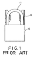
- Figure 1 illustrates a conventional padlock which includes a lock base 10, a shackle 11 with longer and shorter leg portions, and a pair of shackle guards 12.
- the conventional padlock suffers from the following drawbacks: A lock unit is mounted securely and is disposed within the lock base 10 so as to protect the same from destruction by a thief. However, in case the lock unit has corroded or is damaged such that it cannot be operated by the corresponding key, or in case ways of disabling the lock unit are known to a thief, the padlock will be ineffective. Since the lock unit is mounted securely within the lock base 10, replacement of the lock unit is impossible. Added expenses arise in view of the need to replace the entire padlock.
- the shackle guards 12 enclose the longer and shorter leg portions of the shackle 11 to protect the shackle 11 from being sawn or damaged undesirably while the padlock is in a locking state.
- the shackle guards 12 might be removed undesirably from the lock base 10 and might be misplaced. The conventional padlock is thus not satisfactory and has a poor anti-theft effect.
- the object of the present invention is to provide a padlock which has a replaceable key-operated lock core and an enhanced anti-theft effect to overcome the drawbacks that are associated with the aforementioned prior art.
- US3,254,516 discloses a padlock in which the lock cylinder can be removed for replacement using a special tool inserted through one of the shackle holes in the lock body.
- a padlock comprising:
- the retaining means is disposed in an innermost end of the second shackle insert hole and extends radially into the lock receiving space.
- the lock base has upper and lower ends.
- the first and second shackle insert holes extend from the upper end toward the lower end.
- the lock receiving space extends from the lower end toward the upper end and is disposed between the shackle insert holes.
- the lock receiving space has an upper section formed as a catch chamber which extends between the shackle insert holes.
- the lock unit includes an axially rotatable key-operated lock core which is provided with a plunger that is disposed in the catch chamber.
- the padlock further includes catch means disposed in the catch chamber.
- the catch means includes first and second catch units on opposite sides of the plunger, and spring means for pulling together the first and second catch units so as to engage the plunger.
- the lock core is rotatable so as to rotate the plunger between a locking position, where the plunger forces apart the first and second catch units against action of the spring means so as to extend the first and second catch units into the shackle insert holes in order to engage the longer and shorter leg portions of the shackle, and an unlocking position, where the plunger ceases to force apart the first and second catch units so as to retract the first and second catch units into the catch chamber by virtue of the spring means in order to permit removal of the shorter leg portion of the shackle from the second shackle insert hole.
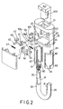
- the padlock according to the first preferred embodiment of this invention is shown to include a lock base 20, a lock unit 100, a shackle 30, first and second catch members 40, 50, first and second biasing springs 45, 55, and a pair of elongated shackle guards 60.
- the lock base 20 has upper and lower ends, substantially parallel first and second shackle insert holes 22, 25 extending from the upper end toward the lower end, and a lock receiving space 21 extending from the lower end toward the upper end.
- the lock receiving space 21 is disposed between and is generally parallel to the first and second shackle insert holes 22, 25.
- the lock receiving space 21 has an upper section formed as a catch chamber 210 which extends between the shackle insert holes 22, 25.
- the upper end of the lock base 20 has two opposite notches 24 which are formed respectively in lateral walls of the lock base 20 and which extend to a respective one of the shackle insert holes 22, 25.
- the lock unit 100 is received in the lock receiving space 21 and includes an axially rotatable key-operated lock core 105 which is provided with a plunger 101.
- the plunger 101 is disposed in the catch chamber 210 and has a wider upper section 101a and a narrower lower section 101b.
- the shackle 30 has a spring-loaded longer leg portion 32 which is retained slidably and rotatably in the first shackle insert hole 22 in a known manner, and a shorter leg portion 35 which is received removably in the second shackle insert hole 25.
- Each of the longer and shorter leg portions 32, 35 is formed with a locking notch 31 at an inner side thereof.
- the first and second catch members 40, 50 are disposed side-by-side in the catch chamber 210 and are slidable relative to one another.
- Each of the catch members 40, 50 has an outer end formed with a shackle engaging portion 42, 52 for engaging the locking notch 31 in a respective one of the longer and shorter leg portions 32, 35 of the shackle 30, and an inner end formed with a plunger engaging portion 41, 51 for engaging the plunger 101 of the lock core 105.
- the plunger engaging portion 41 of the first catch member 40 extends between the plunger engaging portion 51 and the shackle engaging portion 52 of the second catch member 50.
- each of the catch members 40, 50 is further formed with a pair of pawl projections 43, 53.
- each of the pawl projections 43, 53 has an inclined face which inclines downwardly in a direction toward the inner end of the respective catch member 40, 50.
- the first biasing spring 45 is disposed between the shackle engaging portion 42 of the first catch member 40 and the plunger engaging portion 51 of the second catch member 50.
- the second biasing spring 55 is disposed between the shackle engaging portion 52 of the second catch member 50 and the plunger engaging portion 41 of the first catch member 40.
- the first and second biasing springs 45, 55 constitute spring means for biasing the shackle engaging portions 42, 52 outward to extend respectively and resiliently into the shackle insert holes 22, 25, and for biasing the plunger engaging portions 41, 51 inward to engage respectively opposite sides of the plunger 101 for retaining the lock unit 100 in the lock receiving space 21.
- the spring means i.e, the first and second biasing springs 45, 55, and the first and second catch members 40, 50 serve as retaining means for engaging the plunger 101 so as to retain releasably the lock unit 100 in the lock receiving space 21.
- each of the shackle guards 60 has a generally U-shaped cross-section with two opposite longitudinal edges formed with ratchet teeth 61 therealong for engaging the pawl projections 43, 53 of the catch members 40, 50.
- Each of the longitudinal edges of the shackle guards 60 has a U-shaped retaining groove 611 adjacent to a lowermost one of the ratchet teeth 61.
- Each of the shackle guards 60 is further formed with an outwardly protruding push projection 62 at an upper end thereof to permit pushing of the shackle guards 60 upwardly for extension out of the shackle insert holes 22, 25.
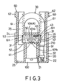
- the lock core 105 of the lock unit 100 is rotatable when operated by the correct key (not shown) so as to rotate the plunger 101 between a locking position as shown in Figure 3, and an unlocking position as shown in Figure 4.
- the wider upper section 101a of the plunger 101 forces apart the first and second catch members 40, 50 to prevent retraction of the shackle engaging portions 42, 52 into the catch chamber 210 so as to prevent removal of the shorter leg portion 35 from the second shackle insert hole 25.
- the pawl projections 43, 53 of the first and second catch members 40, 50 extend respectively into the shackle insert holes 22, 25 to engage the ratchet teeth 61 on the shackle guards 60 so that the shackle guards 60 can be prevented from moving downwardly and retracting into the shackle insert holes 22, 25 and so that the shackle guards 60 can be moved upwardly by pushing the push projections 62 in order to enclose respectively outer sides of the longer and shorter leg portions 32, 35 of the shackle 30.
- the retaining grooves 611 formed on the shackle guards 60 limit extension of the shackle guards 60 so as to prevent separation of the shackle guards 60 from the lock base 20 during upward movement of the shackle guards 60.
- the plunger 101 when the plunger 101 is in the unlocking position, the plunger 101 permits retraction of the shackle engaging portions 42, 52 of the first and second catch members 40, 50 into the catch chamber 210 to permit upward movement of the longer leg portion 32 in the first shackle insert hole 22 and removal of the shorter leg portion 35 from the second shackle insert hole 25.
- the pawl projections 43, 53 on the catch members 40, 50 are retracted into the catch chamber 210 to disengage the ratchet teeth 61 on the shackle guards 60 so as to permit retraction of the shackle guards 60 into the shackle insert holes 22, 25 by virtue of gravity in order to expose the longer and shorter leg portions 32, 35 of the shackle 30.
- the push projections 62 are received fittingly and respectively in the notches 24.
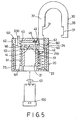
- the lock unit 100 When the lock unit 100 has corroded, is damaged, or when the lock unit 100 does not work for some reason, it can be removed from the lock receiving space 21 of the lock base 20 for replacement with a new one. Removal of the lock unit 100 is conducted in the following manner, with reference to Figure 5: After the shorter leg portion 35 of the shackle 30 has been removed from the second shackle insert hole 25 of the lock base 20, the longer leg portion 32 is rotated axially in the first shackle insert hole 22 to expose an upper section of the second shackle insert hole 25.
- a tool 200 is extended into the catch chamber 210 via the second shackle insert hole 25 to force the second catch member 50 to retract into the catch chamber 210 and to force the plunger engaging portions 41, 51 away from one another so that the engaging groove (A) is expanded to disengage the plunger 101 of the lock unit 100.
- the lock unit 100 is thus removable from the lock receiving space 21 at this time.
- the tool 200 is removed from the second shackle insert hole 25.
- the plunger engaging portions 41, 51 of the first and second catch members 40, 50 move automatically toward one another to engage a plunger of the new lock unit by virtue of the first and second biasing springs 45, 55 so as to retain the new lock unit in the lock receiving space 21.
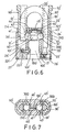
- the padlock according to a second preferred embodiment of this invention is shown to include a lock base 20', a lock unit 100', a shackle 30', spring-loaded retaining means 222', catch means, and a pair of shackle guards 60'.
- the lock base 20' has upper and lower ends, substantially parallel first and second shackle insert holes 22', 25' extending from the upper end toward the lower end, and a lock receiving space 21' extending from the lower end toward the upper end.
- the lock receiving space 21' is disposed between and is generally parallel to the first and second shackle insert holes 22', 25'.
- the lock receiving space 21' has an upper section formed as a catch chamber 210' which extends between the shackle insert holes 22', 25'.
- the upper end of the lock base 20' has two opposite notches 24' which are formed respectively in lateral walls of the lock base 20' and which extend transversely to a respective one of the shackle insert holes 22', 25'.
- the lock unit 100' is received in the lock receiving space 21' and includes an axially rotatable key-operated lock core 105' which has an upper end provided with a plunger 101'.
- the plunger 101' is disposed in the catch chamber 210' and is generally rectangular in shape.
- the lock unit 100' has a peripheral portion formed with an engaging groove 102'.
- the shackle 30' has a spring-loaded longer leg portion 32' which is retained slidably and rotatably in the first shackle insert hole 22', and a shorter leg portion 35' which is received removably in the second shackle insert hole 25'.
- Each of the longer and shorter leg portions 32', 35' is formed with a curved locking notch 31' at an inner side thereof.
- the second shackle insert hole 25' has an innermost end formed as a retainer hole portion 221' with the retaining means 222' disposed therein.
- the retaining means 222' includes a compression spring having a first end secured to a wall of the retainer hole portion 221', and a retaining member connected to a second end of the compression spring opposite to the first end.
- the retaining means 222' extends radially into the lock receiving space 21' to engage the engaging groove 102' in the lock unit 100' so as to retain releasably the lock unit 100' in the lock receiving space 21'.
- the catch means includes first and second catch units 40' which are disposed in the catch chamber 210' on opposite sides of the plunger 101', and a spring 45'.
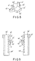
- Each of the first and second catch units 40' includes a frame with two downwardly extending, parallel arms 41', a horizontal plate 42' extending from upper ends of the arms 41' toward the other one of the catch units 40', and a ball member 300.
- the parallel arms 41' of each of the catch units 40' have concave retaining faces 412' for retaining the ball member 300 therebetween.
- the horizontal plate 42' has a top side formed with a hook projection 44' which has a respective end of the spring 45' hooked thereon for pulling together the frames of the first and second catch units 40' such that the ball members 300 of the first and second catch units 40' engage the plunger 101'.
- the frame of each of the catch units 40' is further formed with two opposite pawl projections 43' which protrude from two opposite sides of the horizontal plate 42'.
- the shackle guards 60' are disposed slidably and respectively in the shackle insert holes 22', 25', and are similar in shape to the shackle guards 60 in the previous embodiment.
- the shackle guards 60' are formed with ratchet teeth 61' along longitudinal edges thereof for engaging the pawl projections 43' of the catch units 40'.
- Each of the longitudinal edges of the shackle guards 60' is formed with a U-shaped retaining groove 611' adjacent to a lowermost one of the ratchet teeth 61'.
- Each of the shackle guards 60' is further formed with an outwardly protruding push projection 62' at an upper end thereof to permit pushing of the shackle guards 60' upwardly for extension out of the shackle insert holes 22', 25'.
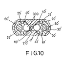
- the lock core 105' of the lock unit 100' is rotatable when operated by the correct key (not shown) so as to rotate the plunger 101' between a locking position as shown in Figures 6 and 7, and an unlocking position as shown in Figure 10.
- the plunger 101' forces apart the first and the second catch units 40' against action of the spring 45' so as to extend the first and second catch units 40' into the shackle insert holes 22', 25' such that the ball members 300 engage the locking notches 31' in the longer and shorter leg portions 32', 35' of the shackle 30'.
- the pawl projections 43' of the first and second catch units 40' extend respectively into the shackle insert holes 22', 25' to engage the ratchet teeth 61' on the shackle guards 60' so that the shackle guards 60' can be prevented from moving downward and retracting into the shackle insert holes 22', 25' and so that the shackle guards 60' can be moved upwardly by pushing the push projections 62' in order to enclose respectively outer sides of the longer and shorter leg portions 32', 35' of the shackle 30'.
- the retaining grooves 611' on the shackle guards 60' limit extension of the shackle guards 60' so as to prevent separation of the shackle guards 60' from the lock base 20' during upward movement of the shackle guards 60'.
- the plunger 101' when the plunger 101' is in the unlocking position, the plunger 101' ceases to force apart the first and second catch units 40', thereby retracting the first and second catch units 40' into the catch chamber 210' by virtue of the spring 45' (see Figure 6) in order to permit upward movement of the longer leg portion 32' and removal of the shorter leg portion 35' from the second shackle insert hole 25'.
- the pawl projections 43' on the catch units 40' are retracted into the catch chamber 210' and disengage the ratchet teeth 61' on the shackle guards 60' so as to permit retraction of the shackle guards 60' into the shackle insert holes 22', 25' by virtue of gravity in order to expose the longer and shorter leg portions 32', 35' of the shackle 30'.
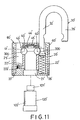
- the push projections 62' are received fittingly and respectively in the notches 24' of the lock base 20' (see Figure 11).
- the lock unit 100' when the lock unit 100' has corroded, is damaged, or when the lock unit 100' does not work for some reason, it can be removed from the lock receiving space 21' of the lock base 20' for replacement with a new one. Removal of the lock unit 100' is conducted in the following manner: After the shorter leg portion 35' of the shackle 30' has been removed from the second shackle insert hole 25' of the lock base 20', the longer leg portion 32' is rotated axially in the first shackle insert hole 22' to expose an upper section of the second shackle insert hole 25'.
- a tool (not shown) is inserted into the retainer hole portion 221' of the second shackle insert hole 25' so as to access and actuate the retaining means 222' against biasing force of the compression spring, thereby disengaging the retaining means 222' from the engaging groove 102' in the lock unit 100'.
- the lock unit 100' is thus removable from the lock receiving space 21' at this time.
- the padlock of the present invention permits quick and easy replacement of a lock unit with a new one when the current lock unit has become ineffective, thereby obviating the need for replacing the entire padlock to result in cost savings.
- the padlock of the present invention can provide an enhanced anti-theft effect.
- the lower end of the lock base 20' is formed with a cover recess 26' to mount a bottom cover 27' fittingly therein, such as by welding.
- the retainer hole portion 221' is formed in the bottom cover 27'.
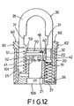
- Figure 12 illustrates the third preferred embodiment of a padlock according to this invention.
- the upper end of the lock base 20 is not formed with opposite notches for receiving fittingly and respectively the push projections 62 on the shackle guards 60.
- the lower end of the lock base 20 is formed with a cover recess 26 to mount a bottom cover 27 fittingly therein, such as by welding. Since the operation of the third preferred embodiment is similar to that of the first preferred embodiment, a description of the same will be obviated herein.
Landscapes
- Engineering & Computer Science (AREA)
- Mechanical Engineering (AREA)
- Refuge Islands, Traffic Blockers, Or Guard Fence (AREA)
- Maintenance And Inspection Apparatuses For Elevators (AREA)
- Preventing Unauthorised Actuation Of Valves (AREA)
- Driving Mechanisms And Operating Circuits Of Arc-Extinguishing High-Tension Switches (AREA)
- Lock And Its Accessories (AREA)
- Electrophonic Musical Instruments (AREA)
Claims (5)
- Bügelschloss, umfassend:eine Schlossbasis (20) mit einem ersten und einem zweiten Bügeleinführloch (22, 25) und einem Schlossaufnahmeraum (21);eine Schlosseinheit (100), die im Schlossaufnahmeraum (21) aufgenommen wird;einen Bügel (30) mit einem längeren Schenkelteil (32), der verschiebbar und drehbar im ersten Bügeleinführloch (22) gehalten wird, und einem kürzeren Schenkelteil (35), der entfernbar im zweiten Bügeleinführloch (25) aufgenommen wird;federvorgespannte Rückhaltemittel (222'), die auf der Schlossbasis (20) befestigt sind und sich in den Schlossaufnahmeraum (21) erstrecken, um mit der Schlosseinheit (100) in Eingriff zu kommen, um so die Schlosseinheit (100) lösbar im Schlossaufnahmeraum (21) zu halten, wobei die Rückhaltemittel (222') mittels eines Werkzeugs (200) zugänglich sind, das in das zweite Bügeleinführloch (25) eingeführt wird, wenn der kürzere Schenkelteil (35) des Bügels (30) aus dem Bügeleinführloch (25) entfernt ist, und dazu ausgelegt sind, durch das Werkzeug (200) betätigt zu werden, um die Schlosseinheit (100) zu lösen, um ein Entfernen der Schlosseinheit (100) aus dem Schlossaufnahmeraum (21) zu erlauben;wobei die Schlossbasis (20) ein oberes und ein unteres Ende aufweist, wobei sich das erste und das zweite Bügeleinführloch (22, 25) vom oberen Ende zum unteren Ende hin erstrecken, wobei sich der Schlossaufnahmeraum (21) vom unteren Ende zum oberen Ende hin erstreckt und zwischen den Bügeleinführlöchern (22, 25) angeordnet ist, wobei der Schlossaufnahmeraum (21) einen oberen Abschnitt aufweist, der als eine Riegelkammer (210) ausgebildet ist, die sich zwischen den Bügeleinführlöchern (22, 25) erstreckt, wobei die Schlosseinheit (100) einen axial drehbaren, mit einem Schlüssel zu betätigenden Schlosskern (105) aufweist, der mit einem Bolzen (101) versehen ist, der in der Riegelkammer (210) angeordnet ist, wobei die Rückhaltemittel in der Riegelkammer (210) angeordnet sind und Folgendes aufweisen:dadurch gekennzeichnet, dass das Bügelschloss weiter umfasst: ein Paar länglicher Bügelschützer (60), die verschiebbar jeweils in den Bügeleinführlöchern (22, 25) angeordnet sind, wobei jeder der Bügelschützer (60) mit an ihnen entlang verlaufenden Sperrklinkenzähnen (61) ausgebildet ist, wobei das äußere Ende eines jeden der Riegelglieder (40, 50) weiter mit einem Sperrklinkenfortsatz (43, 53) ausgebildet ist, der sich in ein jeweiliges der Bügeleinführlöcher (22, 25) hinein erstreckt, um mit den Sperrklinkenzähnen (61) auf einem entsprechenden der Bügelschützer (60) in Eingriff zu kommen, so dass die Bügelschützer (60) daran gehindert werden können, in die Bügeleinführlöcher (22, 25) zurück geschoben zu werden, und so dass die Bügelschützer (60) nach oben bewegt werden können, um die jeweiligen Außenseiten des längeren und des kürzeren Schenkelteils (32, 35) des Bügels (30) einzuschließen, wenn der Schlosskern (105) in der Verriegelungsposition ist, wobei der Sperrklinkenfortsatz (43, 53) auf den Riegelgliedern (40, 50) in die Riegelkammer (210) zurück gezogen wird, um die Sperrklinkenzähne (61) auf den jeweiligen Bügelschützern (60) außer Eingriff zu bringen, um ein Zurückschieben der Bügelschützer (60) in die Bügeleinführlöcher (22, 25) zu erlauben, um den längeren und den kürzeren Schenkelteil (32, 35) des Bügels (30) freizugeben, wenn der Schlosskern (105) in der Entriegelungsposition ist.ein erstes und ein zweites Riegelglied (40, 50), von denen jeweils ein äußeres Ende mit einem mit dem Bügel in Eingriff kommenden Teil (42, 52) ausgebildet ist, um mit dem längeren bzw. dem kürzeren Schenkelteil (32, 35) des Bügels (30) in Eingriff zu kommen, und ein inneres Ende mit einem mit dem Bolzen in Eingriff kommenden Teil (41, 51) ausgebildet ist, um mit dem Bolzen (101) des Schlosskerns (105) in Eingriff zu kommen;Federmittel (45, 55) zum Vorspannen des ersten und des zweiten Riegelglieds (40, 50), so dass die mit dem Bügel in Eingriff kommenden Teile (42, 52) sich federnd jeweils in die Bügeleinführlöcher (22, 25) hinein erstrecken,wobei der Schlosskern (105) so drehbar ist, dass der Bolzen (101) drehbar ist zwischen einer Verriegelungsposition, in der der Bolzen (101) das erste und das zweite Riegelglied (40, 50) auseinanderdrückt, um ein Zurückziehen der mit dem Bügel in Eingriff kommenden Teile (42, 52) in die Riegelkammer (210) zu verhindern, um so eine Aufwärtsbewegung des längeren Teils (32) im ersten Bügeleinführloch (22) zu verhindern, um ein Entfernen des kürzeren Schenkelteils (35) aus dem zweiten Bügeleinführloch (25) zu verhindern, und einer Entriegelungsposition, bei der der Bolzen (101) ein Zurückziehen der mit dem Bügel in Eingriff kommenden Teile (42, 52) des ersten und des zweiten Riegelglieds (40, 50) in die Riegelkammer (210) erlaubt, um eine Aufwärtsbewegung des längeren Schenkelteils (32) im ersten Bügeleinführloch (22) und ein Entfernen des kürzeren Schenkelteils (35) aus dem zweiten Bügeleinführloch (25) heraus zu erlauben;
- Bügelschloss nach Anspruch 1, bei dem bei jedem der Bügelschützer (60) ein oberes Ende mit einem nach außen vorstehenden Schiebefortsatz (62) ausgebildet ist, um ein Schieben der Bügelschützer (60) nach oben zu einer Erstreckung aus den Bügeleinführlöchern (22, 25) heraus zu erlauben, wobei das obere Ende der Schlossbasis (20) mit zwei Ausnehmungen (24) zum Aufnehmen der Schiebefortsätze (62) ausgebildet ist, wenn die Bügelschützer (60) in die Bügeleinführlöcher (22, 25) eingeschoben sind.
- Bügelschloss nach entweder Anspruch 1 oder Anspruch 2, bei dem der Bolzen (101) des Schlosskerns (105) einen breiteren oberen Abschnitt (101a) und einen schmaleren unteren Abschnitt (101b) aufweist, wobei die mit dem Bolzen (101) in Eingriff kommenden Teile (41, 51) des ersten und des zweiten Riegelglieds (40, 50) zusammenwirkend eine Eingriffsnut (A) bilden, die mit dem Bolzen (101) konform ist, um den Schlosskern (105) im Schlossaufnahmeraum (21) zurück zu halten.
- Bügelschloss nach einem der vorhergehenden Ansprüche, bei dem das erste und das zweite Riegelglied (40, 50) nebeneinander in der Riegelkammer (210) angeordnet sind, wobei der mit dem Bolzen in Eingriff kommende Teil (41, 51) eines jeden des ersten und des zweiten Riegelglieds (40, 50) sich zwischen dem mit dem Bolzen in Eingriff kommenden Teil (41, 51) und dem mit dem Bügel in Eingriff kommenden Teil (42, 52) des jeweils anderen des ersten und des zweiten Riegelglieds (40, 50) erstreckt, wobei der mit dem Bügel in Eingriff kommende Teil (52) des zweiten Riegelglieds (50) unter Zwang mittels des Werkzeugs (200) in die Riegelkammer (210) zurückziehbar ist, wenn der Bolzen (101) in der Entriegelungsposition ist und der kürzere Schenkelteil (35) des Bügels (30) aus dem zweiten Bügeleinführloch (25) entfernt ist, um den Bolzen (101) des Schlosskerns (105) mit den mit dem Bolzen in Eingriff kommenden Teilen (41, 51) des ersten und des zweiten Riegelglieds (40, 50) außer Eingriff zu bringen und um ein Entfernen der Schlosseinheit (100) aus dem Schlossaufnahmeraum (21) zu erlauben.
- Bügelschloss nach einem der vorhergehenden Ansprüche, bei dem die Federmittel eine erste und eine zweite Vorspannfeder (45, 55) aufweisen, von denen jede zwischen dem mit dem Bolzen in Eingriff kommenden Teil (41, 51) des ersten und des zweiten Riegelglieds (40, 50) und dem mit dem Bügel in Eingriff kommenden Teil (42, 52) des jeweils anderen des ersten und des zweiten Riegelglieds (40, 50) angeordnet ist, wodurch die mit dem Bügel in Eingriff kommenden Teile (42, 52) so vorgespannt werden, dass sie sich in die jeweiligen Bügeleinführlöcher (22, 25) hinein erstrecken, und wodurch die mit dem Bolzen in Eingriff kommenden Teile (41, 51) so vorgespannt werden, dass sie jeweils mit den entgegengesetzten Seiten des Bolzens (101) in Eingriff kommen.
Priority Applications (6)
| Application Number | Priority Date | Filing Date | Title |
|---|---|---|---|
| ZA9708882A ZA978882B (en) | 1997-10-03 | 1997-10-03 | Padlock with replaceable key-operated lock core. |
| US08/992,444 US5931030A (en) | 1997-10-03 | 1997-12-17 | Padlock with replaceable key-operated lock core |
| DE1998617332 DE69817332T2 (de) | 1997-10-03 | 1998-06-12 | Hängeschloss mit auswechselbarem schlüsselbetätigtem Zylinderkern |
| CA 2240586 CA2240586C (en) | 1997-10-03 | 1998-06-12 | Padlock with replaceable key-operated lock core |
| EP98304670A EP0964123B1 (de) | 1997-10-03 | 1998-06-12 | Hängeschloss mit auswechselbarem schlüsselbetätigtem Zylinderkern |
| AT98304670T ATE247759T1 (de) | 1997-10-03 | 1998-06-12 | Hängeschloss mit auswechselbarem schlüsselbetätigtem zylinderkern |
Applications Claiming Priority (4)
| Application Number | Priority Date | Filing Date | Title |
|---|---|---|---|
| ZA9708882A ZA978882B (en) | 1997-10-03 | 1997-10-03 | Padlock with replaceable key-operated lock core. |
| US08/992,444 US5931030A (en) | 1997-10-03 | 1997-12-17 | Padlock with replaceable key-operated lock core |
| CA 2240586 CA2240586C (en) | 1997-10-03 | 1998-06-12 | Padlock with replaceable key-operated lock core |
| EP98304670A EP0964123B1 (de) | 1997-10-03 | 1998-06-12 | Hängeschloss mit auswechselbarem schlüsselbetätigtem Zylinderkern |
Publications (2)
| Publication Number | Publication Date |
|---|---|
| EP0964123A1 EP0964123A1 (de) | 1999-12-15 |
| EP0964123B1 true EP0964123B1 (de) | 2003-08-20 |
Family
ID=33033173
Family Applications (1)
| Application Number | Title | Priority Date | Filing Date |
|---|---|---|---|
| EP98304670A Expired - Lifetime EP0964123B1 (de) | 1997-10-03 | 1998-06-12 | Hängeschloss mit auswechselbarem schlüsselbetätigtem Zylinderkern |
Country Status (6)
| Country | Link |
|---|---|
| US (1) | US5931030A (de) |
| EP (1) | EP0964123B1 (de) |
| AT (1) | ATE247759T1 (de) |
| CA (1) | CA2240586C (de) |
| DE (1) | DE69817332T2 (de) |
| ZA (1) | ZA978882B (de) |
Families Citing this family (26)
| Publication number | Priority date | Publication date | Assignee | Title |
|---|---|---|---|---|
| DE10026701A1 (de) * | 2000-05-30 | 2001-12-06 | Bremicker Soehne Kg A | Bügelschloß |
| AU750069B1 (en) * | 2001-07-23 | 2002-07-11 | Waterson Chen | Impact resistant lock apparatus with anti-theft lock core |
| ATE329109T1 (de) * | 2001-10-18 | 2006-06-15 | Waterson Chen | Vorhängeschloss mit einem u-förmigen schlossgehäuse |
| US6679086B1 (en) * | 2002-08-27 | 2004-01-20 | Charles Richard Hart, Jr. | Protective sheath for padlock |
| TWI224647B (en) * | 2003-04-03 | 2004-12-01 | Waterson Corp | A padlock device |
| WO2004104329A2 (en) * | 2003-05-16 | 2004-12-02 | Stanton Concepts Inc. | Multiple function lock |
| US7424812B2 (en) * | 2003-05-16 | 2008-09-16 | Stanton Concepts Inc. | Multiple function lock |
| US7021092B2 (en) | 2003-05-16 | 2006-04-04 | Stanton Concepts Inc. | Multiple function lock |
| US7434426B2 (en) * | 2003-05-16 | 2008-10-14 | Stanton Concepts Inc. | Multiple function lock |
| US7694542B2 (en) | 2004-07-22 | 2010-04-13 | Stanton Concepts Inc. | Tool operated combination lock |
| US7712342B2 (en) | 2004-07-22 | 2010-05-11 | Stanton Concepts Inc. | Tool operated combination lock |
| MX2007005923A (es) * | 2004-11-18 | 2007-06-19 | Master Lock Co | Candado con refuerzo movil. |
| US20060185404A1 (en) * | 2005-02-18 | 2006-08-24 | Hansen Randall C | Codeable padlock |
| US7047773B1 (en) * | 2005-06-07 | 2006-05-23 | Fu Chuan Lin | Combination lock and padlock combination |
| DE102009030031A1 (de) * | 2009-06-23 | 2010-12-30 | ABUS August Bremicker Söhne KG | Bügelschloss |
| US20120234062A1 (en) * | 2009-10-02 | 2012-09-20 | Stanton Concepts, L.L.C. | Dual Custody Privacy Padlock |
| US20110126385A1 (en) * | 2009-11-17 | 2011-06-02 | Martin Nathan | Security Clasp |
| US8245547B1 (en) * | 2011-01-27 | 2012-08-21 | ABUS August Bremicker Söhne KG | Padlock |
| FI125353B (fi) * | 2013-06-28 | 2015-09-15 | Abloy Oy | Riippulukkosuoja |
| WO2015192013A1 (en) * | 2014-06-12 | 2015-12-17 | Schlage Lock Company Llc | Hoop lock with dual locking |
| US9464462B1 (en) * | 2015-10-30 | 2016-10-11 | Federal Lock Co., Ltd. | Padlock with non-conductive parts |
| TWI745456B (zh) | 2016-10-19 | 2021-11-11 | 美商貝斯特艾瑟斯解決方案股份有限公司 | 電機式鎖芯裝置、系統及操作電機式鎖芯裝置之方法 |
| WO2019051337A1 (en) | 2017-09-08 | 2019-03-14 | Dormakaba Usa Inc. | CENTRAL ELECTROMECHANICAL LOCK SECTION |
| US10648196B2 (en) | 2018-01-31 | 2020-05-12 | Master Lock Company Llc | Lockbox with multi-position shackle |
| CN112752891B (zh) | 2018-04-13 | 2022-08-05 | 多玛卡巴美国公司 | 机电锁芯 |
| US11466473B2 (en) | 2018-04-13 | 2022-10-11 | Dormakaba Usa Inc | Electro-mechanical lock core |
Family Cites Families (23)
| Publication number | Priority date | Publication date | Assignee | Title |
|---|---|---|---|---|
| US1824301A (en) * | 1928-07-23 | 1931-09-22 | Unit Lock Company | Padlock |
| US2047969A (en) * | 1934-02-20 | 1936-07-21 | Keil Francis & Son Inc | Lock construction |
| US2199336A (en) * | 1939-12-11 | 1940-04-30 | American Hardware Corp | Lock |
| GB550596A (en) * | 1941-08-30 | 1943-01-15 | Yale & Towne Mfg Co | Improvements in and relating to padlock cylinder retainers |
| US2557028A (en) * | 1946-02-09 | 1951-06-12 | Deutsch Lock Company | Key-operable permutation lock |
| FR953722A (fr) * | 1947-02-04 | 1949-12-12 | Cadenas | |
| US2541638A (en) * | 1948-04-26 | 1951-02-13 | Wallace G Clevett | Padlock shield and shielded padlock assembly |
| US2691288A (en) * | 1951-11-26 | 1954-10-12 | Schlage Lock Co | Padlock |
| US3068682A (en) * | 1960-09-12 | 1962-12-18 | Russell | Padlock with dual blockers |
| US3172279A (en) * | 1962-11-07 | 1965-03-09 | Independent Lock Co | Padlock assembly |
| US3254516A (en) * | 1964-05-04 | 1966-06-07 | Schlage Lock Co | Padlock |
| US3505837A (en) * | 1968-10-02 | 1970-04-14 | Norris Industries | Padlock picking guard and driver spacer |
| US3793856A (en) * | 1972-10-13 | 1974-02-26 | Junkunc Bros American Lock Co | Padlock and key cylinder release |
| US4098100A (en) * | 1977-04-20 | 1978-07-04 | Man Wah | Laminated padlock |
| US4138868A (en) * | 1977-08-19 | 1979-02-13 | Richards Sr Frederick F | Replaceable cylinder padlock |
| US4290280A (en) * | 1979-03-23 | 1981-09-22 | Yun Sun Y | Padlock |
| US4345447A (en) * | 1980-11-03 | 1982-08-24 | Keung Poon C | Double lock |
| IL64355A (en) * | 1981-11-25 | 1986-01-31 | Bahry Abraham | Protective hasps for padlock |
| US4811578A (en) * | 1983-08-18 | 1989-03-14 | John F. Masoncup | Padlock with tamper-actuated audible and/or inaudible alarm |
| US4776187A (en) * | 1987-05-27 | 1988-10-11 | Sargent & Greenleaf, Inc. | Changeable key cylinder exposed shackle padlock |
| US4763496A (en) * | 1987-05-27 | 1988-08-16 | Sargent & Greenleaf, Inc. | High security changeable key cylinder type shackle padlock |
| US4998422A (en) * | 1989-08-30 | 1991-03-12 | Best Lock Corporation | Removable core padlock with bolt retainer |
| US5363678A (en) * | 1993-04-09 | 1994-11-15 | Abus August Bremicker Sohne Kg | Padlock with ball-locked shackle |
-
1997
- 1997-10-03 ZA ZA9708882A patent/ZA978882B/xx unknown
- 1997-12-17 US US08/992,444 patent/US5931030A/en not_active Expired - Fee Related
-
1998
- 1998-06-12 EP EP98304670A patent/EP0964123B1/de not_active Expired - Lifetime
- 1998-06-12 AT AT98304670T patent/ATE247759T1/de not_active IP Right Cessation
- 1998-06-12 CA CA 2240586 patent/CA2240586C/en not_active Expired - Fee Related
- 1998-06-12 DE DE1998617332 patent/DE69817332T2/de not_active Expired - Fee Related
Also Published As
| Publication number | Publication date |
|---|---|
| ZA978882B (en) | 1998-06-24 |
| DE69817332T2 (de) | 2004-04-08 |
| EP0964123A1 (de) | 1999-12-15 |
| ATE247759T1 (de) | 2003-09-15 |
| US5931030A (en) | 1999-08-03 |
| CA2240586A1 (en) | 1999-12-12 |
| DE69817332D1 (de) | 2003-09-25 |
| CA2240586C (en) | 2002-04-23 |
Similar Documents
| Publication | Publication Date | Title |
|---|---|---|
| EP0964123B1 (de) | Hängeschloss mit auswechselbarem schlüsselbetätigtem Zylinderkern | |
| US5896761A (en) | Padlock | |
| US5417092A (en) | Padlock | |
| US5720191A (en) | Padlock | |
| JP2008519927A (ja) | 鍵再設定可能な錠シリンダ | |
| US4404825A (en) | Padlock having a replaceable cylinder | |
| US5640861A (en) | Motorcycle lock | |
| US20040107744A1 (en) | Lock assembly | |
| WO2005019041A2 (en) | Security cover with releasable lock | |
| WO2011127536A1 (en) | A wear assembly | |
| US5231236A (en) | Safety lock for firearms | |
| US8152036B2 (en) | Case assembly for motorcycle including a coupling system | |
| EP1365091A1 (de) | Hängeschloss mit flexiblem Bügel und auswechselbarem Zylinderkern | |
| AU754316B2 (en) | Padlock with replaceable key-operated lock core | |
| US20070224010A1 (en) | Locking device for securing loads | |
| US5297404A (en) | Bolt for an inner cylinder lock | |
| US6595032B2 (en) | Lock cylinder-free lock device | |
| EP0971087A1 (de) | Vorhängeschloss | |
| MXPA98005028A (en) | Padlock with replaceable lock nucleus, operated by ll | |
| US6199416B1 (en) | Motorcycle lock | |
| WO2004059111A1 (en) | Safety catch for mortise lock | |
| EP1304434B1 (de) | Vorhängeschloss mit einem U-förmigen Schlossgehäuse | |
| WO2005099349A2 (en) | Improved hasps, shackles, and padlocks | |
| US5329794A (en) | Automobile steering lock | |
| US20080236218A1 (en) | Steering Wheel Locking Device |
Legal Events
| Date | Code | Title | Description |
|---|---|---|---|
| PUAI | Public reference made under article 153(3) epc to a published international application that has entered the european phase |
Free format text: ORIGINAL CODE: 0009012 |
|
| 17P | Request for examination filed |
Effective date: 19980626 |
|
| AK | Designated contracting states |
Kind code of ref document: A1 Designated state(s): AT BE CH CY DE DK ES FI FR GB GR IE IT LI LU MC NL PT SE |
|
| AX | Request for extension of the european patent |
Free format text: AL;LT;LV;MK;RO;SI |
|
| EUG | Se: european patent has lapsed | ||
| AKX | Designation fees paid |
Free format text: AT BE CH CY DE DK ES FI FR GB GR IE IT LI LU MC NL PT SE |
|
| 17Q | First examination report despatched |
Effective date: 20020418 |
|
| GRAH | Despatch of communication of intention to grant a patent |
Free format text: ORIGINAL CODE: EPIDOS IGRA |
|
| GRAH | Despatch of communication of intention to grant a patent |
Free format text: ORIGINAL CODE: EPIDOS IGRA |
|
| GRAA | (expected) grant |
Free format text: ORIGINAL CODE: 0009210 |
|
| AK | Designated contracting states |
Designated state(s): AT BE CH CY DE DK ES FI FR GB GR IE IT LI LU MC NL PT SE |
|
| PG25 | Lapsed in a contracting state [announced via postgrant information from national office to epo] |
Ref country code: NL Free format text: LAPSE BECAUSE OF FAILURE TO SUBMIT A TRANSLATION OF THE DESCRIPTION OR TO PAY THE FEE WITHIN THE PRESCRIBED TIME-LIMIT Effective date: 20030820 Ref country code: LI Free format text: LAPSE BECAUSE OF FAILURE TO SUBMIT A TRANSLATION OF THE DESCRIPTION OR TO PAY THE FEE WITHIN THE PRESCRIBED TIME-LIMIT Effective date: 20030820 Ref country code: CY Free format text: LAPSE BECAUSE OF FAILURE TO SUBMIT A TRANSLATION OF THE DESCRIPTION OR TO PAY THE FEE WITHIN THE PRESCRIBED TIME-LIMIT Effective date: 20030820 Ref country code: CH Free format text: LAPSE BECAUSE OF FAILURE TO SUBMIT A TRANSLATION OF THE DESCRIPTION OR TO PAY THE FEE WITHIN THE PRESCRIBED TIME-LIMIT Effective date: 20030820 Ref country code: BE Free format text: LAPSE BECAUSE OF FAILURE TO SUBMIT A TRANSLATION OF THE DESCRIPTION OR TO PAY THE FEE WITHIN THE PRESCRIBED TIME-LIMIT Effective date: 20030820 Ref country code: AT Free format text: LAPSE BECAUSE OF FAILURE TO SUBMIT A TRANSLATION OF THE DESCRIPTION OR TO PAY THE FEE WITHIN THE PRESCRIBED TIME-LIMIT Effective date: 20030820 |
|
| REG | Reference to a national code |
Ref country code: GB Ref legal event code: FG4D |
|
| REG | Reference to a national code |
Ref country code: CH Ref legal event code: EP |
|
| REG | Reference to a national code |
Ref country code: IE Ref legal event code: FG4D |
|
| REF | Corresponds to: |
Ref document number: 69817332 Country of ref document: DE Date of ref document: 20030925 Kind code of ref document: P |
|
| PG25 | Lapsed in a contracting state [announced via postgrant information from national office to epo] |
Ref country code: GR Free format text: LAPSE BECAUSE OF FAILURE TO SUBMIT A TRANSLATION OF THE DESCRIPTION OR TO PAY THE FEE WITHIN THE PRESCRIBED TIME-LIMIT Effective date: 20031120 Ref country code: DK Free format text: LAPSE BECAUSE OF FAILURE TO SUBMIT A TRANSLATION OF THE DESCRIPTION OR TO PAY THE FEE WITHIN THE PRESCRIBED TIME-LIMIT Effective date: 20031120 |
|
| PG25 | Lapsed in a contracting state [announced via postgrant information from national office to epo] |
Ref country code: ES Free format text: LAPSE BECAUSE OF FAILURE TO SUBMIT A TRANSLATION OF THE DESCRIPTION OR TO PAY THE FEE WITHIN THE PRESCRIBED TIME-LIMIT Effective date: 20031201 |
|
| REG | Reference to a national code |
Ref country code: SE Ref legal event code: TRGR |
|
| PG25 | Lapsed in a contracting state [announced via postgrant information from national office to epo] |
Ref country code: PT Free format text: LAPSE BECAUSE OF FAILURE TO SUBMIT A TRANSLATION OF THE DESCRIPTION OR TO PAY THE FEE WITHIN THE PRESCRIBED TIME-LIMIT Effective date: 20040120 |
|
| NLV1 | Nl: lapsed or annulled due to failure to fulfill the requirements of art. 29p and 29m of the patents act | ||
| REG | Reference to a national code |
Ref country code: CH Ref legal event code: PL |
|
| ET | Fr: translation filed | ||
| PG25 | Lapsed in a contracting state [announced via postgrant information from national office to epo] |
Ref country code: LU Free format text: LAPSE BECAUSE OF NON-PAYMENT OF DUE FEES Effective date: 20040612 |
|
| PG25 | Lapsed in a contracting state [announced via postgrant information from national office to epo] |
Ref country code: IE Free format text: LAPSE BECAUSE OF NON-PAYMENT OF DUE FEES Effective date: 20040614 |
|
| PLBE | No opposition filed within time limit |
Free format text: ORIGINAL CODE: 0009261 |
|
| STAA | Information on the status of an ep patent application or granted ep patent |
Free format text: STATUS: NO OPPOSITION FILED WITHIN TIME LIMIT |
|
| PG25 | Lapsed in a contracting state [announced via postgrant information from national office to epo] |
Ref country code: MC Free format text: LAPSE BECAUSE OF NON-PAYMENT OF DUE FEES Effective date: 20040630 |
|
| 26N | No opposition filed |
Effective date: 20040524 |
|
| REG | Reference to a national code |
Ref country code: IE Ref legal event code: MM4A |
|
| PGFP | Annual fee paid to national office [announced via postgrant information from national office to epo] |
Ref country code: SE Payment date: 20060607 Year of fee payment: 9 Ref country code: GB Payment date: 20060607 Year of fee payment: 9 |
|
| PGFP | Annual fee paid to national office [announced via postgrant information from national office to epo] |
Ref country code: FR Payment date: 20060608 Year of fee payment: 9 Ref country code: DE Payment date: 20060608 Year of fee payment: 9 |
|
| PGFP | Annual fee paid to national office [announced via postgrant information from national office to epo] |
Ref country code: FI Payment date: 20060614 Year of fee payment: 9 |
|
| PGFP | Annual fee paid to national office [announced via postgrant information from national office to epo] |
Ref country code: IT Payment date: 20060630 Year of fee payment: 9 |
|
| PG25 | Lapsed in a contracting state [announced via postgrant information from national office to epo] |
Ref country code: FI Free format text: LAPSE BECAUSE OF NON-PAYMENT OF DUE FEES Effective date: 20070612 |
|
| EUG | Se: european patent has lapsed | ||
| GBPC | Gb: european patent ceased through non-payment of renewal fee |
Effective date: 20070612 |
|
| REG | Reference to a national code |
Ref country code: FR Ref legal event code: ST Effective date: 20080229 |
|
| PG25 | Lapsed in a contracting state [announced via postgrant information from national office to epo] |
Ref country code: DE Free format text: LAPSE BECAUSE OF NON-PAYMENT OF DUE FEES Effective date: 20080101 |
|
| PG25 | Lapsed in a contracting state [announced via postgrant information from national office to epo] |
Ref country code: GB Free format text: LAPSE BECAUSE OF NON-PAYMENT OF DUE FEES Effective date: 20070612 |
|
| PG25 | Lapsed in a contracting state [announced via postgrant information from national office to epo] |
Ref country code: SE Free format text: LAPSE BECAUSE OF NON-PAYMENT OF DUE FEES Effective date: 20070613 |
|
| PG25 | Lapsed in a contracting state [announced via postgrant information from national office to epo] |
Ref country code: FR Free format text: LAPSE BECAUSE OF NON-PAYMENT OF DUE FEES Effective date: 20070702 |
|
| PG25 | Lapsed in a contracting state [announced via postgrant information from national office to epo] |
Ref country code: IT Free format text: LAPSE BECAUSE OF NON-PAYMENT OF DUE FEES Effective date: 20070612 |