EP0964172B1 - Méthode pour modifier la précharge d'un membre rotatif et membre rotatif - Google Patents
Méthode pour modifier la précharge d'un membre rotatif et membre rotatif Download PDFInfo
- Publication number
- EP0964172B1 EP0964172B1 EP99110821A EP99110821A EP0964172B1 EP 0964172 B1 EP0964172 B1 EP 0964172B1 EP 99110821 A EP99110821 A EP 99110821A EP 99110821 A EP99110821 A EP 99110821A EP 0964172 B1 EP0964172 B1 EP 0964172B1
- Authority
- EP
- European Patent Office
- Prior art keywords
- rotating component
- adjustment unit
- shaft bearing
- axial
- radial
- Prior art date
- Legal status (The legal status is an assumption and is not a legal conclusion. Google has not performed a legal analysis and makes no representation as to the accuracy of the status listed.)
- Expired - Lifetime
Links
- 238000000034 method Methods 0.000 title claims description 12
- 230000036316 preload Effects 0.000 title 1
- 230000006870 function Effects 0.000 claims description 11
- 238000012546 transfer Methods 0.000 claims description 8
- 238000002485 combustion reaction Methods 0.000 claims description 6
- 230000002441 reversible effect Effects 0.000 claims description 3
- 239000011149 active material Substances 0.000 claims 4
- 230000010360 secondary oscillation Effects 0.000 description 10
- 239000011159 matrix material Substances 0.000 description 8
- 230000000875 corresponding effect Effects 0.000 description 7
- 230000005540 biological transmission Effects 0.000 description 6
- 230000001419 dependent effect Effects 0.000 description 5
- 238000010276 construction Methods 0.000 description 4
- 230000000694 effects Effects 0.000 description 4
- 239000010410 layer Substances 0.000 description 3
- 239000000463 material Substances 0.000 description 3
- 229920000642 polymer Polymers 0.000 description 3
- 239000002131 composite material Substances 0.000 description 2
- 238000013461 design Methods 0.000 description 2
- 230000000977 initiatory effect Effects 0.000 description 2
- 239000012791 sliding layer Substances 0.000 description 2
- KGBXLFKZBHKPEV-UHFFFAOYSA-N boric acid Chemical compound OB(O)O KGBXLFKZBHKPEV-UHFFFAOYSA-N 0.000 description 1
- 230000001276 controlling effect Effects 0.000 description 1
- 230000002596 correlated effect Effects 0.000 description 1
- 238000013500 data storage Methods 0.000 description 1
- 238000011161 development Methods 0.000 description 1
- 229920001971 elastomer Polymers 0.000 description 1
- 239000000806 elastomer Substances 0.000 description 1
- 230000005611 electricity Effects 0.000 description 1
- 238000011156 evaluation Methods 0.000 description 1
- 230000005284 excitation Effects 0.000 description 1
- 230000002349 favourable effect Effects 0.000 description 1
- 239000000314 lubricant Substances 0.000 description 1
- 238000004519 manufacturing process Methods 0.000 description 1
- 238000011089 mechanical engineering Methods 0.000 description 1
- 239000012528 membrane Substances 0.000 description 1
- 230000010355 oscillation Effects 0.000 description 1
- 230000008447 perception Effects 0.000 description 1
- 230000001681 protective effect Effects 0.000 description 1
- 238000007789 sealing Methods 0.000 description 1
- 230000003068 static effect Effects 0.000 description 1
- PTISTKLWEJDJID-UHFFFAOYSA-N sulfanylidenemolybdenum Chemical compound [Mo]=S PTISTKLWEJDJID-UHFFFAOYSA-N 0.000 description 1
- 230000001629 suppression Effects 0.000 description 1
- 238000010792 warming Methods 0.000 description 1
Images
Classifications
-
- F—MECHANICAL ENGINEERING; LIGHTING; HEATING; WEAPONS; BLASTING
- F16—ENGINEERING ELEMENTS AND UNITS; GENERAL MEASURES FOR PRODUCING AND MAINTAINING EFFECTIVE FUNCTIONING OF MACHINES OR INSTALLATIONS; THERMAL INSULATION IN GENERAL
- F16C—SHAFTS; FLEXIBLE SHAFTS; ELEMENTS OR CRANKSHAFT MECHANISMS; ROTARY BODIES OTHER THAN GEARING ELEMENTS; BEARINGS
- F16C27/00—Elastic or yielding bearings or bearing supports, for exclusively rotary movement
- F16C27/06—Elastic or yielding bearings or bearing supports, for exclusively rotary movement by means of parts of rubber or like materials
- F16C27/066—Ball or roller bearings
-
- B—PERFORMING OPERATIONS; TRANSPORTING
- B23—MACHINE TOOLS; METAL-WORKING NOT OTHERWISE PROVIDED FOR
- B23Q—DETAILS, COMPONENTS, OR ACCESSORIES FOR MACHINE TOOLS, e.g. ARRANGEMENTS FOR COPYING OR CONTROLLING; MACHINE TOOLS IN GENERAL CHARACTERISED BY THE CONSTRUCTION OF PARTICULAR DETAILS OR COMPONENTS; COMBINATIONS OR ASSOCIATIONS OF METAL-WORKING MACHINES, NOT DIRECTED TO A PARTICULAR RESULT
- B23Q1/00—Members which are comprised in the general build-up of a form of machine, particularly relatively large fixed members
- B23Q1/25—Movable or adjustable work or tool supports
- B23Q1/26—Movable or adjustable work or tool supports characterised by constructional features relating to the co-operation of relatively movable members; Means for preventing relative movement of such members
- B23Q1/262—Movable or adjustable work or tool supports characterised by constructional features relating to the co-operation of relatively movable members; Means for preventing relative movement of such members with means to adjust the distance between the relatively slidable members
- B23Q1/265—Movable or adjustable work or tool supports characterised by constructional features relating to the co-operation of relatively movable members; Means for preventing relative movement of such members with means to adjust the distance between the relatively slidable members between rotating members
-
- F—MECHANICAL ENGINEERING; LIGHTING; HEATING; WEAPONS; BLASTING
- F16—ENGINEERING ELEMENTS AND UNITS; GENERAL MEASURES FOR PRODUCING AND MAINTAINING EFFECTIVE FUNCTIONING OF MACHINES OR INSTALLATIONS; THERMAL INSULATION IN GENERAL
- F16C—SHAFTS; FLEXIBLE SHAFTS; ELEMENTS OR CRANKSHAFT MECHANISMS; ROTARY BODIES OTHER THAN GEARING ELEMENTS; BEARINGS
- F16C19/00—Bearings with rolling contact, for exclusively rotary movement
- F16C19/52—Bearings with rolling contact, for exclusively rotary movement with devices affected by abnormal or undesired conditions
-
- F—MECHANICAL ENGINEERING; LIGHTING; HEATING; WEAPONS; BLASTING
- F16—ENGINEERING ELEMENTS AND UNITS; GENERAL MEASURES FOR PRODUCING AND MAINTAINING EFFECTIVE FUNCTIONING OF MACHINES OR INSTALLATIONS; THERMAL INSULATION IN GENERAL
- F16C—SHAFTS; FLEXIBLE SHAFTS; ELEMENTS OR CRANKSHAFT MECHANISMS; ROTARY BODIES OTHER THAN GEARING ELEMENTS; BEARINGS
- F16C19/00—Bearings with rolling contact, for exclusively rotary movement
- F16C19/52—Bearings with rolling contact, for exclusively rotary movement with devices affected by abnormal or undesired conditions
- F16C19/527—Bearings with rolling contact, for exclusively rotary movement with devices affected by abnormal or undesired conditions related to vibration and noise
-
- F—MECHANICAL ENGINEERING; LIGHTING; HEATING; WEAPONS; BLASTING
- F16—ENGINEERING ELEMENTS AND UNITS; GENERAL MEASURES FOR PRODUCING AND MAINTAINING EFFECTIVE FUNCTIONING OF MACHINES OR INSTALLATIONS; THERMAL INSULATION IN GENERAL
- F16C—SHAFTS; FLEXIBLE SHAFTS; ELEMENTS OR CRANKSHAFT MECHANISMS; ROTARY BODIES OTHER THAN GEARING ELEMENTS; BEARINGS
- F16C23/00—Bearings for exclusively rotary movement adjustable for aligning or positioning
- F16C23/06—Ball or roller bearings
-
- F—MECHANICAL ENGINEERING; LIGHTING; HEATING; WEAPONS; BLASTING
- F16—ENGINEERING ELEMENTS AND UNITS; GENERAL MEASURES FOR PRODUCING AND MAINTAINING EFFECTIVE FUNCTIONING OF MACHINES OR INSTALLATIONS; THERMAL INSULATION IN GENERAL
- F16C—SHAFTS; FLEXIBLE SHAFTS; ELEMENTS OR CRANKSHAFT MECHANISMS; ROTARY BODIES OTHER THAN GEARING ELEMENTS; BEARINGS
- F16C25/00—Bearings for exclusively rotary movement adjustable for wear or play
- F16C25/06—Ball or roller bearings
-
- F—MECHANICAL ENGINEERING; LIGHTING; HEATING; WEAPONS; BLASTING
- F16—ENGINEERING ELEMENTS AND UNITS; GENERAL MEASURES FOR PRODUCING AND MAINTAINING EFFECTIVE FUNCTIONING OF MACHINES OR INSTALLATIONS; THERMAL INSULATION IN GENERAL
- F16C—SHAFTS; FLEXIBLE SHAFTS; ELEMENTS OR CRANKSHAFT MECHANISMS; ROTARY BODIES OTHER THAN GEARING ELEMENTS; BEARINGS
- F16C9/00—Bearings for crankshafts or connecting-rods; Attachment of connecting-rods
- F16C9/02—Crankshaft bearings
-
- F—MECHANICAL ENGINEERING; LIGHTING; HEATING; WEAPONS; BLASTING
- F16—ENGINEERING ELEMENTS AND UNITS; GENERAL MEASURES FOR PRODUCING AND MAINTAINING EFFECTIVE FUNCTIONING OF MACHINES OR INSTALLATIONS; THERMAL INSULATION IN GENERAL
- F16C—SHAFTS; FLEXIBLE SHAFTS; ELEMENTS OR CRANKSHAFT MECHANISMS; ROTARY BODIES OTHER THAN GEARING ELEMENTS; BEARINGS
- F16C9/00—Bearings for crankshafts or connecting-rods; Attachment of connecting-rods
- F16C9/02—Crankshaft bearings
- F16C9/03—Arrangements for adjusting play
-
- F—MECHANICAL ENGINEERING; LIGHTING; HEATING; WEAPONS; BLASTING
- F16—ENGINEERING ELEMENTS AND UNITS; GENERAL MEASURES FOR PRODUCING AND MAINTAINING EFFECTIVE FUNCTIONING OF MACHINES OR INSTALLATIONS; THERMAL INSULATION IN GENERAL
- F16C—SHAFTS; FLEXIBLE SHAFTS; ELEMENTS OR CRANKSHAFT MECHANISMS; ROTARY BODIES OTHER THAN GEARING ELEMENTS; BEARINGS
- F16C2322/00—Apparatus used in shaping articles
- F16C2322/39—General buildup of machine tools, e.g. spindles, slides, actuators
Definitions
- the invention relates to a method for changing the clamping conditions a rotary member which is rotatable in the shaft bearing is mounted, and wherein the axis of rotation of the rotary member arranged coaxially to the axis of rotation of the shaft bearing is as well as a rotating part, which is rotatably mounted in a shaft bearing and whose axis of rotation is co-axial to the rotational or symmetry axis of the shaft bearing is arranged, and with an adjusting unit for compensating a game of the rotary part according to the preambles of claims 1 or 5, see EP 377 145 A2.
- turned parts are generally assisted shaft bearings such as ball bearings, tapered roller bearings, Sliding bearing etc. rotatably supported.
- the changes are i.a. not static, but can be characterized in particular change thermal effects.
- the change in the clamping conditions of the rotating part in the shaft bearing are different Effects connected. This is how the natural frequencies change in particular and / or the vibration amplitudes of the rotary part. So far will compensate for the changes that occur achieved that the rotary part / shaft bearing connection in particular biased by a spring or by a material elasticity is, with the bias partially on bearing shells acts.
- Such compensating device are, for example, from DE 195 41st 245 A1, DE 38 10 448 C2, DE 93 01 334 U1 or DE 31 23 590 A1 known.
- the object of the invention is to develop a method with which the perceptible vibrations of a rotating Turned parts having machine and also possibly occurring axial play can at least be reduced. Furthermore it is an object of the invention, a novel device to propose, with the likewise perceptible vibrations and also a possibly occurring axial play at least can be reduced.
- the object is achieved according to the invention with a method according to claim 1 and with a shaft bearing according to claim 5.
- the change in the clamping conditions causes, for example, that the values of the natural vibrations of the rotating part and also transfer function changed from the rotating part to another component become.
- the transfer function is the Forwarding of vibrations, that is the transferable energy, that come from the turned part, changed into another part, in particular at least reduced.
- This is preferably a crankshaft and / or camshaft an internal combustion engine, preferably a diesel or gasoline engine as a turned part makes sense, because here then in a simple way the induced vibrations and hereof in particular the Acoustic emission within a passenger compartment of a combustion-powered Vehicle can be affected.
- the insert is also the invention in a Crankshaft and / or camshaft of an internal combustion engine, preferably a diesel or gasoline engine as rotary part appropriate,
- an internal combustion engine preferably a diesel or gasoline engine as rotary part appropriate
- the influence takes place here that of the operator of a vehicle in particular as disturbing noticeable and at least partially coming from the engine Noise level at the place of origin and not as usual, only at the place of perception by the operator. hereby is conveniently u.a. the effort in terms of Control electronics and the apparatus construction (microphone, loudspeaker and the like).
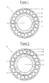
- Figure 1 is a shaft bearing 3 in the manner of a ball roller bearing illustrated, wherein the invention is not on roller bearings is limited, but rather all possible shaft bearings, such as. Roller, roller or sliding bearings and the like., Applies.
- the shaft bearing of Figure 1 has an outer shell 4, an inner shell 5, an inner side of the inner shell 5 arranged Radialverstelltechnik 1 and between the outer shell 4 and the Inner shell 5 rollable arranged balls 6.
- the Radialverstelltechnik 1 is formed by two half-shells Piezo elements formed.
- the half-shell piezo elements the Radialverstelltechnik 1 are spaced from each other the inside of the inner shell 5 arranged so that they are at rest in particular free of play on the outer surface of the rotating part 2 abut.
- the half-shell piezo elements of Radialverstelltechnik 1 be contacted in a favorable manner by electrically that to the shaft to ground and the inner shell 5 of the shaft bearing. 3 the opposite, preferably positive potential applied becomes.
- the entire shaft bearing 3 is the positive Potential applied, the shaft bearing 3 against his receiving component 7 and its other environment electrically should be isolated.
- the Radialverstellmaschine 1 can, for example, a possibly occurring Game be balanced.
- the half-shell piezo elements of Radialverstelltechnik 1 at a vibration occurring in the rotary member 2 by applying an alternating voltage to a secondary oscillation be excited.
- the secondary oscillation can with the occurring vibration, in particular a natural vibration of the Rotary part 2 are interfered, whereby the occurring Vibration is changed and especially damped.
- the secondary oscillation is expediently dependent changed by the occurring vibration. For this it makes sense to absorb the occurring vibration by means of a mathematical algorithm - for example, a Fourier transform - to analyze and thereby with suitably generated data sets the half-shell piezo elements of Radialverstelltechnik 1 to excite to a corresponding secondary oscillation.
- the vibrations occurring to determine and the records for the secondary oscillation select according to the determined vibration.
- the rotary part 2 is a rotating rotary part, in particular about a cam and / or crankshaft of an internal combustion engine, does it make sense the clamping conditions and / or the secondary vibrations depending in particular the speed and / or the crankshaft or camshaft angle of Change combustion engine.
- the offset voltage controls the radial extent or the radial Contact pressure of the half-shell piezo elements of Radialverstelltechnik 1, while the AC voltage is the piezo elements the Radialverstelltechnik 1 to the secondary vibration excited.
- the half-shell piezo elements of Radialverstelltechnik 1 a secondary oscillation, whose zero point is arranged at the one place by the offset voltage is fixed.
- an internally and externally clamped shaft bearing 3 may be a piezoelectric element of Radialverstelltechnik 1 only slightly expand physically so that it in this case, in the case of the secondary vibrations, to pressure oscillations, So it is radial force flows, which on the Rotary part 2 are transmitted. This will also the Clamping ratios of the rotating part 2 changed.
- clamping conditions and / or the secondary vibrations in a special way also depending from the temperature of the rotary part 2 and / or the shaft bearing 3rd to be changed.
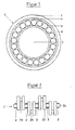
- FIG. 3 shows a further shaft bearing 3.
- this Shaft bearing 3 is the Radialverstelliser 1 on the outer surface the outer shell 4 is arranged and has an annular Piezoelement, which optionally also has an axially extending joint (not shown) may have.
- the shaft bearing 3 is arranged on the rotary member 2 such that its axis of symmetry equiaxial to the axis of rotation of the Rotary part 2 runs. Furthermore, the shaft bearing 3 supported on its two outer surfaces; i.e. the inside of the Inner shell 5 is located on the outer surface of the rotary member 2 and the Ring outside of the piezoelectric elements of Radialverstelltechnik. 1 on a part 7 at least partially surrounding it.
- the outer surface of the Outer shell 4 facing inner ring side of the piezoelectric element of Radialverstelltechnik 1 to ground and the ring outside of the Piezoelectric element of Radialverstelltechnik 1 to the positive potential placed.
- FIG 4 is arranged as a rotary member 2, a crankshaft with it Shaft bearings shown.
- the crankshaft has two axially outer side arranged main journal 21.
- a Main journals 21 follow in the direction of the axis of rotation two Crank cheeks 22, between which a bearing pin 23 is arranged is.
- the second crank arm 22 below is a Pleullagerzapfen 24 arranged, which is radial to the axis of rotation of the crankshaft is offset.
- the shaft bearings 3 according to the invention are to the Main bearing pin 21 and arranged on the bearing pin 23.
- the shaft bearings 3 are separated from each other controllable, whereby the variation possibilities of a increases the shaft bearing taking effect on the rotary member are.
- these piezo-elements used as plain bearings and at the same time as Radialverstelltechnik 1 may have a sliding layer on its surface facing the shaft.
- the sliding layer in turn, conveniently contains a dry lubricant, preferably molybdenum sulphide (MoS 2 ) and more preferably boric acid (H 3 BO 3 ).
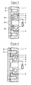
- FIG. 5 shows an end-side receptacle of a rotary part 2 in FIG a surrounding component 7 shown.
- the rotary member 2 has a stop on which the radius changes abruptly.
- the stop of the rotary member is located directly on the inner ring 5 of the Shaft bearing and is characterized in the axial direction play in the Shaft bearing arranged.
- the shaft bearing has an outer shell 4, an inner shell 5, and between the outer shell. 4 and the inner shell 5 rollably arranged balls 6.
- the inner shell 5 and the outer shell 4 each have only one transverse to its axis of rotation bearing or sliding surface for the balls 6 on.
- the inner shell 5 relative to the outer shell 6 to some extent axially displaceable.
- the material of the piezo elements of Axialverstelltechnik 1 is in this case chosen so that the axial extent of the Piezo elements increases when an electrical voltage is applied.
- the lock ring 10 is stronger in the direction of the outer shell 4 pressed and transmitted a corresponding force.
- the force on the balls 6 on the inner shell 5 and thereof transferred to the stop of the rotary member 2.
- the piezoelectric elements of the Axialverstelltechnik 1 at a vibration occurring in the rotating part 2 by applying an AC voltage to a secondary vibration excited become.
- the secondary vibration is about the power flow conductive components transmitted to the rotary member 2 and with the occurring vibration of the rotating part, in particular a natural vibration of the rotating part 2, interferes. By the interference with the secondary oscillation occurring at the rotating part Vibration changed and especially damped.
- the secondary oscillation is expediently dependent changed by the occurring vibration. For this it makes sense to absorb the occurring vibration by means of a mathematical algorithm - for example, a Fourier transform - to analyze and thereby with correspondingly generated data sets the half-shell piezo elements of Axialverstelltechnik 1 to excite to a corresponding secondary oscillation.
- FIG. 6 shows a further exemplary embodiment of an end face Receiving a rotating part 2 in a surrounding component 7 shown.
- the shaft bearing present here corresponds to that of Figure 5.
- the rotary member 2 has a stop on the radius changes abruptly.
- the stop of the rotating part is directly on the inner ring 5 of the shaft bearing and is thereby arranged in the axial direction without play in the shaft bearing.
- the material of the piezo elements is the Axialverstelltechnik 1 in this case chosen so that the axial extent of the Piezo elements reduced when applying an electrical voltage, whereby the biased with screws 9 the Press cover plate 8 more strongly in the direction of the rotating part.
- This Force is transmitted to the outer shell 4 via the dome. From the outer shell 4 is the force on the balls 6 on the inner shell 5 and transferred to the stop of the rotating part.
- This acting in the axial direction of power flow is axial clamping ratio of the rotating part changed and the resonance frequency of the rotary part detuned, so that the here Transfer function specifically reduced noise minimizing becomes.
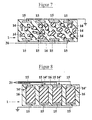
- FIG. 7 shows a seal of an axial or radial adjustment unit 1 with a matrix 16 of preferably electrically conductive Plastic, in the plurality of piezo elements 14 in any Size, orientation and physical design embedded are.
- a matrix 16 of preferably electrically conductive Plastic in the plurality of piezo elements 14 in any Size, orientation and physical design embedded are.
- Such an arrangement is i.a. as 0-3 piezoceramic polymer composite designated.
- electrical contacts 15 In the area of the wall of the seal are conveniently arranged electrical contacts 15, by electrical control lines 20 with a control unit (not shown) are connected.
- the individual piezo elements 14 are targeted to one and the other is it possible to tap an electrical voltage that e.g. can arise, transmitted from a rotary member 2 Vibrations exert a pressure on the piezoelectric elements 14 and deform them.
- FIG. 8 shows another active seal of an axial or Radialverstelltechnik 1 shown with a plastic matrix 16, in which a plurality of piezo elements 14 'are embedded. in the Contrary to the embodiment of Figure 7, these are Piezo elements 14 'of a certain size and shape and in addition oriented arranged. Such an arrangement is i.a. as 1-3 piezoceramic polymer composite referred to.
- the piezo elements 14 'of the seal of an axial or Radialverstelltechnik 1 are preferably formed in the manner of Piezostaks and / or lamellar and in particular aligned one behind the other arranged in the seal.
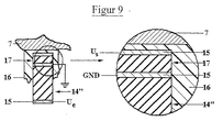
- FIG. 9 shows an active seal of an axial or radial adjustment unit 1 shown with a plastic matrix 16, in the plurality of piezo elements 14 '' with associated piezoelectric Sensors 17 are embedded.
- the piezo elements 14 '' same in terms of design and oriented arrangement largely those of Figure 8.
- the sensor 17 has a common and an additional electrical Contact 15 on.
- the common contact 15, between the Piezo element 14 '' and the sensor 17 is arranged, is expediently grounded or to a zero electrical potential placed.
- the individual piezo elements 14 '' targeted to secondary vibrations with desired Frequencies and amplitudes are excited.
- the secondary vibrations can with the transmitted from the rotary member 2 Vibrations interfere and / or these are superimposed.
- each sensor 17 and the respective piezo elements 14 '' can the determination the residual vibration and the initiation of the secondary vibration done with a good resolution and flexibility.
Landscapes
- Engineering & Computer Science (AREA)
- General Engineering & Computer Science (AREA)
- Mechanical Engineering (AREA)
- Shafts, Cranks, Connecting Bars, And Related Bearings (AREA)
- Support Of The Bearing (AREA)
- Rolling Contact Bearings (AREA)
- Vibration Prevention Devices (AREA)
Claims (11)
- Procédé pour modifier la précharge d'un membre rotatif, lequel est logé de façon rotative dans le palier d'arbre, et dans lequel l'axe de rotation du membre rotatif est disposé dans le même axe par rapport à l'axe de rotation du palier d'arbre, caractérisé en ce que,la précharge axiale et radiale entre le palier d'arbre (3) et un membre rotatif (2), en particulier un arbre, de la machine, maintenu de façon rotative dans le palier d'arbre (3), est modifiée au moyen d'une unité de réglage axial (31) et d'une unité de réglage radial (1) ou d'une unité combinée de réglage axial et radial (14, 14', 14''),la précharge entre le membre rotatif (2) et le palier d'arbre (3) étant modifiée de manière commandée,la précharge entre le membre rotatif (2) eL le palier d'arbre (3) étant modifiée en fonction des vibrations apparaissant sur le membre rotatif (2),en modifiant la précharge, la fonction de transfert des vibrations, en particulier des vibrations produisant des ondes sonores, présente entre le membre rotatif (2) et le palier d'arbre (3) ou un des composants (7) en contact avec le palier d'arbre, est modifiée.
- Procédé selon la revendication 1, caractérisé en ce que pour modifier la précharge, l'extension radiale d'une unité de réglage radial (1) comprenant un matériau piézoélectriquement actif et d'une unité de réglage axial (31) comprenant un matériau piézoélectriquement actif peut être modifiée de façon réversible.
- Procédé selon la revendication 1, caractérisé en ce que la précharge est modifiée en fonction d'un paramètre de la machine, en particulier du régime et/ou de l'angle du vilebrequin d'un moteur à combustion interne.
- Procédé selon la revendication 1, caractérisé en ce que les données permettant de commander la précharge sont prélevées d'un enregistrement placé dans une mémoire d'informations.
- Membre rotatif, qui est logé de façon rotative dans un palier d'arbre et dont l'axe de rotation est disposé dans le même axe par rapport à l'axe de rotation ou de symétrie du palier d'arbre, et comprenant une unité de réglage permettant de compenser un jeu du membre rotatif, caractérisé en ce que l'unité de réglage comprend une unité de réglage radial (1) et une unité de réglage axial (31), en ce que l'unité de réglage radial (1) comprend un matériau piézoélectriquement actif, en ce que grâce à l'unité de réglage radial (1) l'extension radiale effective au niveau du membre rotatif (2) à maintenir et/ou la pression d'appui sur le membre rotatif (2) peut être modifiée au moins entre deux dimensions de façon réversible et commandée, en ce que l'unité de réglage axial (31) comprend un matériau piézoélectriquement actif, et en ce que grâce à l'unité de réglage axial (31), l'extension axiale effective au niveau du membre rotatif (2) à maintenir et/ou la pression d'appui axiale sur le membre rotatif (2) peut être modifiée entre deux dimensions de façon réversible et commandée.
- Membre rotatif selon la revendication 5, caractérisé en ce que l'unité de réglage radial (1) est disposée directement sur le périmètre extérieur du membre rotatif (2).
- Membre rotatif selon la revendication 5, caractérisé en ce que l'unité de réglage radial (1) est disposée sur le périmètre extérieur du palier d'arbre (3).
- Membre rotatif selon la revendication 5, caractérisé en ce que l'unité de réglage radial (1) est conçue sous la forme d'une coque séparée en deux.
- Membre rotatif selon la revendication 5, caractérisé en ce que le membre rotatif (2) est un membre d'un système rotatif, de préférence un vilebrequin ou un arbre à cames d'un moteur à combustion interne, en particulier d'un moteur diesel ou essence.
- Membre rotatif selon la revendication 5, caractérisé en ce que le membre rotatif (2) est un membre d'un système rotatif, de préférence un arbre ou un rotateur d'un électromoteur.
- Membre rotatif selon la revendication 5, caractérisé en ce que le membre rotatif (2) est un membre d'un système rotatif d'une hélice ou d'une propulsion à réaction.
Applications Claiming Priority (2)
| Application Number | Priority Date | Filing Date | Title |
|---|---|---|---|
| DE19826174 | 1998-06-13 | ||
| DE19826174A DE19826174C2 (de) | 1998-06-13 | 1998-06-13 | Verfahren zur Veränderung der Einspannverhältnisse einer Welle |
Publications (2)
| Publication Number | Publication Date |
|---|---|
| EP0964172A1 EP0964172A1 (fr) | 1999-12-15 |
| EP0964172B1 true EP0964172B1 (fr) | 2004-03-10 |
Family
ID=7870675
Family Applications (1)
| Application Number | Title | Priority Date | Filing Date |
|---|---|---|---|
| EP99110821A Expired - Lifetime EP0964172B1 (fr) | 1998-06-13 | 1999-06-05 | Méthode pour modifier la précharge d'un membre rotatif et membre rotatif |
Country Status (3)
| Country | Link |
|---|---|
| US (1) | US6283636B1 (fr) |
| EP (1) | EP0964172B1 (fr) |
| DE (1) | DE19826174C2 (fr) |
Cited By (1)
| Publication number | Priority date | Publication date | Assignee | Title |
|---|---|---|---|---|
| DE102008052261A1 (de) * | 2008-10-18 | 2010-04-22 | Bosch Mahle Turbo Systems Gmbh & Co. Kg | Abgasturbolader |
Families Citing this family (10)
| Publication number | Priority date | Publication date | Assignee | Title |
|---|---|---|---|---|
| DE20011948U1 (de) | 2000-07-10 | 2000-12-07 | Skf Gmbh, 97421 Schweinfurt | Lageranordnung |
| DE10110822B4 (de) * | 2001-03-07 | 2006-06-01 | Daimlerchrysler Ag | Verfahren und Vorrichtung zur Beeinflussung der Übertragung von Schwingungen eines Schwingungserzeugers an einen damit verbundenen Gegenstand, insbesondere von Motorschwingungen auf die Karosserie eines Kraftfahrzeuges |
| DE10235287A1 (de) * | 2002-08-02 | 2004-02-12 | Ab Skf | Lageranordnung |
| DE102004024851A1 (de) * | 2004-05-19 | 2005-12-22 | Fag Kugelfischer Ag & Co. Ohg | Lageranordnung zur Lagerung wenigstens eines Maschinenteiles |
| DE102005007985A1 (de) | 2005-02-22 | 2006-08-31 | Schaeffler Kg | Verfahren und Vorrichtung zur Schwingungsdämpfung |
| US8002251B2 (en) | 2007-11-14 | 2011-08-23 | Honeywell International Inc. | Vibration reduction system employing active bearing mounts |
| DE102008004565A1 (de) | 2008-01-15 | 2009-07-23 | Ab Skf | Aktiv gedämpfter Lageranordnung |
| DE102009024291A1 (de) * | 2009-06-05 | 2010-12-09 | Gottfried Wilhelm Leibniz Universität Hannover | Drehlager und Feinbearbeitungsverfahren |
| DE102010019677A1 (de) * | 2009-09-24 | 2011-09-29 | Jens Mehnert | Verfahren und Vorrichtung zur Konditionierung von Lagersystemen für Wellen |
| DE102013210692A1 (de) * | 2013-06-07 | 2014-12-11 | Schaeffler Technologies Gmbh & Co. Kg | Aktive Lagervorrichtung |
Family Cites Families (17)
| Publication number | Priority date | Publication date | Assignee | Title |
|---|---|---|---|---|
| DE3123590A1 (de) * | 1981-06-13 | 1983-01-05 | Lemförder Metallwaren AG, 2844 Lemförde | "kugelgelenk" |
| JPS61127922A (ja) * | 1984-11-27 | 1986-06-16 | Okuma Mach Works Ltd | ころがり軸受用自動予圧調整装置 |
| US4657412A (en) * | 1985-03-25 | 1987-04-14 | The Torrington Company | Variable preload bearing assembly |
| DE3810448A1 (de) * | 1987-04-11 | 1988-10-20 | Zahnradfabrik Friedrichshafen | Ausgleichseinrichtung fuer ein waelzlager |
| GB2223544B (en) * | 1988-03-14 | 1993-04-07 | Okuma Machinery Works Ltd | Feed-screw support structure |
| DE3900121A1 (de) * | 1989-01-04 | 1990-07-19 | Inst Produktionstechnik Karlsr | Vorrichtung zur einstellung der axialen vorspannung von waelzlagern und spindelmuttern |
| JPH01266320A (ja) * | 1988-04-19 | 1989-10-24 | Nippon Seiko Kk | 転がり軸受の予圧装置 |
| US4850719A (en) * | 1988-09-12 | 1989-07-25 | The Torrington Company | Bearing with adjustable stiffness |
| JP2794683B2 (ja) * | 1991-04-16 | 1998-09-10 | 日産自動車株式会社 | 歯車支持軸受構造 |
| DE4227366A1 (de) * | 1992-08-19 | 1994-02-24 | Schaeffler Waelzlager Kg | Lagerung mit Dämpfung |
| JP3345930B2 (ja) * | 1993-01-06 | 2002-11-18 | 日産自動車株式会社 | アクティブコントロール装置 |
| DE9301334U1 (de) * | 1993-02-01 | 1993-04-01 | Ing. Lang & Menke Gmbh, 5870 Hemer | Federscheibe zum Spielausgleich bei Kugellagern |
| US5332061A (en) * | 1993-03-12 | 1994-07-26 | General Motors Corporation | Active vibration control system for attenuating engine generated vibrations in a vehicle |
| JP3604431B2 (ja) * | 1994-12-13 | 2004-12-22 | 光洋精工株式会社 | 転がり軸受の予圧付与装置 |
| DE19531402C2 (de) * | 1995-08-26 | 1999-04-01 | Mannesmann Sachs Ag | Vorrichtung und Verfahren zum Beeinflussen von Schwingungen in einem Fahrgastraum eines Kraftfahrzeugs und Vorrichtung und Verfahren zum Erkennen von Defekten an einem Kraftfahrzeug |
| DE19541245A1 (de) * | 1995-11-06 | 1997-05-07 | Klein Schanzlin & Becker Ag | Gleitlagerung für eine Maschinenwelle |
| US5564840A (en) * | 1996-01-02 | 1996-10-15 | The Torrington Company | Preload adjustment apparatus and method |
-
1998
- 1998-06-13 DE DE19826174A patent/DE19826174C2/de not_active Expired - Fee Related
-
1999
- 1999-06-05 EP EP99110821A patent/EP0964172B1/fr not_active Expired - Lifetime
- 1999-06-10 US US09/329,789 patent/US6283636B1/en not_active Expired - Lifetime
Cited By (1)
| Publication number | Priority date | Publication date | Assignee | Title |
|---|---|---|---|---|
| DE102008052261A1 (de) * | 2008-10-18 | 2010-04-22 | Bosch Mahle Turbo Systems Gmbh & Co. Kg | Abgasturbolader |
Also Published As
| Publication number | Publication date |
|---|---|
| DE19826174A1 (de) | 1999-12-16 |
| DE19826174C2 (de) | 2002-02-21 |
| US6283636B1 (en) | 2001-09-04 |
| EP0964172A1 (fr) | 1999-12-15 |
Similar Documents
| Publication | Publication Date | Title |
|---|---|---|
| EP0964182B1 (fr) | Méthode et dispositif pour influencer une barrière au bruit d'une pièce rotative d'une machine | |
| EP0347666B1 (fr) | Agencement de support pour amortir et compenser les oscillations | |
| EP0964172B1 (fr) | Méthode pour modifier la précharge d'un membre rotatif et membre rotatif | |
| DE69814417T2 (de) | Endkappe für einen ultra-lärmarmen elektrischen Motor | |
| EP0964174A2 (fr) | Méthode pour dérégler la fréquence propre d'un membre rotatif ainsi que membre rotatif règlable | |
| DE19826172C2 (de) | Verfahren zur Veränderung der Einspannverhältnisse zwischen einem Wellenlager und einem Drehteil sowie Wellenlager | |
| EP1239183A2 (fr) | Procédure et dispositif pour influencer la transmission de vibrations d'un élément vibratoire à une unité liée avec, en particulier les vibrations d'un moteur à la carosserie d'un véhicule | |
| DE3902605A1 (de) | Elastische lagerung, insbesondere kraftfahrzeug-motorlager | |
| DE3902603C2 (de) | Elastische Lagerung, insbesondere Kraftfahrzeug-Motorlager | |
| DE102013100964A1 (de) | Verfahren zum aktiven Dämpfen von Drehschwingungen einer Welle einer Maschine, insbesondere einer Kurbelwelle einer Hubkolbenmaschine, und eine entsprechende Anordnung zur Durchführung des Verfahrens | |
| DE102016201099A1 (de) | Fliehkraftpendel | |
| DE69321742T2 (de) | Vibrationsgetriebener Antrieb | |
| DE19502030C1 (de) | Schalldämmeinrichtung und Verfahren zur Dämmung von Körperschall | |
| DE10312786A1 (de) | Zweimassenschwungrad mit zwei in Reihe geschalteten Torsionsdämpfern | |
| WO2015176797A1 (fr) | Amortisseur de rotation | |
| EP4015271A1 (fr) | Palier élastique | |
| DE102010020032A1 (de) | Schwingungstilger | |
| AT527221B1 (de) | Getriebe mit Geräuschreduzierung | |
| WO2005047729A1 (fr) | Dispositif pour amortir des vibrations | |
| EP1797340B1 (fr) | Dispositif de connexion | |
| DE102014220494A1 (de) | Rotorträger für Hybridmodul | |
| DE102013100965B4 (de) | Verfahren zum aktiven Isolieren eines Antriebsstrangs von Drehschwingungen einer Welle einer Maschine, insbesondere einer Kurbelwelle einer Hubkolbenmaschine, und eine entsprechende Anordnung zur Durchführung des Verfahrens | |
| DE19826526B4 (de) | Anordnung zur Funktionsprüfung von Abtriebsstrangkomponenten durch einen rotierenden Antrieb | |
| WO2001065094A1 (fr) | Vilebrequin a attenuation elevee des oscillations | |
| DE102021204376A1 (de) | Elektronisch kommutierte Maschine und elektronisch schlupfregelbare Fremdkraftbremsanlage mit einer elektronisch kommutierten Maschine |
Legal Events
| Date | Code | Title | Description |
|---|---|---|---|
| PUAI | Public reference made under article 153(3) epc to a published international application that has entered the european phase |
Free format text: ORIGINAL CODE: 0009012 |
|
| AK | Designated contracting states |
Kind code of ref document: A1 Designated state(s): ES FR GB IT |
|
| AX | Request for extension of the european patent |
Free format text: AL;LT;LV;MK;RO;SI |
|
| 17P | Request for examination filed |
Effective date: 19991124 |
|
| AKX | Designation fees paid |
Free format text: ES FR GB IT |
|
| REG | Reference to a national code |
Ref country code: DE Ref legal event code: 8566 |
|
| REG | Reference to a national code |
Ref country code: GB Ref legal event code: FG4D Free format text: NOT ENGLISH |
|
| GRAP | Despatch of communication of intention to grant a patent |
Free format text: ORIGINAL CODE: EPIDOSNIGR1 |
|
| GRAS | Grant fee paid |
Free format text: ORIGINAL CODE: EPIDOSNIGR3 |
|
| GRAA | (expected) grant |
Free format text: ORIGINAL CODE: 0009210 |
|
| RIN1 | Information on inventor provided before grant (corrected) |
Inventor name: TOMASCHKO, SILVIA DR. Inventor name: SCHNUR, JUERGEN |
|
| AK | Designated contracting states |
Kind code of ref document: B1 Designated state(s): ES FR GB IT |
|
| PG25 | Lapsed in a contracting state [announced via postgrant information from national office to epo] |
Ref country code: ES Free format text: LAPSE BECAUSE OF FAILURE TO SUBMIT A TRANSLATION OF THE DESCRIPTION OR TO PAY THE FEE WITHIN THE PRESCRIBED TIME-LIMIT Effective date: 20040621 |
|
| GBT | Gb: translation of ep patent filed (gb section 77(6)(a)/1977) |
Effective date: 20040602 |
|
| ET | Fr: translation filed | ||
| PLBE | No opposition filed within time limit |
Free format text: ORIGINAL CODE: 0009261 |
|
| STAA | Information on the status of an ep patent application or granted ep patent |
Free format text: STATUS: NO OPPOSITION FILED WITHIN TIME LIMIT |
|
| 26N | No opposition filed |
Effective date: 20041213 |
|
| PGFP | Annual fee paid to national office [announced via postgrant information from national office to epo] |
Ref country code: GB Payment date: 20050525 Year of fee payment: 7 |
|
| PGFP | Annual fee paid to national office [announced via postgrant information from national office to epo] |
Ref country code: FR Payment date: 20050610 Year of fee payment: 7 |
|
| PG25 | Lapsed in a contracting state [announced via postgrant information from national office to epo] |
Ref country code: GB Free format text: LAPSE BECAUSE OF NON-PAYMENT OF DUE FEES Effective date: 20060605 |
|
| PGFP | Annual fee paid to national office [announced via postgrant information from national office to epo] |
Ref country code: IT Payment date: 20060630 Year of fee payment: 8 |
|
| GBPC | Gb: european patent ceased through non-payment of renewal fee |
Effective date: 20060605 |
|
| REG | Reference to a national code |
Ref country code: FR Ref legal event code: ST Effective date: 20070228 |
|
| PG25 | Lapsed in a contracting state [announced via postgrant information from national office to epo] |
Ref country code: FR Free format text: LAPSE BECAUSE OF NON-PAYMENT OF DUE FEES Effective date: 20060630 |
|
| PG25 | Lapsed in a contracting state [announced via postgrant information from national office to epo] |
Ref country code: IT Free format text: LAPSE BECAUSE OF NON-PAYMENT OF DUE FEES Effective date: 20070605 |