EP0964182A2 - Verfahren und Vorrichtung zur Beeinflussung einer Geräuschkulisse einer rotierende Teile aufweisenden Maschine - Google Patents
Verfahren und Vorrichtung zur Beeinflussung einer Geräuschkulisse einer rotierende Teile aufweisenden Maschine Download PDFInfo
- Publication number
- EP0964182A2 EP0964182A2 EP99110826A EP99110826A EP0964182A2 EP 0964182 A2 EP0964182 A2 EP 0964182A2 EP 99110826 A EP99110826 A EP 99110826A EP 99110826 A EP99110826 A EP 99110826A EP 0964182 A2 EP0964182 A2 EP 0964182A2
- Authority
- EP
- European Patent Office
- Prior art keywords
- shaft bearing
- rotating part
- adjustment unit
- vibrations
- radial adjustment
- Prior art date
- Legal status (The legal status is an assumption and is not a legal conclusion. Google has not performed a legal analysis and makes no representation as to the accuracy of the status listed.)
- Granted
Links
- 238000000034 method Methods 0.000 title claims abstract description 16
- 230000004888 barrier function Effects 0.000 title 1
- 238000012546 transfer Methods 0.000 claims abstract description 5
- 230000008859 change Effects 0.000 claims description 12
- 238000002485 combustion reaction Methods 0.000 claims description 8
- 230000006870 function Effects 0.000 claims description 6
- 239000011149 active material Substances 0.000 claims 2
- 230000005540 biological transmission Effects 0.000 description 8
- 239000011159 matrix material Substances 0.000 description 8
- 230000001419 dependent effect Effects 0.000 description 5
- 230000000875 corresponding effect Effects 0.000 description 4
- 238000013461 design Methods 0.000 description 3
- 239000010410 layer Substances 0.000 description 3
- 229920000642 polymer Polymers 0.000 description 3
- 239000002131 composite material Substances 0.000 description 2
- 238000010276 construction Methods 0.000 description 2
- 230000003292 diminished effect Effects 0.000 description 2
- 230000000977 initiatory effect Effects 0.000 description 2
- 239000012791 sliding layer Substances 0.000 description 2
- UCKMPCXJQFINFW-UHFFFAOYSA-N Sulphide Chemical compound [S-2] UCKMPCXJQFINFW-UHFFFAOYSA-N 0.000 description 1
- KGBXLFKZBHKPEV-UHFFFAOYSA-N boric acid Chemical compound OB(O)O KGBXLFKZBHKPEV-UHFFFAOYSA-N 0.000 description 1
- 230000002596 correlated effect Effects 0.000 description 1
- 238000013500 data storage Methods 0.000 description 1
- 238000011161 development Methods 0.000 description 1
- 230000000694 effects Effects 0.000 description 1
- 229920001971 elastomer Polymers 0.000 description 1
- 239000000806 elastomer Substances 0.000 description 1
- 238000011156 evaluation Methods 0.000 description 1
- 230000005284 excitation Effects 0.000 description 1
- 230000002349 favourable effect Effects 0.000 description 1
- 230000006872 improvement Effects 0.000 description 1
- 239000000314 lubricant Substances 0.000 description 1
- 238000004519 manufacturing process Methods 0.000 description 1
- 239000012528 membrane Substances 0.000 description 1
- 230000008447 perception Effects 0.000 description 1
- 230000008569 process Effects 0.000 description 1
- 230000001681 protective effect Effects 0.000 description 1
- 230000002441 reversible effect Effects 0.000 description 1
- 238000007789 sealing Methods 0.000 description 1
- 230000010360 secondary oscillation Effects 0.000 description 1
- 230000035807 sensation Effects 0.000 description 1
- 239000007787 solid Substances 0.000 description 1
- 230000009466 transformation Effects 0.000 description 1
Images


Classifications
-
- F—MECHANICAL ENGINEERING; LIGHTING; HEATING; WEAPONS; BLASTING
- F16—ENGINEERING ELEMENTS AND UNITS; GENERAL MEASURES FOR PRODUCING AND MAINTAINING EFFECTIVE FUNCTIONING OF MACHINES OR INSTALLATIONS; THERMAL INSULATION IN GENERAL
- F16C—SHAFTS; FLEXIBLE SHAFTS; ELEMENTS OR CRANKSHAFT MECHANISMS; ROTARY BODIES OTHER THAN GEARING ELEMENTS; BEARINGS
- F16C27/00—Elastic or yielding bearings or bearing supports, for exclusively rotary movement
- F16C27/04—Ball or roller bearings, e.g. with resilient rolling bodies
-
- F—MECHANICAL ENGINEERING; LIGHTING; HEATING; WEAPONS; BLASTING
- F02—COMBUSTION ENGINES; HOT-GAS OR COMBUSTION-PRODUCT ENGINE PLANTS
- F02F—CYLINDERS, PISTONS OR CASINGS, FOR COMBUSTION ENGINES; ARRANGEMENTS OF SEALINGS IN COMBUSTION ENGINES
- F02F7/00—Casings, e.g. crankcases
- F02F7/0065—Shape of casings for other machine parts and purposes, e.g. utilisation purposes, safety
- F02F7/008—Sound insulation
-
- F—MECHANICAL ENGINEERING; LIGHTING; HEATING; WEAPONS; BLASTING
- F16—ENGINEERING ELEMENTS AND UNITS; GENERAL MEASURES FOR PRODUCING AND MAINTAINING EFFECTIVE FUNCTIONING OF MACHINES OR INSTALLATIONS; THERMAL INSULATION IN GENERAL
- F16C—SHAFTS; FLEXIBLE SHAFTS; ELEMENTS OR CRANKSHAFT MECHANISMS; ROTARY BODIES OTHER THAN GEARING ELEMENTS; BEARINGS
- F16C19/00—Bearings with rolling contact, for exclusively rotary movement
- F16C19/52—Bearings with rolling contact, for exclusively rotary movement with devices affected by abnormal or undesired conditions
- F16C19/527—Bearings with rolling contact, for exclusively rotary movement with devices affected by abnormal or undesired conditions related to vibration and noise
-
- F—MECHANICAL ENGINEERING; LIGHTING; HEATING; WEAPONS; BLASTING
- F16—ENGINEERING ELEMENTS AND UNITS; GENERAL MEASURES FOR PRODUCING AND MAINTAINING EFFECTIVE FUNCTIONING OF MACHINES OR INSTALLATIONS; THERMAL INSULATION IN GENERAL
- F16F—SPRINGS; SHOCK-ABSORBERS; MEANS FOR DAMPING VIBRATION
- F16F15/00—Suppression of vibrations in systems; Means or arrangements for avoiding or reducing out-of-balance forces, e.g. due to motion
- F16F15/005—Suppression of vibrations in systems; Means or arrangements for avoiding or reducing out-of-balance forces, e.g. due to motion using electro- or magnetostrictive actuation means
-
- F—MECHANICAL ENGINEERING; LIGHTING; HEATING; WEAPONS; BLASTING
- F16—ENGINEERING ELEMENTS AND UNITS; GENERAL MEASURES FOR PRODUCING AND MAINTAINING EFFECTIVE FUNCTIONING OF MACHINES OR INSTALLATIONS; THERMAL INSULATION IN GENERAL
- F16C—SHAFTS; FLEXIBLE SHAFTS; ELEMENTS OR CRANKSHAFT MECHANISMS; ROTARY BODIES OTHER THAN GEARING ELEMENTS; BEARINGS
- F16C19/00—Bearings with rolling contact, for exclusively rotary movement
- F16C19/02—Bearings with rolling contact, for exclusively rotary movement with bearing balls essentially of the same size in one or more circular rows
- F16C19/04—Bearings with rolling contact, for exclusively rotary movement with bearing balls essentially of the same size in one or more circular rows for radial load mainly
- F16C19/06—Bearings with rolling contact, for exclusively rotary movement with bearing balls essentially of the same size in one or more circular rows for radial load mainly with a single row or balls
Definitions
- the invention relates to a method for influencing a Background noise of a machine, what background noise at least starts from a rotating part of the machine, in particular to influence the background noise within a Passenger cell of a motor vehicle, in which method the Amplitudes and / or the frequencies of primary vibrations that the background noise caused by targeted external interventions changed, preferably reduced and / or supplemented, and a shaft bearing for receiving an inside of the shaft bearing rotatably supported rotating part, in particular a shaft, wherein the axis of rotation of the rotating part coaxially with the axis of rotation of the bearing is arranged, and with a radial adjustment unit to change the clamping conditions of the Turned part in or on the shaft bearing according to the generic terms of claims 1 and 5, respectively.
- Machines with rotating parts usually have at least one certain disturbing background noise.
- One reason for this noise lies among other things remember that the rotating parts, in particular Introduce waves, vibrations into other components.
- vibrations For the transmission of vibrations between components or for Introduction of vibrations from one component to another Component resonance frequencies are important.
- This frequency-dependent transmission becomes a transmission function called.
- No. 5,332,061 A1 describes methods for suppressing in the body initiated vibrations and a corresponding Vehicle known.
- the vibrations introduced among others also lead to audible vibrations, come from the engine and are located at the connection points of the engine transferred with the body.
- the vehicle has shakers, i.e. mechanical vibration exciters on that in the area of at least some connection points of the engine are arranged with the body.
- the shakers are dependent on the Motor speed at the resonance frequencies in phase opposition to the Vibrations coming from the engine are excited, causing transmission the vibrations introduced are at least dampened.
- the corresponding frequencies and their amplitudes for the secondary vibrations are a previously stored data field taken.
- the object is achieved according to the invention with a method according to claim 1 and solved with a shaft bearing according to claim 5.
- a radial adjustment unit having in particular piezo elements or the one acting radially on the rotating part Contact pressure, the clamping conditions during operation can be changed through targeted intervention from outside.
- the change in the clamping conditions causes, for example, that the values of the natural vibrations of the turned part and also the transfer function changed from the turned part to another component become.
- the transfer function By changing the transfer function, the Transmission of vibrations, i.e. the transferable energy, that come from the turned part, changed into another component, especially at least diminished.
- the intervention takes place through the Applying an electrical voltage.
- This measure leads to a change in the resonance or natural frequencies of the turned part and also a change in transmission or initiation of vibrations.
- Resonance frequencies important.
- the mathematical context of this frequency-dependent energy or vibration transmission is called the transfer function.
- a game that changes due to temperature influences while operation of the turned part. This is useful, for example. for a game compensation.
- the invention is also used in a Crankshaft and / or camshaft of an internal combustion engine, preferably of a diesel or petrol engine as a turned part, since the vibrations introduced here are then simple and in particular the noise emission within affects a passenger compartment of an internal combustion engine powered vehicle can be.
- the influencing takes place here preferably which is particularly disruptive by the operator of a vehicle perceptible and at least partly coming from the engine Noise level at the point of origin and not as usual, only at the point of perception by the operator.
- Control electronics and equipment microphone, loudspeaker and the like.
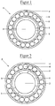
- FIG. 1 is a shaft bearing 3 in the manner of a ball roller bearing shown, the invention not on roller bearings is limited, but rather all possible shaft bearings, such as roller, roller or slide bearings and the like.
- the shaft bearing according to FIG. 1 has an outer shell 4, an inner shell 5, a radial adjustment unit arranged on the inside of the inner shell 5 1 and between the outer shell 4 and the Inner shell 5 balls 6 arranged on rollers.
- the radial adjustment unit 1 is formed by two half-shells Piezo elements formed.
- the half-shell piezo elements the radial adjustment unit 1 are spaced apart from one another the inside of the inner shell 5 arranged so that it is at rest in particular without play on the outer surface of the turned part 2 concerns.
- the half-shell piezo elements of the radial adjustment unit 1 are contacted electrically in a favorable manner in that to the shaft to ground and the inner shell 5 of the shaft bearing 3 the opposite, preferably positive potential becomes.
- the positive is preferably applied to the entire shaft bearing 3 Potential applied, the shaft bearing 3 compared to its receiving component 7 and its other surroundings electrically should be isolated.
- the electrical contacting of the shaft bearing 3 can the half-shell piezo elements of the radial adjustment unit 1 stretched radially by applying an electrical direct voltage be, whereby the contact pressure on the shaft and so that the previously existing clamping conditions change.
- the radial adjustment unit 1 can, for example, also occur Game be balanced.
- the half-shell piezo elements of the radial adjustment unit 1 with a vibration occurring in the rotating part 2 by applying an AC voltage to a secondary vibration be excited.
- the secondary vibration can with the occurring vibration, in particular a natural vibration of the Rotating part 2 are interfered, causing the occurring Vibration is changed and in particular damped.
- a complex recording and / or evaluation electronics for the vibration occurring can be dispensed with in a special way when the records are used to control the clamping ratios and / or the secondary vibration, preferably an electronic one Data storage, in the previous example accordingly determined data records are stored.
- a respective data record is extracted depending on one with the operation of the rotating part 2 correlated parameters.
- the rotating part 2 is a rotating rotating part, in particular around a camshaft and / or crankshaft of an internal combustion engine, it makes sense to use the clamping conditions and / or the secondary vibrations depending in particular the speed and / or the crank or camshaft angle of the Change internal combustion engine.
- the radial adjustment of the radial adjustment unit can be sensible 1 and the artificial generation of the secondary vibration be connected together, thereby creating the device or the process according to the invention becomes more flexible.
- the combination of these two uses one Shaft bearing 3 according to the invention can be done in that as electrical voltage an alternating voltage with an additional DC voltage (a so-called offset voltage) is used becomes.
- the offset voltage regulates the radial extension or the radial one Contact pressure of the half-shell piezo elements of the radial adjustment unit 1, while the AC voltage the piezo elements the radial adjustment unit 1 is excited to the secondary vibration.
- the half-shell piezo elements of the radial adjustment unit 1 a secondary oscillation whose zero point is located at the location determined by the offset voltage is set.
- clamping conditions and / or the secondary vibrations in a special way also depending the temperature of the rotating part 2 and / or the shaft bearing 3 to be changed.
- FIG. 1 Another shaft bearing 3 is shown in FIG. With this Shaft bearing 3 is the radial adjustment unit 1 on the outer surface the outer shell 4 arranged and has an annular Piezo element on, possibly also an axially extending joint (not shown).
- the shaft bearing 3 is arranged on the rotating part 2 such that its axis of symmetry coaxial with the axis of rotation of the Turned part 2 runs. Furthermore, the shaft bearing 3 is on supported on its two outer surfaces; i.e. the inside of the Inner shell 5 lies on the outer surface of the rotating part 2 and Ring outside of the piezo elements of the radial adjustment unit 1 on a component 7 surrounding it at least in regions.
- a radial play occurs between the one surrounding the shaft bearing 3 Component 7 and / or between the shaft bearing 3 and the Rotating part 2 on, an electrical voltage is applied to the piezo element the radial adjustment unit 1.
- the radial extension changes (direct) voltage of the piezo element of the radial adjustment unit 1. This will Game at least diminished. It makes sense to use the electrical Tension selected so that the change in radial extension corresponds to the size of the game.
- the electrical voltage exhibits an AC voltage component
- crankshaft with a rotating part 2 is arranged thereon Shaft bearings shown.
- the crankshaft has two main bearing journal 21 arranged axially on the outside.
- One Main journal 21 follow two in the direction of the axis of rotation Crank cheeks 22, between which a journal 23 is arranged is.
- the second crank arm 22 is followed by a connecting rod bearing journal 24 arranged radially to the axis of rotation of the crankshaft is offset.
- another crank cheek follows 22, a bearing pin 23, a crank arm 22, a connecting rod bearing pin 23 etc.
- the shaft bearings 3 according to the invention are on the Main bearing pin 21 and arranged on the bearing pin 23. In the shaft bearings 3 are preferably separate from one another controllable, whereby the possible variations through the shaft bearing influence on the turned part increased are.
- the piezo elements can immediately form the slide bearings.
- these piezo elements used as slide bearings and at the same time as radial adjusting unit 1 can have a sliding layer on their surface facing the shaft.
- the sliding layer in turn expediently has a dry lubricant, preferably molydane sulfide (MoS 2 ) and particularly preferably boric acid (H 3 BO 3 ).
- FIG 5 is a detailed drawing of a face in one surrounding component 7 shown rotating part 2.
- the Shaft bearing 3 is at the front end area of the rotating part 2 arranged. It corresponds to the design of the shaft bearing 3 Figure 3, so that the shaft bearing 3 is no longer discussed in more detail becomes.
- the shaft bearing 3 In the area of the end face of the rotating part 2 is on the shaft bearing 3 has an annular lock ring 10, which covers the outer shell 4 and the radial adjustment unit 1.
- the counter ring 10 lies with one of its two radial surfaces both on the radial adjustment unit 1 and on the Touching outer shell 4 of the shaft bearing 3.
- On the opposite Radial surface of the counter ring 10 lies on the counter ring 10 touching an end plate 8.
- the end plate 8 is by the screws 9 with the surrounding component 7 screwed.
- This construction is the radial adjustment unit 1 and the shaft bearing 3 against the lock ring 10 against the end plate 8 in the axial direction and thus also opposite supported the surrounding component 7.
- FIG. 6 shows a seal of a radial adjustment unit 1 a matrix 16 of preferably electrically conductive plastic, in which several piezo elements 14 of any size, Orientation and physical design are embedded.
- a such an arrangement is generally as a 0-3 piezoceramic polymer composite designated.
- electrical contacts 15 through electrical control lines 20 with a control unit (not shown) are connected.
- the individual piezo elements 14 are controlled on the one hand and on the other hand it is possible to tap an electrical voltage that e.g. can arise from that transmitted by a rotating part 2 Vibrations exert a pressure on the piezo elements 14 and deform them.
- a seal can also be applied to the electrical contacts 15 are dispensed with.
- the piezo elements 14 also to an electrical voltage.
- the electrical voltage here is then heated up the plastic matrix 16 of the seal implemented, with what the system is also damped.
- FIG. 7 shows a further active seal of a radial adjustment unit 1 with a plastic matrix 16, in of which several piezo elements 14 'are embedded. In contrast to 6 are these piezo elements 14 'of a certain size and shape and additionally arranged in an oriented manner. Such an arrangement is generally as a 1-3-piezoceramic polymer composite designated.
- each piezo element 14 In the area of the wall of the seal there are also electrical ones Contacts 15 arranged, also through electrical control lines 20 connected to a control unit (not shown) are. In contrast to the seal according to FIG. 6 in the seal according to FIG. 7, each piezo element 14 'individually electrically contacted and thus also individually controllable.
- the individual piezo elements can be connected via the electrical contacts 15 14 'targeted to secondary vibrations with desired Frequencies and amplitudes are excited.
- the secondary vibrations can with the transmitted from the rotating part 2 ago Vibrations are interfered with and / or superimposed on them. in the In the event of negative interference, the previously without it Influencing perceived noises at least reduced become.
- FIG. 8 is an active seal of a radial adjustment unit 1 with a plastic matrix 16, in which several Piezo elements 14 '' with assigned piezoelectric sensors 17 are embedded.
- the piezo elements 14 ′′ are the same in terms of the design and the oriented arrangement largely those according to FIG. 7.
- the sensor 17 has a common and an additional electrical Contact 15 on.
- the common contact 15 between the Piezo element 14 '' and the sensor 17 is arranged is expedient grounded or to an electrical zero potential placed.
- the individual piezo elements can be connected via the electrical contacts 15 14 '' targeted to secondary vibrations with desired Frequencies and amplitudes are excited.
- the secondary vibrations can with the transmitted from the rotating part 2 Vibrations are interfered with and / or superimposed on them.
- each sensor 17 and the respective piezo elements 14 ′′ can be used for the determination the residual vibration and the initiation of the secondary vibration done with good resolution and flexibility.
Landscapes
- Engineering & Computer Science (AREA)
- General Engineering & Computer Science (AREA)
- Mechanical Engineering (AREA)
- Physics & Mathematics (AREA)
- Acoustics & Sound (AREA)
- Aviation & Aerospace Engineering (AREA)
- Chemical & Material Sciences (AREA)
- Combustion & Propulsion (AREA)
- Vibration Prevention Devices (AREA)
- Rolling Contact Bearings (AREA)
- Motor Or Generator Frames (AREA)
Abstract
Description
- Fig. 1
- ein Wellenlager mit innenseitig angeordneter zweiteiliger Radialverstelleinheit,
- Fig. 2
- ein Wellenlager mit innenseitig angeordneter dreiteiliger Radialverstelleinheit,
- Fig. 3
- ein Wellenlager mit außenseitig angeordneter einteiliger Radialverstelleinheit,
- Fig. 4
- eine Kurbelwelle mit mehreren erfindungsgemäßen Wellenlagern,
- Fig. 5
- eine Detailzeichnung eines stirnseitig in einem umgebenden Bauteil 7 gehalterten Drehteils mit stirnseitig angeordneter Radialverstelleinheit,
- Fig. 6
- eine Radialverstelleinheit, die in der Art einer Dichtung mit integrierten Piezoelementen ausgeführt ist,
- Fig. 7
- eine Radialverstelleinheit, die in der Art einer Dichtung mit integrierten und orientierten Piezoelementen ausgeführt ist und
- Fig. 8
- eine Radialverstelleinheit und deren Ausschnittsvergrößerung, wobei die Radialverstelleinheit in der Art einer Dichtung mit integrierten und orientierten Piezoelementen sowie mit integrierten Kontakten ausgeführt ist.
Claims (11)
- Verfahren zur Beeinflussung einer Geräuschkulisse einer Maschine, welche Geräuschkulisse zumindest von einem rotierenden Teil der Maschine ausgeht, insbesondere zur Beeinflussung der Geräuschkulisse innerhalb einer Fahrgastzelle eines Kraftfahrzeuges, bei welchem Verfahren die Amplituden und/oder die Frequenzen von Primär-Schwingungen, die die Geräuschkulisse bedingen, durch gezielte äußere Eingriffe verändert, vorzugsweise vermindert und/oder ergänzt, werden,
dadurch gekennzeichnet,
daß die Einspannverhältnisse zwischen dem Wellenlager (3) und einem drehbar in dem Wellenlager (3) gehaltenen Drehteils (2), insbesondere einer Welle, der Maschine steuerbar verändert wird und daß durch die Veränderung der Einspannverhältnisse die zwischen Drehteil (2) und dem Wellenlager (3) bzw. einem das Wellenlager berührenden Bauteils (7) vorliegende Übertragungsfunktion der Schwingungen, insbesondere der die Schallwellen erzeugenden Schwingungen, verändert wird. - Verfahren nach Anspruch 1,
dadurch gekennzeichnet,
daß zur Veränderung der Einspannverhältnisse die radiale Erstreckung einer ein piezoelektrisch aktives Material aufweisenden Radialverstelleinheit (1) reversibel verändert wird. - Verfahren nach Anspruch 1,
dadurch gekennzeichnet,
daß die Einspannverhältnisse in Abhängigkeit eines Parameters der Maschine, insbesondere der Drehzahl und/oder dem Kurbelwellenwinkel eines Verbrennungsmotors verändert wird. - Verfahren nach Anspruch 1,
dadurch gekennzeichnet,
daß die Daten zur Steuerung der Einspannverhältnisse einem in einem Datenspeicher niedergelegten Datensatz entnommen werden - Wellenlager zur Aufnahme eines innenseitig des Wellenlagers drehbar gehalterten Drehteiles, insbesondere einer Welle, wobei die Rotationsachse des Drehteils achsgleich zur Rotationsachse des Lagers angeordnet ist, und mit einer Radialverstelleinheit zur Veränderung der Einspannverhältnissen des Drehteils in bzw. an dem Wellenlager,
dadurch gekennzeichnet,
daß die Radialverstelleinheit (1) ein piezoelektrisch aktives Material aufweist, und daß durch die Radialverstelleinheit (1) die effektive radiale Erstreckung im Bereich des zu haltenden Drehteils (2) und/oder der Anpreßdruck an das Drehteil (2) zumindest zwischen zwei Maßen steuerbar reversibel veränderbar ist. - Wellenlager nach Anspruch 5,
dadurch gekennzeichnet,
daß die Radialverstelleinheit (1) direkt an dem Außenumfang des Drehteils (2) angeordnet ist. - Wellenlager nach Anspruch 5,
dadurch gekennzeichnet,
daß die Radialverstelleinheit (1) an dem Außenumfang des Wellenlagers (3) angeordnet ist. - Wellenlager nach Anspruch 5,
dadurch gekennzeichnet,
daß die Radialverstelleinheit (1) als geteilte Schale ausgebildet ist. - Wellenlager nach Anspruch 5,
dadurch gekennzeichnet,
daß das Drehteil (2) ein rotierendes Systemteil, vorzugsweise eine Kurbelwelle oder eine Nockenwelle einer Brennkraftmaschine, insbesondere eines Diesel- oder Benzinmotors ist. - Wellenlager nach Anspruch 5,
dadurch gekennzeichnet,
daß das Drehteil (2) ein rotierendes Systemelement, vorzugsweise eine Welle bzw. ein Rotator eines Elektromotors ist. - Wellenlager nach Anspruch 5,
dadurch gekennzeichnet,
daß das Drehteil (2) ein rotierendes Systemelement eines Propellers oder einer Düsenantriebs ist.
Applications Claiming Priority (2)
| Application Number | Priority Date | Filing Date | Title |
|---|---|---|---|
| DE19826170A DE19826170C1 (de) | 1998-06-13 | 1998-06-13 | Verfahren und Vorrichtung zur aktiven Beeinflussung einer Geräuschkulisse einer rotierende Teile aufweisenden Maschine |
| DE19826170 | 1998-06-13 |
Publications (3)
| Publication Number | Publication Date |
|---|---|
| EP0964182A2 true EP0964182A2 (de) | 1999-12-15 |
| EP0964182A3 EP0964182A3 (de) | 2002-12-11 |
| EP0964182B1 EP0964182B1 (de) | 2005-02-23 |
Family
ID=7870672
Family Applications (1)
| Application Number | Title | Priority Date | Filing Date |
|---|---|---|---|
| EP99110826A Expired - Lifetime EP0964182B1 (de) | 1998-06-13 | 1999-06-05 | Verfahren und Vorrichtung zur Beeinflussung einer Geräuschkulisse einer rotierende Teile aufweisenden Maschine |
Country Status (3)
| Country | Link |
|---|---|
| US (1) | US6394655B1 (de) |
| EP (1) | EP0964182B1 (de) |
| DE (1) | DE19826170C1 (de) |
Cited By (1)
| Publication number | Priority date | Publication date | Assignee | Title |
|---|---|---|---|---|
| GB2374652A (en) * | 2001-03-27 | 2002-10-23 | Dana Corp | Vehicle centre bearing assembly including piezo-based device for vibration damping |
Families Citing this family (14)
| Publication number | Priority date | Publication date | Assignee | Title |
|---|---|---|---|---|
| DE20011948U1 (de) | 2000-07-10 | 2000-12-07 | Skf Gmbh, 97421 Schweinfurt | Lageranordnung |
| DE10110822B4 (de) * | 2001-03-07 | 2006-06-01 | Daimlerchrysler Ag | Verfahren und Vorrichtung zur Beeinflussung der Übertragung von Schwingungen eines Schwingungserzeugers an einen damit verbundenen Gegenstand, insbesondere von Motorschwingungen auf die Karosserie eines Kraftfahrzeuges |
| US7059820B2 (en) * | 2002-07-19 | 2006-06-13 | Honeywell International, Inc. | Noise control |
| US7594359B2 (en) * | 2004-03-12 | 2009-09-29 | Gm Global Technology Operations, Inc. | Active seal assemblies for sound isolation |
| DE102004025962A1 (de) * | 2004-05-27 | 2005-12-15 | Daimlerchrysler Ag | Anbindung eines Fahrzeugteils an eine Fahrzeugaufbaustruktur |
| DE102004046150A1 (de) * | 2004-09-23 | 2006-03-30 | Fraunhofer-Gesellschaft zur Förderung der angewandten Forschung e.V. | Vorrichtung und Verfahren zur Schwingungsbeeinflussung eines Flächenelementes |
| DE102004054307B4 (de) * | 2004-11-09 | 2011-03-17 | Schaeffler Technologies Gmbh & Co. Kg | Verfahren zur Bestimmung der Schallübertragungsfunktion und zur Dämpfung der Schallübertragung eines Lagersystems |
| DE102005007985A1 (de) | 2005-02-22 | 2006-08-31 | Schaeffler Kg | Verfahren und Vorrichtung zur Schwingungsdämpfung |
| GB0922187D0 (en) * | 2009-12-21 | 2010-02-03 | Rolls Royce Plc | Bearing assembly |
| DE102010027100A1 (de) | 2010-07-14 | 2012-01-19 | Audi Ag | Brennkraftmaschine mit einem exzentrischen Hauptlager |
| DE102015208824A1 (de) * | 2015-05-12 | 2016-11-17 | Aktiebolaget Skf | Schwingungserzeuger sowie Vorrichtung |
| US11592112B2 (en) | 2020-07-15 | 2023-02-28 | The Boeing Company | Labyrinth barrier with members constructed of a shape memory material |
| US11674599B2 (en) | 2020-07-15 | 2023-06-13 | The Boeing Company | Seal assembly including shape memory stiffening members |
| US11598419B2 (en) * | 2020-07-15 | 2023-03-07 | The Boeing Company | Seal assembly with actuation members constructed of shape memory material |
Citations (3)
| Publication number | Priority date | Publication date | Assignee | Title |
|---|---|---|---|---|
| US5332061A (en) | 1993-03-12 | 1994-07-26 | General Motors Corporation | Active vibration control system for attenuating engine generated vibrations in a vehicle |
| US5434783A (en) | 1993-01-06 | 1995-07-18 | Nissan Motor Co., Ltd. | Active control system |
| DE19531402A1 (de) | 1995-08-26 | 1997-02-27 | Fichtel & Sachs Ag | Vorrichtung und Verfahren zum Beeinflussen von Schwingungen in einem Fahrgastraum eines Kraftfahrzeugs und Vorrichtung und Verfahren zum Erkennen von Defekten an einem Kraftfahrzeug |
Family Cites Families (6)
| Publication number | Priority date | Publication date | Assignee | Title |
|---|---|---|---|---|
| CH364664A (de) * | 1957-08-16 | 1962-09-30 | Schaeffler Ohg Industriewerk | Spieleinstellbares Wälzlager |
| JPS6166544A (ja) * | 1984-09-06 | 1986-04-05 | Toshiba Corp | 振動・騒音低減装置 |
| US5660481A (en) * | 1987-05-29 | 1997-08-26 | Ide; Russell D. | Hydrodynamic bearings having beam mounted bearing pads and sealed bearing assemblies including the same |
| JP2794683B2 (ja) * | 1991-04-16 | 1998-09-10 | 日産自動車株式会社 | 歯車支持軸受構造 |
| US5397183A (en) * | 1993-07-26 | 1995-03-14 | Westinghouse Electric Corporation | Active bearing |
| JP3604431B2 (ja) * | 1994-12-13 | 2004-12-22 | 光洋精工株式会社 | 転がり軸受の予圧付与装置 |
-
1998
- 1998-06-13 DE DE19826170A patent/DE19826170C1/de not_active Expired - Fee Related
-
1999
- 1999-06-05 EP EP99110826A patent/EP0964182B1/de not_active Expired - Lifetime
- 1999-06-14 US US09/332,113 patent/US6394655B1/en not_active Expired - Fee Related
Patent Citations (3)
| Publication number | Priority date | Publication date | Assignee | Title |
|---|---|---|---|---|
| US5434783A (en) | 1993-01-06 | 1995-07-18 | Nissan Motor Co., Ltd. | Active control system |
| US5332061A (en) | 1993-03-12 | 1994-07-26 | General Motors Corporation | Active vibration control system for attenuating engine generated vibrations in a vehicle |
| DE19531402A1 (de) | 1995-08-26 | 1997-02-27 | Fichtel & Sachs Ag | Vorrichtung und Verfahren zum Beeinflussen von Schwingungen in einem Fahrgastraum eines Kraftfahrzeugs und Vorrichtung und Verfahren zum Erkennen von Defekten an einem Kraftfahrzeug |
Cited By (4)
| Publication number | Priority date | Publication date | Assignee | Title |
|---|---|---|---|---|
| GB2374652A (en) * | 2001-03-27 | 2002-10-23 | Dana Corp | Vehicle centre bearing assembly including piezo-based device for vibration damping |
| US6520678B2 (en) | 2001-03-27 | 2003-02-18 | Spicer Driveshaft, Inc. | Vehicle center bearing assembly including piezo-based device for vibration damping |
| GB2374652B (en) * | 2001-03-27 | 2004-07-28 | Dana Corp | Vehicle center bearing assembly including piezo-based device for vibration damping |
| AU782950B2 (en) * | 2001-03-27 | 2005-09-15 | Dana Corporation | Vehicle center bearing assembly including piezo-based device for vibration damping |
Also Published As
| Publication number | Publication date |
|---|---|
| EP0964182B1 (de) | 2005-02-23 |
| US6394655B1 (en) | 2002-05-28 |
| DE19826170C1 (de) | 1999-10-14 |
| EP0964182A3 (de) | 2002-12-11 |
Similar Documents
| Publication | Publication Date | Title |
|---|---|---|
| EP0964182B1 (de) | Verfahren und Vorrichtung zur Beeinflussung einer Geräuschkulisse einer rotierende Teile aufweisenden Maschine | |
| EP0964172B1 (de) | Verfahren zur Veränderung der Einspannverhältnisse eines Drehteils sowie Drehteil | |
| DE19826176C2 (de) | Verfahren zur Verstimmung der Eigenfrequenz einer Welle | |
| DE102008062173A1 (de) | Vorrichtung zum Antrieb eines Generators über einen Riementrieb einer Brennkraftmaschine | |
| EP0964387A2 (de) | Verfahren und Vorrichtung zur Beeinflussung von, von Fensterscheiben stammenden Geräuschen | |
| DE19826172C2 (de) | Verfahren zur Veränderung der Einspannverhältnisse zwischen einem Wellenlager und einem Drehteil sowie Wellenlager | |
| WO1999023396A1 (de) | Vorrichtung zur schwingungsisolierung und verfahren zu deren betreiben | |
| DE102011078475A1 (de) | Dynamische Ausgleichsvorrichtung eines Rotationskörpers | |
| EP1239183A2 (de) | Verfahren und Vorrichtung zur Beeinflussung der Übertragung von Schwingungen eines Schwingungserzeugers an einen damit verbundenen Gegenstand, insbesondere von Motorschwingungen auf die Karosserie eines Kraftfahrzeuges | |
| EP0964386B1 (de) | Verfahren und Vorrichtung zur Beeinflussung möglicher Körperschalleitungen und ggf. Geräuschabstrahlungen von Gegenständen | |
| DE602005006144T2 (de) | Überwachungseinrichtung zur erfassung der drehgeschwindigkeit und des drehmoments in einer welle | |
| DE3902605A1 (de) | Elastische lagerung, insbesondere kraftfahrzeug-motorlager | |
| DE10343801A1 (de) | Verfahren zum Auswuchten eines Turboladerrotors mit elektrischer Rotationsmaschine | |
| DE102013100964A1 (de) | Verfahren zum aktiven Dämpfen von Drehschwingungen einer Welle einer Maschine, insbesondere einer Kurbelwelle einer Hubkolbenmaschine, und eine entsprechende Anordnung zur Durchführung des Verfahrens | |
| DE3902603A1 (de) | Elastische lagerung, insbesondere kraftfahrzeug-motorlager | |
| DE102020129742A1 (de) | Feedback-Aktuator für eine Lenkeinrichtung | |
| DE19502030C1 (de) | Schalldämmeinrichtung und Verfahren zur Dämmung von Körperschall | |
| DE4435882A1 (de) | Ultraschallmotor | |
| DE102005007985A1 (de) | Verfahren und Vorrichtung zur Schwingungsdämpfung | |
| EP0603527A1 (de) | Schwingungsmotor | |
| EP4015271A1 (de) | Elastische lagerung | |
| DE102013100965B4 (de) | Verfahren zum aktiven Isolieren eines Antriebsstrangs von Drehschwingungen einer Welle einer Maschine, insbesondere einer Kurbelwelle einer Hubkolbenmaschine, und eine entsprechende Anordnung zur Durchführung des Verfahrens | |
| DE102014217363A1 (de) | Verfahren und vorrichtung an rotorsystemen | |
| DE102014220494A1 (de) | Rotorträger für Hybridmodul | |
| DE19802950A1 (de) | Drehvorrichtung mit Stabilisator |
Legal Events
| Date | Code | Title | Description |
|---|---|---|---|
| PUAI | Public reference made under article 153(3) epc to a published international application that has entered the european phase |
Free format text: ORIGINAL CODE: 0009012 |
|
| AK | Designated contracting states |
Kind code of ref document: A2 Designated state(s): AT BE CH CY DE DK ES FI FR GB GR IE IT LI LU MC NL PT SE |
|
| AX | Request for extension of the european patent |
Free format text: AL;LT;LV;MK;RO;SI |
|
| PUAL | Search report despatched |
Free format text: ORIGINAL CODE: 0009013 |
|
| AK | Designated contracting states |
Kind code of ref document: A3 Designated state(s): AT BE CH CY DE DK ES FI FR GB GR IE IT LI LU MC NL PT SE |
|
| AX | Request for extension of the european patent |
Free format text: AL;LT;LV;MK;RO;SI |
|
| RIC1 | Information provided on ipc code assigned before grant |
Free format text: 7F 16F 15/00 A, 7F 16C 25/06 B, 7F 16C 35/077 B, 7F 16C 9/03 B, 7F 16C 27/04 B, 7F 02F 7/00 B |
|
| 17P | Request for examination filed |
Effective date: 20021206 |
|
| AKX | Designation fees paid |
Designated state(s): ES FR GB IT |
|
| REG | Reference to a national code |
Ref country code: DE Ref legal event code: 8566 |
|
| 17Q | First examination report despatched |
Effective date: 20040129 |
|
| GRAP | Despatch of communication of intention to grant a patent |
Free format text: ORIGINAL CODE: EPIDOSNIGR1 |
|
| GRAS | Grant fee paid |
Free format text: ORIGINAL CODE: EPIDOSNIGR3 |
|
| GRAA | (expected) grant |
Free format text: ORIGINAL CODE: 0009210 |
|
| AK | Designated contracting states |
Kind code of ref document: B1 Designated state(s): ES FR GB IT |
|
| PG25 | Lapsed in a contracting state [announced via postgrant information from national office to epo] |
Ref country code: ES Free format text: LAPSE BECAUSE OF FAILURE TO SUBMIT A TRANSLATION OF THE DESCRIPTION OR TO PAY THE FEE WITHIN THE PRESCRIBED TIME-LIMIT Effective date: 20050223 |
|
| REG | Reference to a national code |
Ref country code: GB Ref legal event code: FG4D Free format text: NOT ENGLISH |
|
| REG | Reference to a national code |
Ref country code: IE Ref legal event code: FG4D Free format text: GERMAN |
|
| GBT | Gb: translation of ep patent filed (gb section 77(6)(a)/1977) |
Effective date: 20050324 |
|
| PGFP | Annual fee paid to national office [announced via postgrant information from national office to epo] |
Ref country code: GB Payment date: 20050525 Year of fee payment: 7 |
|
| PGFP | Annual fee paid to national office [announced via postgrant information from national office to epo] |
Ref country code: FR Payment date: 20050610 Year of fee payment: 7 |
|
| PLBE | No opposition filed within time limit |
Free format text: ORIGINAL CODE: 0009261 |
|
| STAA | Information on the status of an ep patent application or granted ep patent |
Free format text: STATUS: NO OPPOSITION FILED WITHIN TIME LIMIT |
|
| ET | Fr: translation filed | ||
| 26N | No opposition filed |
Effective date: 20051124 |
|
| PG25 | Lapsed in a contracting state [announced via postgrant information from national office to epo] |
Ref country code: GB Free format text: LAPSE BECAUSE OF NON-PAYMENT OF DUE FEES Effective date: 20060605 |
|
| PGFP | Annual fee paid to national office [announced via postgrant information from national office to epo] |
Ref country code: IT Payment date: 20060630 Year of fee payment: 8 |
|
| GBPC | Gb: european patent ceased through non-payment of renewal fee |
Effective date: 20060605 |
|
| REG | Reference to a national code |
Ref country code: FR Ref legal event code: ST Effective date: 20070228 |
|
| PG25 | Lapsed in a contracting state [announced via postgrant information from national office to epo] |
Ref country code: FR Free format text: LAPSE BECAUSE OF NON-PAYMENT OF DUE FEES Effective date: 20060630 |
|
| PG25 | Lapsed in a contracting state [announced via postgrant information from national office to epo] |
Ref country code: IT Free format text: LAPSE BECAUSE OF NON-PAYMENT OF DUE FEES Effective date: 20070605 |