EP0964191B1 - Dispositif d'étanchéité pour cylindre hydraulique annulaire et son procédé de fabrication - Google Patents
Dispositif d'étanchéité pour cylindre hydraulique annulaire et son procédé de fabrication Download PDFInfo
- Publication number
- EP0964191B1 EP0964191B1 EP99304170A EP99304170A EP0964191B1 EP 0964191 B1 EP0964191 B1 EP 0964191B1 EP 99304170 A EP99304170 A EP 99304170A EP 99304170 A EP99304170 A EP 99304170A EP 0964191 B1 EP0964191 B1 EP 0964191B1
- Authority
- EP
- European Patent Office
- Prior art keywords
- annular
- insert
- seal
- seal assembly
- groove
- Prior art date
- Legal status (The legal status is an assumption and is not a legal conclusion. Google has not performed a legal analysis and makes no representation as to the accuracy of the status listed.)
- Expired - Lifetime
Links
- 238000004519 manufacturing process Methods 0.000 title claims description 3
- 238000007789 sealing Methods 0.000 claims description 17
- 239000013536 elastomeric material Substances 0.000 claims description 13
- 239000000463 material Substances 0.000 claims description 4
- 125000006850 spacer group Chemical group 0.000 claims description 3
- 239000000853 adhesive Substances 0.000 claims description 2
- 230000001070 adhesive effect Effects 0.000 claims description 2
- 239000007767 bonding agent Substances 0.000 claims description 2
- 238000000465 moulding Methods 0.000 claims description 2
- 239000011248 coating agent Substances 0.000 claims 1
- 238000000576 coating method Methods 0.000 claims 1
- 238000010276 construction Methods 0.000 description 5
- 239000012530 fluid Substances 0.000 description 5
- 230000000694 effects Effects 0.000 description 3
- 238000001746 injection moulding Methods 0.000 description 2
- 239000004033 plastic Substances 0.000 description 2
- 229920003023 plastic Polymers 0.000 description 2
- 230000000712 assembly Effects 0.000 description 1
- 238000000429 assembly Methods 0.000 description 1
- 230000015572 biosynthetic process Effects 0.000 description 1
- 239000011152 fibreglass Substances 0.000 description 1
- 229910052500 inorganic mineral Inorganic materials 0.000 description 1
- 238000003780 insertion Methods 0.000 description 1
- 230000037431 insertion Effects 0.000 description 1
- 238000000034 method Methods 0.000 description 1
- 239000011707 mineral Substances 0.000 description 1
Images

Classifications
-
- B—PERFORMING OPERATIONS; TRANSPORTING
- B29—WORKING OF PLASTICS; WORKING OF SUBSTANCES IN A PLASTIC STATE IN GENERAL
- B29C—SHAPING OR JOINING OF PLASTICS; SHAPING OF MATERIAL IN A PLASTIC STATE, NOT OTHERWISE PROVIDED FOR; AFTER-TREATMENT OF THE SHAPED PRODUCTS, e.g. REPAIRING
- B29C45/00—Injection moulding, i.e. forcing the required volume of moulding material through a nozzle into a closed mould; Apparatus therefor
- B29C45/14—Injection moulding, i.e. forcing the required volume of moulding material through a nozzle into a closed mould; Apparatus therefor incorporating preformed parts or layers, e.g. injection moulding around inserts or for coating articles
- B29C45/14311—Injection moulding, i.e. forcing the required volume of moulding material through a nozzle into a closed mould; Apparatus therefor incorporating preformed parts or layers, e.g. injection moulding around inserts or for coating articles using means for bonding the coating to the articles
-
- F—MECHANICAL ENGINEERING; LIGHTING; HEATING; WEAPONS; BLASTING
- F16—ENGINEERING ELEMENTS AND UNITS; GENERAL MEASURES FOR PRODUCING AND MAINTAINING EFFECTIVE FUNCTIONING OF MACHINES OR INSTALLATIONS; THERMAL INSULATION IN GENERAL
- F16D—COUPLINGS FOR TRANSMITTING ROTATION; CLUTCHES; BRAKES
- F16D25/00—Fluid-actuated clutches
- F16D25/08—Fluid-actuated clutches with fluid-actuated member not rotating with a clutching member
- F16D25/082—Fluid-actuated clutches with fluid-actuated member not rotating with a clutching member the line of action of the fluid-actuated members co-inciding with the axis of rotation
- F16D25/083—Actuators therefor
-
- F—MECHANICAL ENGINEERING; LIGHTING; HEATING; WEAPONS; BLASTING
- F16—ENGINEERING ELEMENTS AND UNITS; GENERAL MEASURES FOR PRODUCING AND MAINTAINING EFFECTIVE FUNCTIONING OF MACHINES OR INSTALLATIONS; THERMAL INSULATION IN GENERAL
- F16J—PISTONS; CYLINDERS; SEALINGS
- F16J15/00—Sealings
- F16J15/16—Sealings between relatively-moving surfaces
- F16J15/32—Sealings between relatively-moving surfaces with elastic sealings, e.g. O-rings
- F16J15/3204—Sealings between relatively-moving surfaces with elastic sealings, e.g. O-rings with at least one lip
- F16J15/3232—Sealings between relatively-moving surfaces with elastic sealings, e.g. O-rings with at least one lip having two or more lips
- F16J15/3236—Sealings between relatively-moving surfaces with elastic sealings, e.g. O-rings with at least one lip having two or more lips with at least one lip for each surface, e.g. U-cup packings
-
- F—MECHANICAL ENGINEERING; LIGHTING; HEATING; WEAPONS; BLASTING
- F16—ENGINEERING ELEMENTS AND UNITS; GENERAL MEASURES FOR PRODUCING AND MAINTAINING EFFECTIVE FUNCTIONING OF MACHINES OR INSTALLATIONS; THERMAL INSULATION IN GENERAL
- F16J—PISTONS; CYLINDERS; SEALINGS
- F16J15/00—Sealings
- F16J15/56—Other sealings for reciprocating rods
-
- B—PERFORMING OPERATIONS; TRANSPORTING
- B29—WORKING OF PLASTICS; WORKING OF SUBSTANCES IN A PLASTIC STATE IN GENERAL
- B29C—SHAPING OR JOINING OF PLASTICS; SHAPING OF MATERIAL IN A PLASTIC STATE, NOT OTHERWISE PROVIDED FOR; AFTER-TREATMENT OF THE SHAPED PRODUCTS, e.g. REPAIRING
- B29C45/00—Injection moulding, i.e. forcing the required volume of moulding material through a nozzle into a closed mould; Apparatus therefor
- B29C45/14—Injection moulding, i.e. forcing the required volume of moulding material through a nozzle into a closed mould; Apparatus therefor incorporating preformed parts or layers, e.g. injection moulding around inserts or for coating articles
- B29C45/14311—Injection moulding, i.e. forcing the required volume of moulding material through a nozzle into a closed mould; Apparatus therefor incorporating preformed parts or layers, e.g. injection moulding around inserts or for coating articles using means for bonding the coating to the articles
- B29C2045/14327—Injection moulding, i.e. forcing the required volume of moulding material through a nozzle into a closed mould; Apparatus therefor incorporating preformed parts or layers, e.g. injection moulding around inserts or for coating articles using means for bonding the coating to the articles anchoring by forcing the material to pass through a hole in the article
-
- B—PERFORMING OPERATIONS; TRANSPORTING
- B29—WORKING OF PLASTICS; WORKING OF SUBSTANCES IN A PLASTIC STATE IN GENERAL
- B29C—SHAPING OR JOINING OF PLASTICS; SHAPING OF MATERIAL IN A PLASTIC STATE, NOT OTHERWISE PROVIDED FOR; AFTER-TREATMENT OF THE SHAPED PRODUCTS, e.g. REPAIRING
- B29C45/00—Injection moulding, i.e. forcing the required volume of moulding material through a nozzle into a closed mould; Apparatus therefor
- B29C45/14—Injection moulding, i.e. forcing the required volume of moulding material through a nozzle into a closed mould; Apparatus therefor incorporating preformed parts or layers, e.g. injection moulding around inserts or for coating articles
- B29C45/14336—Coating a portion of the article, e.g. the edge of the article
- B29C2045/14459—Coating a portion of the article, e.g. the edge of the article injecting seal elements
-
- F—MECHANICAL ENGINEERING; LIGHTING; HEATING; WEAPONS; BLASTING
- F16—ENGINEERING ELEMENTS AND UNITS; GENERAL MEASURES FOR PRODUCING AND MAINTAINING EFFECTIVE FUNCTIONING OF MACHINES OR INSTALLATIONS; THERMAL INSULATION IN GENERAL
- F16D—COUPLINGS FOR TRANSMITTING ROTATION; CLUTCHES; BRAKES
- F16D2300/00—Special features for couplings or clutches
- F16D2300/08—Details or arrangements of sealings not provided for in group F16D3/84
Definitions
- This invention relates to a seal assembly and more particularly to a seal assembly especially suitable for use as the seal element in an annular hydraulic cylinder and piston assembly such, for example, as a concentric sleeve cylinder assembly for operating the throw-out bearing of a vehicular clutch.
- annular piston In a concentric slave cylinder an annular piston is slidably positioned in an annular cylindrical bore and an annular seal element is positioned in the annular bore and acts in association with the piston to define a hydraulic fluid pressure chamber on the power side of the piston.
- annular seal element In a concentric slave cylinder an annular piston is slidably positioned in an annular cylindrical bore and an annular seal element is positioned in the annular bore and acts in association with the piston to define a hydraulic fluid pressure chamber on the power side of the piston.
- the prior art seals have had an excessively complicated and expensive construction; and/or the prior art seals have provided only a relatively short product life; and/or the prior art seals have had a tendency to cock in the cylindrical bore so as to complicate their insertion in the bore and derogate the sealing performance of the seal in the bore; and/or the prior art seals have generated excessive friction and squirming as between the seal and the bore; and/or the prior art seals have exhibited an excessive system hysteresis effect.
- One such prior art seal is shown in US-A-3848880 in which an elastomeric seal is provided with an external generally U-shaped boot at one end.
- a seal assembly comprising an annular insert structure of rigid material centered on an axis and having an annular outer structure, and annular inner structure, left and right annular radial faces, and a continuous annular groove in said right radial face; and an annular seal member of elastomeric material bonded to the insert structure, filling said groove, and extending to the right of the insert structure to form a seal structure defining an outer sealing surface having a relaxed configuration positioned radially outwardly and to the right of the annular outer insert structure and an inner annular sealing surface having a relaxed configuration radially inwardly and to the right of the annular inner insert structure, the assembly being characterised in that the insert structure has an I-beam cross-sectional configuration including an outer annular flange structure forming the annular outer structure, and inner annular flange structure forming the annular inner structure, and an annular web structure extending radially between the inner and outer flange structures and having a left face coacting with left
- This basic seal design provides a simple and inexpensive construction; minimizes cocking of the seal assembly in the bore; minimizes friction as between the seal and the bore; and reduces the system hysteresis effect.
- the use of the left and right grooves and the holes extending through the insert structure from the left groove to the right groove ensures a positive bonding of the elastomeric material to the rigid material of the insert structure.
- the specific I-beam construction for the insert structure provides strength to the assembly and again facilitates the bonding of the elastomeric material to the insert structure.
- the present invention also provides a method of manufacturing a seal assembly having the above I-beam cross-section annular insert with an annular seal member bonded thereto as set out in claim 6 of this application.
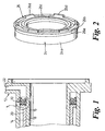
- the invention seal assembly 10 is seen in FIG. 1 in use in an angular hydraulic cylinder and piston assembly, such for example as a slave cylinder assembly for operating the throw-out bearing of a vehicular clutch wherein the cylinder and piston assembly is disposed concentrically around the drive shaft connecting the clutch to the gear box of the vehicle.
- an angular hydraulic cylinder and piston assembly such for example as a slave cylinder assembly for operating the throw-out bearing of a vehicular clutch wherein the cylinder and piston assembly is disposed concentrically around the drive shaft connecting the clutch to the gear box of the vehicle.
- the slave cylinder assembly includes a housing 12 provided with concentric tubular members 14 and 16 preferably cast integrally with housing 12. Members 14 and 16 coactively define an annular cylindrical chamber 18, and an annular piston 20 is slidably positioned in chamber 18.
- Seal assembly 10 is disposed in chamber 18 on one side of annular piston 20 so that hydraulic fluid introduced into the annular chamber 18 through a passageway 22 in housing 12 displaces the seal assembly 10 and piston 20 to the left as seen in FIG. 1, thereby displacing to the left a throw-out bearing engaged by the free end of the annular piston.
- the throw-out bearing in turn engages the release fingers of the clutch of the vehicle in known manner to disengage the clutch.
- Seal assembly 10 includes an annular insert member 24 and an annular elastomeric member 26.
- Annular insert member 24 (FIG. 5) is formed in a suitable injection molding process of a suitable plastic material such as a glass reinforced plastics or a mineral filled plastics.
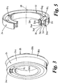
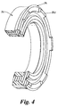
- Insert member 24 is in the form of a ring member and has an I-beam cross-sectional configuration including an outer annular flange structure 24a centered on an axis 28, an inner annular flange structure 24b centered on the axis concentrically within the outer annular flange structure, and an annular web structure 24c extending radially between the inner and outer annular flange structures.
- Web structure 24c has a left annular radial face 24d coacting with left portions 24e, 24f of the inner and outer annular flange structures to define a left continuous annular groove 30 and has a right annular radial face 24g coacting with right portions 24h and 24i of the inner and outer flange structures to define a right continuous annular groove 32.
- Web structure 24c further defines a plurality of circumferentially spaced circular holes 24j extending axially through the web structure between the left and right grooves. Holes 24j may have any desired diameter but preferably, and as shown, extend the full height of the web structure.
- ring member 24 is coated with a suitable adhesive or bonding agent and placed in a suitable mold where, in a known flashless molding process, elastomeric material is molded around the insert member. More specifically, and as seen in FIG. 6, ring member 24 is positioned in an annular mold cavity 34a defined by a mold part 34; a further mold part 36 is affixed to mold part 34 and defines a mold cavity 36a coacting with mold cavity 34a to define the complete mold cavity; and elastomeric material in molten form is injected into the mold cavity through a sprue 38 defined by a sprue bushing 40 positioned in mold part 34.
- the molten elastomeric material flows through sprue 38 and into mold cavity 34a, 36a and specifically fills groove 30, fills holes 24j, fills groove 32, and fills mold cavity 36a to define a seal structure 26a.
- mold parts 36 and 34 are separated and the seal assembly comprising ring member 24 and elastomeric member 26 molded thereto is removed from the mold.
- seal structure 26a In the final configuration of the seal assembly, elastomeric material fills the left groove 30; fills the circumferentially spaced holes 24j; fills the right groove 32; and extends to the right of the ring member 24 (as viewed in the drawings) to define the seal structure 26a.
- Seal structure 26a (FIGS. 2, 3 and 4) defines an outer annular lip sealing surface 26b having a relaxed configuration positioned radially outwardly and to the right of the annular outer insert structure 24a and an inner annular lip sealing surface 26b having a relaxed configuration radially inwardly and to the right of the annular inner insert structure 24b.
- Seal structure 26 further defines an annular groove 26c between the inner and outer lip sealing surfaces to facilitate flexing movement of the inner and outer sealing surfaces between their relaxed and their working positions. Seal structure 26 further desirably includes a plurality of circumferentially spaced spacer portions 26d.
- seal assembly 10 In use in a concentric slave cylinder assembly, and as best seen in FIGS. 1 and 7, seal assembly 10 is received in annular bore 18 with insert member 24 maintaining a running clearance with the concentric walls defining the annular bore and with lip sealing surfaces 26a and 26b sealingly engaging the inner and outer annular surfaces of the bore to define a fluid pressure chamber in the right side of the bore acting to urge the seal assembly and the piston to the left to actuate the clutch in known manner.
- Spacers 26d operate to prevent movement of the seal structure to a position at the extreme right end of bore 18 where pressurized fluid entering passage 22 would have no access to the right face of the seal.
- the seal structure is shown in it relaxed configuration by the dash lines in FIG. 7 and is shown by the solid lines in FIG. 7 in its working position in sealing engagement with the inner and outer annular surfaces defining the annular bore.
- the seal assembly of the invention will be seen to minimize the disadvantages of the prior art seal assemblies.
- the invention seal assembly is simple and inexpensive in construction; the invention seal assembly is durable and provides a long product life; the invention seal assembly, by virtue of the close running clearance between the rigid insert member and the walls of the bore, is precluded from cocking in the bore; the strength and rigidity provided by the insert member precludes excessive squirming of the elastomeric material as the seal assembly moves in the bore whereby to minimize friction in the seal assembly; and the invention seal assembly, by virtue of its smooth, low friction non-squirming movement in the cylinder bore, minimizes the system hysteresis effect.
Landscapes
- Engineering & Computer Science (AREA)
- General Engineering & Computer Science (AREA)
- Mechanical Engineering (AREA)
- Manufacturing & Machinery (AREA)
- Hydraulic Clutches, Magnetic Clutches, Fluid Clutches, And Fluid Joints (AREA)
- Sealing Devices (AREA)
- Gasket Seals (AREA)
- Sealing With Elastic Sealing Lips (AREA)
- Pistons, Piston Rings, And Cylinders (AREA)
Claims (6)
- Dispositif d'étanchéité (10) comprenant une structure d'insert annulaire (24) composée d'une matière rigide centrée sur un axe et présentant une structure extérieure annulaire (24a), une structure intérieure annulaire (24b), des faces radiales annulaires gauche et droite (24d, 24g) et une rainure annulaire continue (32) dans ladite face radiale droite; et un élément d'étanchéité annulaire (26) composé d'une matière élastomère collé sur la structure d'insert, remplissant ladite rainure (32) et s'étendant vers la droite de la structure d'insert pour former une structure d'étanchéité définissant une surface d'étanchéité extérieure (26b) présentant une configuration relâchée positionnée radialement vers l'extérieur et vers la droite de la structure d'insert extérieure annulaire (24a), et une surface d'étanchéité annulaire intérieure (26b) présentant une configuration relâchée radialement vers l'intérieur et vers la droite de la structure d'insert intérieure annulaire (24b), l'ensemble étant caractérisé en ce que la structure d'insert (24) présente une configuration de section transversale en double T comprenant une structure d'aile annulaire extérieure (24a) formant la structure extérieure annulaire, et une structure d'aile annulaire intérieure (24b) formant la structure intérieure annulaire, et une structure d'âme annulaire (24c) s'étendant radialement entre les structures d'aile intérieure et extérieure et présentant une face gauche (24d) agissant conjointement avec les parties gauches (24e, 24f) des structures d'aile annulaires intérieure et extérieure (24b, 24a) pour former une rainure gauche (30) et agissant conjointement avec les parties droites des structures d'aile annulaires intérieure et extérieure (24b, 24a) pour former la rainure droite (32); et une pluralité de trous circonférentiellement espacés (24j) s'étend à travers la structure d'âme et relie les rainures gauche et droite, la matière élastomère remplissant également la rainure gauche (30) et les trous (24j).
- Dispositif d'étanchéité selon la revendication 1, caractérisé en ce que la structure d'étanchéité (26) est libre de se plier lorsqu'on l'utilise, afin de permettre à la surface d'étanchéité annulaire intérieure (26b) d'adopter une position de travail en alignement approximatif avec la surface annulaire radialement intérieure de la structure d'aile intérieure (24b), et de permettre à la surface d'étanchéité annulaire extérieure (26b) d'adopter une position de travail en alignement approximatif avec la surface annulaire radialement extérieure de la structure d'aile extérieure (24a).
- Dispositif d'étanchéité selon la revendication 1 ou 2, caractérisé en ce que l'élément d'étanchéité (26) définit une rainure annulaire (26c) entre les surfaces d'étanchéité intérieure et extérieure en vue de faciliter le mouvement de pliage des surfaces d'étanchéité intérieure et extérieure vers leur position de travail.
- Dispositif d'étanchéité selon l'une quelconque des revendications 1 à 3, caractérisé en ce que l'élément d'étanchéité comprend des parties d'écartement axialement saillantes (26d) destinées à empêcher tout contact direct total du joint avec une extrémité d'un alésage associé.
- Ensemble de cylindre concentrique comprenant un dispositif d'étanchéité selon l'une quelconque des revendications 1 à 4 pour sceller un piston annulaire à l'intérieur d'un alésage annulaire.
- Procédé pour fabriquer un dispositif d'étanchéité selon la revendication 1, comprenant les étapes consistant à:mouler un insert annulaire présentant une configuration de section transversale en double T comprenant une structure d'aile annulaire extérieure (24a) formant la structure extérieure annulaire, et une structure d'aile annulaire intérieure (24b) formant la structure intérieure annulaire, et une structure d'âme annulaire (24c) s'étendant radialement entre les structures d'aile intérieure et extérieure et présentant une face gauche (24d) agissant conjointement avec les parties gauches (24e, 24f) des structures d'aile annulaires intérieure et extérieure (24b, 24a) pour former la rainure gauche (30), et agissant conjointement avec les parties droites des structures d'aile annulaires intérieure et extérieure (24b, 24a) pour former la rainure droite (32); et une pluralité de trous circonférentiellement espacés (24j) s'étendant à travers la structure d'âme et reliant les rainures gauche et droite, la matière élastomère remplissant également la rainure gauche (30) et les trous (24j).revêtir l'insert d'un adhésif ou d'un agent de liaison;placer l'insert revêtu dans un moule définissant une ou plusieurs cavité(s) autour de l'insert;injecter une matière élastomère dans ladite ou lesdites cavité(s) afin de former un joint annulaire collé sur l'insert et remplissant lesdites rainures gauche et droite (30, 32) et lesdits trous (24j), et s'étendant vers la droite de la structure d'insert pour former une structure d'étanchéité définissant une surface d'étanchéité annulaire extérieure (26b) présentant une configuration relâchée positionnée radialement vers l'extérieur et vers la droite de la structure d'insert extérieure annulaire (24a), et une surface d'étanchéité annulaire intérieure (26b) présentant une configuration relâchée positionnée radialement vers l'intérieur et vers la droite de la structure d'insert intérieure annulaire (24b); etretirer le dispositif d'étanchéité terminé hors du moule.
Applications Claiming Priority (2)
| Application Number | Priority Date | Filing Date | Title |
|---|---|---|---|
| US09/092,743 US6196552B1 (en) | 1998-06-08 | 1998-06-08 | Seal assembly for annular hydraulic cylinder |
| US92743 | 1998-06-08 |
Publications (3)
| Publication Number | Publication Date |
|---|---|
| EP0964191A2 EP0964191A2 (fr) | 1999-12-15 |
| EP0964191A3 EP0964191A3 (fr) | 2000-09-06 |
| EP0964191B1 true EP0964191B1 (fr) | 2005-03-30 |
Family
ID=22234899
Family Applications (1)
| Application Number | Title | Priority Date | Filing Date |
|---|---|---|---|
| EP99304170A Expired - Lifetime EP0964191B1 (fr) | 1998-06-08 | 1999-05-28 | Dispositif d'étanchéité pour cylindre hydraulique annulaire et son procédé de fabrication |
Country Status (5)
| Country | Link |
|---|---|
| US (1) | US6196552B1 (fr) |
| EP (1) | EP0964191B1 (fr) |
| JP (1) | JP2000009231A (fr) |
| DE (1) | DE69924426T2 (fr) |
| GB (1) | GB2340897B (fr) |
Families Citing this family (45)
| Publication number | Priority date | Publication date | Assignee | Title |
|---|---|---|---|---|
| DE19839597A1 (de) * | 1998-08-31 | 2000-03-02 | Continental Teves Ag & Co Ohg | Dichtungseinsatz, insbesondere für einen Kolben einer hydraulischen Fahrzeugbremsanlage |
| US20040239047A1 (en) * | 2001-08-16 | 2004-12-02 | Kent Edwin J. | Composite fuel permeation barrier seal |
| FR2829429B1 (fr) | 2001-09-12 | 2003-12-12 | Skf Ab | Dispositif de butee de suspension |
| FR2832201B1 (fr) | 2001-11-13 | 2004-03-19 | Skf Ab | Dispositif tendeur instrumente et procede de controle associe |
| FR2835297B1 (fr) | 2002-01-29 | 2004-04-16 | Skf Ab | Support de fixation, palier a roulement et procede de montage associes |
| FR2841304B1 (fr) * | 2002-06-20 | 2007-01-05 | Skf Ab | Dispositif de tension pour mise en precontrainte d'une tige et procede de tension associe |
| FR2841990B1 (fr) * | 2002-07-02 | 2005-07-29 | Skf Ab | Dispositif de palier a roulement instrumente et moteur electrique ainsi equipe |
| US6843480B2 (en) * | 2002-08-07 | 2005-01-18 | Baker Hughes Incorporated | Seal ring for well completion tools |
| FR2851624B1 (fr) * | 2003-02-26 | 2006-03-31 | Skf Ab | Palier a roulement instrumente |
| FR2853165B1 (fr) * | 2003-03-27 | 2005-12-02 | Skf Ab | Ensemble capteur, et boitier pour la realisation d'un tel ensemble. |
| FR2853065B1 (fr) * | 2003-03-27 | 2006-01-06 | Skf Ab | Instrument de mesure portatif, notamment pur la pratique sportive. |
| US20040222623A1 (en) * | 2003-05-05 | 2004-11-11 | Walters Paul A. | Sealing assembly for a steering column assembly |
| FR2856447B1 (fr) * | 2003-06-18 | 2005-09-09 | Skf Ab | Butee de debrayage et procede de montage |
| FR2856757B1 (fr) * | 2003-06-27 | 2006-10-20 | Skf Ab | Palier a roulement instrumente et codeur pour ensemble capteur d'informations |
| FR2858376B1 (fr) * | 2003-07-28 | 2006-03-03 | Skf France | Dispositif de palier a roue libre avec limitateur de couple. |
| FR2860847B1 (fr) | 2003-10-14 | 2006-03-31 | Skf Ab | Dispositif de butee de debrayage |
| WO2005054725A1 (fr) * | 2003-12-05 | 2005-06-16 | Siemens Aktiengesellschaft | Dispositif, procede pour produire ledit dispositif ; dispositif de chambre et dispositif de transfert |
| FR2872558B1 (fr) * | 2004-07-02 | 2006-09-29 | Skf Ab | Butee de debrayage et procede de fabrication |
| JP4869575B2 (ja) * | 2004-09-28 | 2012-02-08 | 三菱電線工業株式会社 | シール |
| US7252293B2 (en) * | 2005-02-04 | 2007-08-07 | Press-Seal Gasket Corporation | Two-part gasket for pipe-to-pipe connections |
| US20090180721A1 (en) * | 2005-02-15 | 2009-07-16 | Stellario Barbera | Encoding Bearing Device and Rotating Machine |
| FR2882580B1 (fr) * | 2005-02-28 | 2007-05-25 | Skf Ab | Dispositif de galet tendeur de courroie instrumente et procede de controle associe |
| US7461907B2 (en) * | 2005-07-18 | 2008-12-09 | Bendix Spicer Foundation Brake Llc | Rod/seal bearing arrangement utilizing locking fingers |
| CA114459S (en) * | 2005-08-05 | 2008-03-11 | Faster Spa | Fluid seal |
| US8091864B2 (en) * | 2005-12-20 | 2012-01-10 | Ds Smith Plastics Limited | Valve for a fluid flow connector having an overmolded plunger |
| FR2902699B1 (fr) * | 2006-06-26 | 2010-10-22 | Skf Ab | Dispositif de butee de suspension et jambe de force. |
| JP4894397B2 (ja) * | 2006-07-28 | 2012-03-14 | アイシン精機株式会社 | 油圧式クラッチレリーズ装置用シール |
| FR2906587B1 (fr) * | 2006-10-03 | 2009-07-10 | Skf Ab | Dispositif de galet tendeur. |
| FR2906858B1 (fr) * | 2006-10-04 | 2008-12-05 | Skf Ab | Dispositif de poulie debrayable. |
| US7845535B2 (en) | 2006-10-06 | 2010-12-07 | Tyco Healthcare Group Lp | Surgical instrument having a plastic surface |
| US7866525B2 (en) | 2006-10-06 | 2011-01-11 | Tyco Healthcare Group Lp | Surgical instrument having a plastic surface |
| FR2910129B1 (fr) * | 2006-12-15 | 2009-07-10 | Skf Ab | Dispositif de palier a roulement instrumente |
| FR2913081B1 (fr) * | 2007-02-27 | 2009-05-15 | Skf Ab | Dispositif de poulie debrayable |
| DE102008027828A1 (de) * | 2007-06-20 | 2008-12-24 | Dichtungstechnik G. Bruss Gmbh & Co. Kg | Radialwellendichtring |
| DE102008016654B4 (de) * | 2008-04-01 | 2019-02-21 | Elringklinger Ag | Autark-Kettenspanner mit Doppeldichtring |
| US8419021B2 (en) * | 2008-10-31 | 2013-04-16 | Ti Group Automotive Systems, L.L.C. | Ring seal with insert |
| CN103827532B (zh) * | 2011-08-05 | 2016-06-22 | 舍弗勒技术股份两合公司 | 从动缸 |
| DE102012212292A1 (de) | 2011-08-05 | 2013-02-07 | Schaeffler Technologies AG & Co. KG | Ausrücksystem |
| EP2880329B1 (fr) * | 2012-08-02 | 2017-04-19 | Schaeffler Technologies AG & Co. KG | Cylindre récepteur pour un dispositif de débrayage hydraulique en vue d'actionner un embrayage |
| WO2014134600A1 (fr) * | 2013-03-01 | 2014-09-04 | Vita-Mix Corporation | Système de mélange |
| DE102019219431A1 (de) * | 2019-09-11 | 2021-03-11 | Continental Teves Ag & Co. Ohg | Kolbendichtung für eine Kolbeneinheit eines hydraulischen Bremssystems |
| KR102818879B1 (ko) * | 2020-03-26 | 2025-06-11 | 현대모비스 주식회사 | 차량용 패킹장치 |
| EP3896416B1 (fr) * | 2020-04-16 | 2025-08-13 | TE Connectivity Sensors France | Capteur de couple |
| US20220065348A1 (en) * | 2020-08-28 | 2022-03-03 | Trelleborg Sealing Solutions Germany Gmbh | Swivel seal assembly |
| KR102723367B1 (ko) * | 2024-04-30 | 2024-10-28 | 이현근 | 일체형 패킹 어셈블리 |
Citations (1)
| Publication number | Priority date | Publication date | Assignee | Title |
|---|---|---|---|---|
| US3848880A (en) * | 1972-06-09 | 1974-11-19 | Tanner Eng Co | Fluid seal |
Family Cites Families (23)
| Publication number | Priority date | Publication date | Assignee | Title |
|---|---|---|---|---|
| FR675545A (fr) | 1929-05-22 | 1930-02-11 | Dispositif d'épuration d'eau pour usages industriels divers | |
| GB561189A (en) | 1942-11-02 | 1944-05-09 | Hall & Hall Ltd | Improvements in or relating to packings for seals, stuffing boxes, pistons and the like |
| DE871236C (de) | 1943-07-11 | 1953-03-19 | Wetzell Gummiwerke Ag | Dichtungselement mit Stuetzkoerper und elastischen Dichtlippen |
| GB805253A (en) | 1955-11-25 | 1958-12-03 | Trist & Co Ltd Ronald | Improvements relating to packing rings |
| US2914369A (en) | 1958-03-18 | 1959-11-24 | Blackhawk Mfg Co | Fluid seal |
| GB1026354A (en) | 1962-03-16 | 1966-04-20 | Trist Mouldings & Seals Ltd | Improvements relating to packing rings |
| GB1075111A (en) | 1963-11-28 | 1967-07-12 | Hall & Hall Ltd | Improvements in or relating to sealing rings |
| FR1428571A (fr) | 1965-01-05 | 1966-02-18 | Joint d'étanchéité annulaire perfectionné | |
| FR1528824A (fr) | 1967-04-27 | 1968-06-14 | Commissariat Energie Atomique | Joint d'étanchéité annulaire |
| US4382972A (en) | 1975-08-04 | 1983-05-10 | Fritzsche Dodge & Olcott Inc. | Flavoring compositions and flavored comestibles containing alkyl 2,3-dihydro-3(1'-hydroxyalkylidene)-2-oxo-5-alkylfuran-4-carboxylates |
| DE2654452C2 (de) | 1976-12-01 | 1983-01-05 | Kaco Gmbh + Co, 7100 Heilbronn | Dichtung |
| US4281590A (en) * | 1979-01-02 | 1981-08-04 | Weaver Joe T | Piston construction for reciprocating pumps |
| US4428590A (en) | 1981-11-19 | 1984-01-31 | Utex Industries, Inc. | Anti-extrusion sealing device with hinge-like bridge section |
| US4601374A (en) | 1982-04-22 | 1986-07-22 | Federal-Mogul Corporation | Hydraulic clutch piston and seal |
| US4577549A (en) | 1984-03-28 | 1986-03-25 | Automotive Products Plc | Hydraulic cylinder provided with low friction plated internal surface |
| US4827834A (en) | 1987-06-05 | 1989-05-09 | Automotive Products, Plc | Four point seal |
| US4821627A (en) | 1987-06-05 | 1989-04-18 | Leigh Monstevens Keith V | Piston and cylinder assembly |
| US5092125A (en) | 1987-10-29 | 1992-03-03 | Automotive Products Plc | Seal |
| GB9112949D0 (en) * | 1991-06-15 | 1991-08-07 | Gen Motors France | Master cylinder and end fitting therefor |
| DE4129370C2 (de) * | 1991-09-04 | 2001-11-22 | Mannesmann Sachs Ag | Hydraulisch betätigbarer Ausrücker mit Stützring und Stützschulter |
| US5275387A (en) * | 1992-04-09 | 1994-01-04 | Power Components, Inc. | Gas spring |
| CA2083552C (fr) * | 1992-04-09 | 2003-02-11 | Jonathan P. Cotter | Soupape de securite |
| DE19615157A1 (de) * | 1996-04-17 | 1997-10-23 | Lucas Ind Plc | Ringförmiges Dichtelement |
-
1998
- 1998-06-08 US US09/092,743 patent/US6196552B1/en not_active Expired - Lifetime
-
1999
- 1999-05-28 DE DE69924426T patent/DE69924426T2/de not_active Expired - Lifetime
- 1999-05-28 GB GB9912389A patent/GB2340897B/en not_active Expired - Fee Related
- 1999-05-28 EP EP99304170A patent/EP0964191B1/fr not_active Expired - Lifetime
- 1999-05-31 JP JP11151504A patent/JP2000009231A/ja active Pending
Patent Citations (1)
| Publication number | Priority date | Publication date | Assignee | Title |
|---|---|---|---|---|
| US3848880A (en) * | 1972-06-09 | 1974-11-19 | Tanner Eng Co | Fluid seal |
Also Published As
| Publication number | Publication date |
|---|---|
| GB2340897A (en) | 2000-03-01 |
| JP2000009231A (ja) | 2000-01-11 |
| US6196552B1 (en) | 2001-03-06 |
| EP0964191A2 (fr) | 1999-12-15 |
| GB9912389D0 (en) | 1999-07-28 |
| DE69924426D1 (de) | 2005-05-04 |
| DE69924426T2 (de) | 2006-03-09 |
| GB2340897B (en) | 2002-02-20 |
| EP0964191A3 (fr) | 2000-09-06 |
Similar Documents
| Publication | Publication Date | Title |
|---|---|---|
| EP0964191B1 (fr) | Dispositif d'étanchéité pour cylindre hydraulique annulaire et son procédé de fabrication | |
| US5287951A (en) | Hydraulically actuable releaser for a motor vehicle friction clutch | |
| US4827834A (en) | Four point seal | |
| DE10205177B4 (de) | Hydraulisches System | |
| WO1988009889A1 (fr) | Joint d'etancheite pour piston | |
| CN104114891B (zh) | 用于液压离合器致动装置的同心从动缸 | |
| JPH0156939B2 (fr) | ||
| US7467702B2 (en) | Clutch release bearing and method of manufacture | |
| EP2916047B1 (fr) | Procédé de fabrication d'un dispositif d'étanchéité, et dispositif d'étanchéité | |
| JP2004060893A (ja) | 軸スリーブ | |
| KR20050013557A (ko) | 자동차용 유압 시스템 | |
| EP1104507B1 (fr) | Cylindres hydrauliques | |
| KR20060093338A (ko) | 축방향 및 방사상 방향으로 인접한 두 개의 클러치를포함하는 변속기의 클러치 어셈블리 | |
| KR100433840B1 (ko) | 환형 밀봉 요소 | |
| JPS586097B2 (ja) | 位置を非接触走査しうるピストン | |
| CN102345593B (zh) | 特别是用于车辆中流体组件的支撑环和车辆用的流体组件 | |
| KR20210058710A (ko) | 유체 펌프 | |
| US5377580A (en) | Piston with an encompassing seal | |
| US5607637A (en) | Method of manufacturing a transmission fluid filter | |
| KR20030077630A (ko) | 지지 커넥터 요소를 구비한 피스톤/실린더 장치용 피스톤,특히 완충기 피스톤 | |
| JP2008519945A (ja) | エラストマベアリングを製造するための方法ならびにこれにより製造されたスリーブベアリングならびに製造するための装置 | |
| CN101765725A (zh) | 压力介质操作的离合器执行机构 | |
| KR100919347B1 (ko) | 결합 장치 및 유압 클러치 실린더 | |
| CN102575770B (zh) | 密封装置 | |
| JP2001082602A (ja) | 密封リングを含む合成樹脂製ホルダ |
Legal Events
| Date | Code | Title | Description |
|---|---|---|---|
| PUAI | Public reference made under article 153(3) epc to a published international application that has entered the european phase |
Free format text: ORIGINAL CODE: 0009012 |
|
| AK | Designated contracting states |
Kind code of ref document: A2 Designated state(s): DE FR GB IT |
|
| AX | Request for extension of the european patent |
Free format text: AL;LT;LV;MK;RO;SI |
|
| PUAL | Search report despatched |
Free format text: ORIGINAL CODE: 0009013 |
|
| AK | Designated contracting states |
Kind code of ref document: A3 Designated state(s): AT BE CH CY DE DK ES FI FR GB GR IE IT LI LU MC NL PT SE |
|
| AX | Request for extension of the european patent |
Free format text: AL;LT;LV;MK;RO;SI |
|
| 17P | Request for examination filed |
Effective date: 20010226 |
|
| AKX | Designation fees paid |
Free format text: DE FR GB IT |
|
| 17Q | First examination report despatched |
Effective date: 20030929 |
|
| GRAP | Despatch of communication of intention to grant a patent |
Free format text: ORIGINAL CODE: EPIDOSNIGR1 |
|
| RTI1 | Title (correction) |
Free format text: SEAL ASSEMBLY FOR ANNULAR HYDRAULIC CYLINDER AND ITS METHOD OF MANUFACTURING |
|
| GRAS | Grant fee paid |
Free format text: ORIGINAL CODE: EPIDOSNIGR3 |
|
| GRAA | (expected) grant |
Free format text: ORIGINAL CODE: 0009210 |
|
| RAP1 | Party data changed (applicant data changed or rights of an application transferred) |
Owner name: FTEAUTOMOTIVE GMBH & CO. KG |
|
| AK | Designated contracting states |
Kind code of ref document: B1 Designated state(s): DE FR GB IT |
|
| REG | Reference to a national code |
Ref country code: GB Ref legal event code: FG4D |
|
| REF | Corresponds to: |
Ref document number: 69924426 Country of ref document: DE Date of ref document: 20050504 Kind code of ref document: P |
|
| RAP2 | Party data changed (patent owner data changed or rights of a patent transferred) |
Owner name: FTE AUTOMOTIVE GMBH |
|
| REG | Reference to a national code |
Ref country code: GB Ref legal event code: 732E |
|
| PLBE | No opposition filed within time limit |
Free format text: ORIGINAL CODE: 0009261 |
|
| STAA | Information on the status of an ep patent application or granted ep patent |
Free format text: STATUS: NO OPPOSITION FILED WITHIN TIME LIMIT |
|
| ET | Fr: translation filed | ||
| 26N | No opposition filed |
Effective date: 20060102 |
|
| REG | Reference to a national code |
Ref country code: FR Ref legal event code: TP Ref country code: FR Ref legal event code: CD |
|
| REG | Reference to a national code |
Ref country code: FR Ref legal event code: PLFP Year of fee payment: 18 |
|
| REG | Reference to a national code |
Ref country code: FR Ref legal event code: PLFP Year of fee payment: 19 |
|
| PGFP | Annual fee paid to national office [announced via postgrant information from national office to epo] |
Ref country code: GB Payment date: 20170630 Year of fee payment: 19 Ref country code: FR Payment date: 20170512 Year of fee payment: 19 |
|
| PGFP | Annual fee paid to national office [announced via postgrant information from national office to epo] |
Ref country code: IT Payment date: 20170428 Year of fee payment: 19 |
|
| PGFP | Annual fee paid to national office [announced via postgrant information from national office to epo] |
Ref country code: DE Payment date: 20180726 Year of fee payment: 20 |
|
| GBPC | Gb: european patent ceased through non-payment of renewal fee |
Effective date: 20180528 |
|
| PG25 | Lapsed in a contracting state [announced via postgrant information from national office to epo] |
Ref country code: GB Free format text: LAPSE BECAUSE OF NON-PAYMENT OF DUE FEES Effective date: 20180528 Ref country code: IT Free format text: LAPSE BECAUSE OF NON-PAYMENT OF DUE FEES Effective date: 20180528 Ref country code: FR Free format text: LAPSE BECAUSE OF NON-PAYMENT OF DUE FEES Effective date: 20180531 |
|
| REG | Reference to a national code |
Ref country code: DE Ref legal event code: R071 Ref document number: 69924426 Country of ref document: DE |