EP0964247A2 - Examination par ultrason de pieces revêtues - Google Patents
Examination par ultrason de pieces revêtues Download PDFInfo
- Publication number
- EP0964247A2 EP0964247A2 EP99630050A EP99630050A EP0964247A2 EP 0964247 A2 EP0964247 A2 EP 0964247A2 EP 99630050 A EP99630050 A EP 99630050A EP 99630050 A EP99630050 A EP 99630050A EP 0964247 A2 EP0964247 A2 EP 0964247A2
- Authority
- EP
- European Patent Office
- Prior art keywords
- angle
- coated
- coating
- dryer
- transducer
- Prior art date
- Legal status (The legal status is an assumption and is not a legal conclusion. Google has not performed a legal analysis and makes no representation as to the accuracy of the status listed.)
- Withdrawn
Links
- 239000000463 material Substances 0.000 claims abstract description 24
- 230000032798 delamination Effects 0.000 claims abstract description 17
- 229920005479 Lucite® Polymers 0.000 claims abstract description 16
- 239000004926 polymethyl methacrylate Substances 0.000 claims abstract description 16
- 239000002184 metal Substances 0.000 claims abstract description 14
- 229910052751 metal Inorganic materials 0.000 claims abstract description 14
- 238000000034 method Methods 0.000 claims description 50
- 238000000576 coating method Methods 0.000 claims description 44
- 239000011248 coating agent Substances 0.000 claims description 42
- 230000008878 coupling Effects 0.000 claims description 10
- 238000010168 coupling process Methods 0.000 claims description 10
- 238000005859 coupling reaction Methods 0.000 claims description 10
- 230000003746 surface roughness Effects 0.000 claims description 3
- 230000000149 penetrating effect Effects 0.000 claims 4
- 239000011253 protective coating Substances 0.000 claims 2
- 230000001902 propagating effect Effects 0.000 claims 1
- 229910001018 Cast iron Inorganic materials 0.000 abstract description 35
- 230000007547 defect Effects 0.000 abstract description 13
- 238000012360 testing method Methods 0.000 abstract description 12
- 238000001514 detection method Methods 0.000 abstract description 5
- 239000000758 substrate Substances 0.000 description 11
- 238000007689 inspection Methods 0.000 description 10
- XLYOFNOQVPJJNP-UHFFFAOYSA-N water Substances O XLYOFNOQVPJJNP-UHFFFAOYSA-N 0.000 description 9
- 238000005266 casting Methods 0.000 description 6
- 230000007246 mechanism Effects 0.000 description 5
- 230000008569 process Effects 0.000 description 3
- 238000003908 quality control method Methods 0.000 description 3
- 239000007921 spray Substances 0.000 description 3
- 238000005299 abrasion Methods 0.000 description 2
- 230000002411 adverse Effects 0.000 description 2
- 238000010276 construction Methods 0.000 description 2
- 238000007796 conventional method Methods 0.000 description 2
- 238000005336 cracking Methods 0.000 description 2
- 238000001035 drying Methods 0.000 description 2
- 238000005259 measurement Methods 0.000 description 2
- 238000009659 non-destructive testing Methods 0.000 description 2
- 230000000737 periodic effect Effects 0.000 description 2
- 238000012546 transfer Methods 0.000 description 2
- 238000002604 ultrasonography Methods 0.000 description 2
- 229910001369 Brass Inorganic materials 0.000 description 1
- XEEYBQQBJWHFJM-UHFFFAOYSA-N Iron Chemical group [Fe] XEEYBQQBJWHFJM-UHFFFAOYSA-N 0.000 description 1
- 229910000831 Steel Inorganic materials 0.000 description 1
- 239000010951 brass Substances 0.000 description 1
- 230000008859 change Effects 0.000 description 1
- 230000001010 compromised effect Effects 0.000 description 1
- 238000001816 cooling Methods 0.000 description 1
- 230000006378 damage Effects 0.000 description 1
- 238000013500 data storage Methods 0.000 description 1
- 230000001627 detrimental effect Effects 0.000 description 1
- 230000000694 effects Effects 0.000 description 1
- 239000000835 fiber Substances 0.000 description 1
- 239000012530 fluid Substances 0.000 description 1
- 238000003384 imaging method Methods 0.000 description 1
- 238000004519 manufacturing process Methods 0.000 description 1
- 150000002739 metals Chemical class 0.000 description 1
- 239000000203 mixture Substances 0.000 description 1
- 238000000275 quality assurance Methods 0.000 description 1
- 230000002285 radioactive effect Effects 0.000 description 1
- 230000008439 repair process Effects 0.000 description 1
- 239000007787 solid Substances 0.000 description 1
- 238000005507 spraying Methods 0.000 description 1
- 239000010959 steel Substances 0.000 description 1
- 238000003860 storage Methods 0.000 description 1
- 230000002889 sympathetic effect Effects 0.000 description 1
- 239000011800 void material Substances 0.000 description 1
Images



Classifications
-
- G—PHYSICS
- G01—MEASURING; TESTING
- G01N—INVESTIGATING OR ANALYSING MATERIALS BY DETERMINING THEIR CHEMICAL OR PHYSICAL PROPERTIES
- G01N29/00—Investigating or analysing materials by the use of ultrasonic, sonic or infrasonic waves; Visualisation of the interior of objects by transmitting ultrasonic or sonic waves through the object
- G01N29/04—Analysing solids
- G01N29/043—Analysing solids in the interior, e.g. by shear waves
-
- G—PHYSICS
- G01—MEASURING; TESTING
- G01N—INVESTIGATING OR ANALYSING MATERIALS BY DETERMINING THEIR CHEMICAL OR PHYSICAL PROPERTIES
- G01N29/00—Investigating or analysing materials by the use of ultrasonic, sonic or infrasonic waves; Visualisation of the interior of objects by transmitting ultrasonic or sonic waves through the object
- G01N29/04—Analysing solids
-
- G—PHYSICS
- G01—MEASURING; TESTING
- G01N—INVESTIGATING OR ANALYSING MATERIALS BY DETERMINING THEIR CHEMICAL OR PHYSICAL PROPERTIES
- G01N29/00—Investigating or analysing materials by the use of ultrasonic, sonic or infrasonic waves; Visualisation of the interior of objects by transmitting ultrasonic or sonic waves through the object
- G01N29/22—Details, e.g. general constructional or apparatus details
- G01N29/221—Arrangements for directing or focusing the acoustical waves
-
- G—PHYSICS
- G01—MEASURING; TESTING
- G01N—INVESTIGATING OR ANALYSING MATERIALS BY DETERMINING THEIR CHEMICAL OR PHYSICAL PROPERTIES
- G01N29/00—Investigating or analysing materials by the use of ultrasonic, sonic or infrasonic waves; Visualisation of the interior of objects by transmitting ultrasonic or sonic waves through the object
- G01N29/22—Details, e.g. general constructional or apparatus details
- G01N29/24—Probes
- G01N29/2487—Directing probes, e.g. angle probes
-
- G—PHYSICS
- G10—MUSICAL INSTRUMENTS; ACOUSTICS
- G10K—SOUND-PRODUCING DEVICES; METHODS OR DEVICES FOR PROTECTING AGAINST, OR FOR DAMPING, NOISE OR OTHER ACOUSTIC WAVES IN GENERAL; ACOUSTICS NOT OTHERWISE PROVIDED FOR
- G10K11/00—Methods or devices for transmitting, conducting or directing sound in general; Methods or devices for protecting against, or for damping, noise or other acoustic waves in general
- G10K11/18—Methods or devices for transmitting, conducting or directing sound
- G10K11/26—Sound-focusing or directing, e.g. scanning
-
- G—PHYSICS
- G01—MEASURING; TESTING
- G01N—INVESTIGATING OR ANALYSING MATERIALS BY DETERMINING THEIR CHEMICAL OR PHYSICAL PROPERTIES
- G01N2291/00—Indexing codes associated with group G01N29/00
- G01N2291/02—Indexing codes associated with the analysed material
- G01N2291/023—Solids
- G01N2291/0231—Composite or layered materials
-
- G—PHYSICS
- G01—MEASURING; TESTING
- G01N—INVESTIGATING OR ANALYSING MATERIALS BY DETERMINING THEIR CHEMICAL OR PHYSICAL PROPERTIES
- G01N2291/00—Indexing codes associated with group G01N29/00
- G01N2291/02—Indexing codes associated with the analysed material
- G01N2291/023—Solids
- G01N2291/0234—Metals, e.g. steel
-
- G—PHYSICS
- G01—MEASURING; TESTING
- G01N—INVESTIGATING OR ANALYSING MATERIALS BY DETERMINING THEIR CHEMICAL OR PHYSICAL PROPERTIES
- G01N2291/00—Indexing codes associated with group G01N29/00
- G01N2291/04—Wave modes and trajectories
- G01N2291/042—Wave modes
- G01N2291/0421—Longitudinal waves
-
- G—PHYSICS
- G01—MEASURING; TESTING
- G01N—INVESTIGATING OR ANALYSING MATERIALS BY DETERMINING THEIR CHEMICAL OR PHYSICAL PROPERTIES
- G01N2291/00—Indexing codes associated with group G01N29/00
- G01N2291/04—Wave modes and trajectories
- G01N2291/042—Wave modes
- G01N2291/0422—Shear waves, transverse waves, horizontally polarised waves
-
- G—PHYSICS
- G01—MEASURING; TESTING
- G01N—INVESTIGATING OR ANALYSING MATERIALS BY DETERMINING THEIR CHEMICAL OR PHYSICAL PROPERTIES
- G01N2291/00—Indexing codes associated with group G01N29/00
- G01N2291/04—Wave modes and trajectories
- G01N2291/044—Internal reflections (echoes), e.g. on walls or defects
-
- G—PHYSICS
- G01—MEASURING; TESTING
- G01N—INVESTIGATING OR ANALYSING MATERIALS BY DETERMINING THEIR CHEMICAL OR PHYSICAL PROPERTIES
- G01N2291/00—Indexing codes associated with group G01N29/00
- G01N2291/04—Wave modes and trajectories
- G01N2291/048—Transmission, i.e. analysed material between transmitter and receiver
-
- G—PHYSICS
- G01—MEASURING; TESTING
- G01N—INVESTIGATING OR ANALYSING MATERIALS BY DETERMINING THEIR CHEMICAL OR PHYSICAL PROPERTIES
- G01N2291/00—Indexing codes associated with group G01N29/00
- G01N2291/04—Wave modes and trajectories
- G01N2291/055—Angular incidence, perpendicular propagation
-
- G—PHYSICS
- G01—MEASURING; TESTING
- G01N—INVESTIGATING OR ANALYSING MATERIALS BY DETERMINING THEIR CHEMICAL OR PHYSICAL PROPERTIES
- G01N2291/00—Indexing codes associated with group G01N29/00
- G01N2291/10—Number of transducers
- G01N2291/101—Number of transducers one transducer
-
- G—PHYSICS
- G01—MEASURING; TESTING
- G01N—INVESTIGATING OR ANALYSING MATERIALS BY DETERMINING THEIR CHEMICAL OR PHYSICAL PROPERTIES
- G01N2291/00—Indexing codes associated with group G01N29/00
- G01N2291/26—Scanned objects
- G01N2291/263—Surfaces
- G01N2291/2632—Surfaces flat
-
- G—PHYSICS
- G01—MEASURING; TESTING
- G01N—INVESTIGATING OR ANALYSING MATERIALS BY DETERMINING THEIR CHEMICAL OR PHYSICAL PROPERTIES
- G01N2291/00—Indexing codes associated with group G01N29/00
- G01N2291/26—Scanned objects
- G01N2291/263—Surfaces
- G01N2291/2634—Surfaces cylindrical from outside
Definitions
- tissue paper and paper towel a web of paper fibers is formed and pressed against a Yankee dryer. After drying, the web is scraped from the surface of the Yankee dryer, giving the web a creped texture which gives the paper it's soft absorptive characteristics. Because only a single dryer is used the Yankee dryer is normally large, typically from twelve to twenty-five feet in diameter. Moreover, the Yankee dryer is heated by steam at pressures of up to 160 psig. A Yankee dryer may be 400 inches long and may have a total weight of over 100 tons. Because of its large size and high operating pressure, a Yankee dryer typically has a cylinder wall thickness of over two inches. Yankee dryers are generally formed from cast iron; a material which has good release characteristics if the surface is properly ground. Thus, the surface of a Yankee dryer requires periodic regrinding to maintain the proper surface finish.
- a Yankee dryer is a pressure vessel and the safety precautions typically employed with any pressure vessel or boiler must be observed.
- U.S. Patent No. 4,398,421 an apparatus for measuring the thickness of a work piece which is useful for measuring the thickness of steam boiler walls is disclosed. Determining the wall thickness of a Yankee dryer is useful but it is also desirable to detect small voids within the thickness of the dryer wall.
- Ultrasonic inspection systems have a limited capability for detecting small voids or finding voids near the surface of cast iron parts.
- Ultrasonic signals in cast iron are scattered and reflected from grain boundaries present in the cast iron. This characteristic of cast iron makes detecting small discontinuities very difficult. Even measurement of thickness in cast iron can be difficult to perform.
- Ultrasonic transducers typically have an interface zone of up to one-half inch where subsurface discontinuities can not be detected.
- X-ray methods are used for the inspection of Yankee dryer rolls. X-ray methods, however, require the use of radioactive sources which are cumbersome and dangerous. In practice, x-ray images are only made of limited portions of the Yankee dryer. Furthermore, x-ray imaging is not effective at detecting hair-line cracks because such cracks do not significantly reduce the density of the material. Hair-line cracks are, however, typically detectable by ultrasonics.
- the 5,681,996 patent and the 08/948,959 application relate to ultrasonic instruments for nondestructive testing of materials in general and for nondestructuring testing of large cast cylinders in particular.
- the invention of the subject application is related to the ultrasonic interrogation of coated materials in general and for nondestructive testing of coated, large cast cylinders in particular.
- the outside shell or surface of paper and tissue machine cast iron dryer cylinders becomes worn in service due to abrasion during operation.
- the primary cause of wear to the outside shell of a paper machine dryer cylinder is attributable to a doctor blade.
- a doctor blade is generally brought into intimate contact with the outside shell or surface of a dryer cylinder in order to scrape or crepe off the web of paper or tissue traveling over the dryer cylinder.
- metalspray compositions capable of being used for large cast iron dryer shells generally known to those skilled in the art.
- Metalspray application is also generally known to those skilled in the art. Essentially, molten metal is sprayed onto the surface or outer shell of a large cast iron dryer. Typically, at the outer edges of the metalspray flame, cold splatter, known to those skilled in the art, may be deposited onto the surface of the drying cylinder. The larger the arc of the metalspray, the more cold splatter that is deposited. Cold splatter is a miniature disbond of metalspray material between the metalspray coating and the substrate upon which the coating is applied. Detectable quantities of cold splatter cause problems related to heat transfer, surface quality, and other problems as can be appreciated by those skilled in the art. Such problems compromise the quality of the tissue or paper product being formed.
- dryer cylinders are often exposed to water streams. Although dryer cylinders are not usually purposefully exposed to water streams, such exposure does occur. If the outside shell or surface of a dryer cylinder has been metalsprayed, there will be a difference in the coefficient of thermal expansion between the metalspray coating and the cast iron substrate. When water contacts the metalsprayed shell, the shell and metalspray begin to cool. The metalspray will cool at one rate and the cast iron dryer cylinder will cool at another rate. The difference in the thermal coefficient between the two materials can cause cracking or disbonding of the metalspray.
- the metalspray If the metalspray is not properly adhered to the surface of the cast iron cylinder, the metalspray will likely fall or wear off at the location of the poor adherence during a paper or tissue making operation. If the metalspray wears or falls off, problems associated with poor heat transfer and surface quality will occur and a poor tissue or paper product will result.
- What is needed is a method for performing complete inspection of a coated cast iron dryer cylinder for quality control and assurance of thin metalspray adhesion to cast iron dryer shells.
- An ultrasonic transducer for detecting delamination and/or discontinuities in a thin layer of metalspray applied to a metal plate or the outside wall or surface of a cast iron dryer cylinder of this invention begins with the discovery that a high amplitude ultrasonic signal is generated when delaminations and/or discontinuities are detected. If no delaminations and/or discontinuities are present, no high amplitude ultrasonic signal of the metalspray is present.
- An ultrasonic signal is directed at a surface to be inspected at a particular angle, about ten percent of the signal will appear as Harris waves which propagate into the coated material at 90 degrees to the coated surface.
- the signal which propagates vertically is polarized, with the result that the signal detects delaminations and/or discontinuities with greatly improved signal to noise ratio.
- the particular angle is between that angle where the ultrasonic signal is refracted so as to propagate parallel to the coated surface of the metal plate or cylinder and that angle where the ultrasonic signal is reflected by the test plate.
- This polarized or birefingent signal/beam is called a Harris wave.
- the refracting signal continues to propagate along the surface of the solid until the angle of incidence is sufficiently great that the signal is totally reflected.
- an angle exists which produces a Harris wave which is particularly effective at detecting flaws within the surface of the coated material being tested because of a high signal-to-noise ratio that is five to twenty times larger than at normal inspection angles.
- the specific incident beam angle is approximately 66 degrees from the vertical.
- Lucite is believed to be a registered trademark of E. I. Du Pont De Nemours and Company.
- the invention can employ shear surface waves to affect the detection of subsurface defects with the critical angle changing depending on the ratio of the velocity of the selected wave in the refracting medium to the velocity of the selected wave in the incident medium.
- Figure 1 is an elevational isometric view of a dryer roll casting being inspected with ultrasonic energy and the results being recorded.
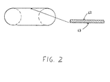
- Figure 2 is a perspective view of a dryer roll casting showing metalspray coating as applied to the cast iron outside diameter surface.
- Figure 3 is a schematic elevational view of an ultrasonic transducer projecting an ultrasonic signal through a Lucite medium into a coated material of a coated part or coated dryer cylinder.
- Figure 4 is a schematic elevational view of an ultrasonic transducer projecting an ultrasonic signal at an incidence angle which causes a refracting beam to travel along the surface of a coated part or coated dryer cylinder.
- Figure 5 is a schematic elevational view of an ultrasonic transducer projecting an ultrasonic signal at an incidence angle which causes the signal to reflect from the surface of a coated part or coated dryer cylinder.
- Figure 6 is a schematic elevational front view of an ultrasonic transducer projecting an ultrasonic signal of an incidence angle of this invention which produces an ultrasonic beam which has a high signal-to-noise ratio and which penetrates normal to the surface of a coated part or coated dryer.
- Figure 7 is a front elevational axonometric view of an apparatus for detecting delaminations and/or discontinuities in the metalspray coating applied to a dryer cylinder or more particularly, a Yankee dryer cylinder.
- FIG. 1 An ultrasonic Yankee dryer inspection apparatus 20 is shown in Figure 1.
- a Yankee dryer 22 is mounted on an inspection frame 24.
- the dryer 22 has a cylindrical coated surface 26 on which a tissue web is dried.
- the Yankee dryer 22 is mounted to a bearing 28 on the frame 24 and is caused to rotate by a drive mechanism (not shown).
- An ultrasonic transducer 30 is mounted to a crossfeed 32 which rides on a machine screw 34.
- the machine screw 34 is caused to rotate by a drive mechanism (not shown).
- the rotation of the machine screw 34 causes the crossfeed 32 with the ultrasonic transducer 30 mounted thereon to scan the surface 26 of the dryer 22 along a line parallel to the dryer axis 36.
- the spiral pattern 38 as shown in Figure 1, is shown widely spaced for illustrative purposes but is actually a tight spiral wherein the transducer advances along the surface 26 of the dryer 22 about 1/8 inches per revolution.
- An incident medium 40 couples the ultrasonic energy from the transducer to the coated surface of the Yankee dryer 22.
- a coupling fluid typically water
- Lucite 40 such as described in U.S. Patent No. 5,681,996, which could couple the ultrasonic energy from the transducer to the coated surface of the Yankee dryer 22.
- the output of the transducer is stored in digital format on a mass data storage device 42 such as a hard-disk or a DAT (Digital Audio Tape), etc. From the mass storage device 42 a computer 44 or oscilloscope (not shown) can process the data for display.
- a computer display 46 shows a plan view of the dryer 22 cylindrical coated surface 26 where discontinuities and/or delaminations 48 are displayed for a selected portion of the dryer coated surface 26.
- the computer can also be used to display the amplitude of the reflected signal for a particular location.
- a separate scan using conventional techniques may be required.
- the metalspray thickness of the dryer coated surface 26 is generally only about .020 inches, but may range from .1-.025 inches, if a discontinuity and/or delamination is found, a profile grind of the metalsprayed surface is warranted in order to repair the affected areas. Thus, the depth or length of any discontinuity is generally not needed for this application.
- Figure 2 shows a perspective view of a dryer roll casting.
- a metalspray coating surface 62 is applied to the dryer roll casting outside diameter top surface 63.
- the application process for metalspray and the reasons for applying a metalspray coating to a dryer roll casting are generally known to those skilled in the art as set forth in the Background section herein.
- the subject invention pertains to analyzing the metalspray coating once it has been applied to the dryer roll surface, to make sure the metalspray coating does not contain any deformities.
- a poor quality metalspray coating has significant adverse effects on the quality of paper or tissue produced on such a machine, as more fully explained hereinabove.
- FIG 3 illustrates an ultrasonic transducer 52 projecting a beam 54 of ultrasonic energy.
- the ultrasonic transducer 52 intimately cooperates with a Lucite medium 56.
- transducer 52 is shown as embedded in the Lucite medium in Figures 3-6, it should be understood that the transducer 52 may be positioned over the top surface of the Lucite medium in an appropriate manner such as by using a transducer wedge generally known to those skilled in the art.
- the ultrasonic beam 54 is positioned at an angle 57 with respect to a reference line 58 normal to the surface 60 of a coated surface 62.
- Harris waves 76 are produced which originate from the point 78 where the beam 66 impinges on the coated top surface 60.
- the Harris waves 76 propagate vertically down into the coated surface 62 opposite the normal line 58.
- Harris waves 76 are produced as the angle of incidence is increased from the angle 64 governed by the above equation, until as shown in Figure 5 the ultrasonic beam 80 is totally reflected from the coated top surface 60 at angle of reflection 83.
- the location or measure of the total reflected angle 83 can be determined empirically by measuring when Harris waves are no longer produced as the angle between the transducer 52 and the normal line increases. Empirically the total reflection angle is about 120 percent of the selected angle 64 where Harris waves are first produced.
- the arc 84 shown in Figure 5 is between the selected angle 64 governed by Snell's law and the angle 82 where total reflection occurs. Harris waves 76 are produced within this arc 84.
- an angle 86 illustrated in Figure 6 which has been found to have a very high signal-to-noise ratio, five to twenty times that of a typical ultrasonic interrogation beam. The signal-to-noise ratio may be at least 5, and can be 10 or higher.
- This angle 86, as shown in Figure 6, allows detection of voids as small as one millimeter in coated material such as a metalspray coating which typically are difficult to inspect with conventional ultrasound techniques.
- This high signal-to-noise-ratio angle 86 along which an ultrasonic beam 88 is directed, is approximately 66 degrees from the normal line 58 when the coupling medium 56 is Lucite and the coated surface 62 is a typical metalspray coating.
- the optimal angle depends on the velocity of sound in the coated material 62. Sound has three wave components in a coated metalsprayed surface: an S or shear wave, an L or longitudinal wave, and surface wave. The velocity of sound differs for each type of sound wave and therefore the optimal angle will depend on the type of wave being utilized. While shear waves may have practical advantages, longitudinal waves can be used. As dictated by the above equations the angle where a beam of longitudinal waves are refracted to the surface of V 2 and propagate along the surface of the coated plate and also generate Harris waves is about 66 degrees from the normal line 58.
- the ultrasonic transducer 30 used to inspect the coated surface 62 of a Yankee dryer 22 is shown in Figure 7.
- the transducer 30 employs an ultrasonic transducer 52 mounted on a carriage block 90.
- the carriage block 90 has ports 92 through which water or other coupling media can be supplied, if desired, as discussed in U.S. Patent No. 5,681,996, between the carriage block 90 and the coated surface 26 of a Yankee dryer 22.
- the carriage block cooperates with a Lucite medium 40.
- the ultrasonic transducer 52 is mounted in a cylinder 94 so that the angle between the transducer and the surface 26 may be adjusted.
- a threaded adjustment screw 96 is pivotally mounted by a universal joint which allows the screw 96 to rotate with respect to the cylinder 94. Rotation of the screw causes the angle between the transducer 52 and the surface 26 to change.
- the ultrasonic transducer of U.S. Application 08/948,959 could be used in place of the ultrasonic transducer 30.
- the ultrasonic transducer 52 can be fixedly attached to a simple transducer wedge, generally known to those skilled in the art, and manually maneuvered over the material being tested as further described herein.
- Figure 7 illustrates how small droplets 50 of molten metal band together as a metalspray coating is cured.
- voids 100 are formed.
- Figure 7 illustrates the way ultrasonic waves 98 penetrate into the coated surface 62 of a Yankee dryer 22 and are reflected 101 off small voids 100 in the depth of the coated material or at the connection point of the metalspray coating and cast iron substrate.
- the ultrasonic waves 102 refracted along the coated top surface 60. Returns from the surface waves 102 can be used to detect coated surface roughness which is also an important characteristic of the Yankee dryer coated surface 26.
- the ultrasonic beam or waves which penetrate 90 degrees to the surface of the Yankee dryer appear from tests conducted to be polarized, as it appears that the polarized Harris waves are effective at reducing detected scatter. Nevertheless, the exact reasons why the optimal angle has a uniquely high signal-to-noise ratio is empirically observed and is not limited to the suggested mechanism. Ultrasonic energy over a wide range has been used for ultrasonic testing upon other materials and ultrasonic frequencies of 1 to 10 MHz in particular have been found to be effective.
- the outside shell of paper and tissue machine cast iron dryers becomes worn in service due to abrasion during operation.
- the primary unit causing shell wear is a doctor blade.
- Those skilled in the art recognize that detrimental shell wear affects the quality of a paper/tissue product being produced.
- the cast iron surface of a used dryer cylinder is machined or ground smooth, and a metalspray is applied to the surface to rehabilitate the worn cast iron surface so that the dryer cylinder is capable of further use.
- Metalspray thickness of about .020 inches is deposited on the cast iron surfaces. A poor metalspray application will result in all the problems set forth previously hereinabove.
- the method according to the present invention can quickly demonstrate the quality of a metalspray adhesion.
- the metalspray may be evaluated for quality control purposes.
- the method according to the present invention will detect voids in the metalspray coatings and/or areas of cold splatter, or miniature disbonds of the metalspray material after the metalspray has been applied. Detectable quantities of cold splatter should be corrected in order to prevent the quality of the tissue or paper being formed from being compromised. Poor areas of metalspray application should be profiled down and the metalspray should be reapplied.
- the method according to the present invention can also demonstrate the quality of the metalspray after a dryer cylinder has been in use for some time.
- hot dryers are exposed to water streams when dryer sections are cleaned out and paper wads, known to those skilled in the art, are removed. Usually, these water sprays are not intended to contact dryer surfaces, but such occurrences do happen.
- the shell of the dryer cylinder is metalsprayed, there will be a difference in coefficient of thermal expansion between the metal sprayed surface and the cast iron substrate. When water contacts the dryer cylinder, the cylinder begins to cool, the metalsprayed coated surface at one rate and the cast iron substrate at another. This thermal difference can cause cracking or disbonding of the metalsprayed coated surface.
- the method of detection according to the present invention uses one transducer from one side of a cast iron metalsprayed dryer cylinder.
- a calibration reference standard to assist in determining depth of a flaw is not necessary, but may be used. Detection of delaminations/discontinuities in a thin layer of metalspray generates a high amplitude ultrasonic signal. If no delaminations/discontinuities are present, no high amplitude ultrasonic signals are present.
- Adhesion at the interface between the coated surface and the cast iron substrate will not transmit a large UT signal with the beam according to the present invention because there is good impedance between the two materials and no interfaces to reflect sound, as a void or delamination would. Lack of adhesion will cause a large noticeable signal.
- metalspray is typically applied to a roll surface in the following manner.
- the dryer cylinder to receive a coating is mounted to a bearing on a frame and is caused to rotate by a drive mechanism.
- a metal spray coating apparatus is typically mounted to a crossfeed mechanism along a line parallel to the dryer axis. As a dryer cylinder is rotated, the metals pray apparatus moves linearly from one end of the dryer cylinder to the other. The combination of the rotating motion of the dryer and linear motion of the metal spray apparatus causes the metalspray coating to be applied in a tight spiral pattern.
- a defect found closer to the outside surface of a piece being tested generates a higher amplitude ultrasonic signal than a defect detected further from the outside shell.
- signals observed .3 inches from the surface of the material being tested are much higher in amplitude than those signals observed from distances greater than .3 inches from the outside surface.
- the ultrasonic return signal When testing the coated metalspray, if a defect is found, the ultrasonic return signal will be extremely high because the thickness of a metalspray coating is generally only about .020 inches thick, much less than .3 inches as described above. If the return signal is not of a high amplitude, any defect found will not be within the metalspray coating.
- cold splatter should be observed in a spiral, circumferential pattern, as this is how metalspray is applied. Thus, if a high amplitude return signal is detected and a spiral, circumferential pattern of defects is detected, cold splatter in the metalspray has been found.
- velocity of sound as used in the claims can refer to various types of components of an ultrasonic beam, and thus the angle defined by the claims will depend on whether, for example, longitudinal or shear waves are selected for measuring the speed of sound.
- transducer could be used to send and another to receive.
- the sending unit would be in the position shown, whereas the receiving unit could be in a position ranging from a sympathetic opposing angle to a normal angle.
- the method of detecting delaminations and/or discontinuities according to the present invention may be performed in cooperation with an acoustic emission test, known to those skilled in the art.
Landscapes
- Physics & Mathematics (AREA)
- General Health & Medical Sciences (AREA)
- Acoustics & Sound (AREA)
- Health & Medical Sciences (AREA)
- Life Sciences & Earth Sciences (AREA)
- Chemical & Material Sciences (AREA)
- Analytical Chemistry (AREA)
- Biochemistry (AREA)
- General Physics & Mathematics (AREA)
- Immunology (AREA)
- Pathology (AREA)
- Multimedia (AREA)
- Engineering & Computer Science (AREA)
- Investigating Or Analyzing Materials By The Use Of Ultrasonic Waves (AREA)
Applications Claiming Priority (2)
| Application Number | Priority Date | Filing Date | Title |
|---|---|---|---|
| US09/093,146 US5952578A (en) | 1996-08-01 | 1998-06-08 | Ultrasonic examination of coated parts |
| US93146 | 2002-03-07 |
Publications (2)
| Publication Number | Publication Date |
|---|---|
| EP0964247A2 true EP0964247A2 (fr) | 1999-12-15 |
| EP0964247A3 EP0964247A3 (fr) | 2002-01-02 |
Family
ID=22237446
Family Applications (1)
| Application Number | Title | Priority Date | Filing Date |
|---|---|---|---|
| EP99630050A Withdrawn EP0964247A3 (fr) | 1998-06-08 | 1999-06-04 | Examination par ultrason de pieces revêtues |
Country Status (4)
| Country | Link |
|---|---|
| US (1) | US5952578A (fr) |
| EP (1) | EP0964247A3 (fr) |
| KR (1) | KR100664470B1 (fr) |
| CA (1) | CA2273444C (fr) |
Families Citing this family (13)
| Publication number | Priority date | Publication date | Assignee | Title |
|---|---|---|---|---|
| US6134967A (en) * | 1999-05-11 | 2000-10-24 | Beloit Technologies, Inc. | Detection of delamination of rubber covers from metal substrates |
| DE10254814A1 (de) * | 2002-11-23 | 2004-06-03 | Fag Kugelfischer Ag | Kraftmesslager |
| US7194914B2 (en) * | 2004-10-21 | 2007-03-27 | Caterpillar Inc | Apparatus and method for scanning internal structure of O-rings |
| US7520172B2 (en) * | 2005-09-07 | 2009-04-21 | The Boeing Company | Inspection system for inspecting a structure and associated method |
| JP2009115782A (ja) * | 2007-10-19 | 2009-05-28 | Toshiba Corp | 倣い装置 |
| US8181523B2 (en) * | 2008-07-22 | 2012-05-22 | Nuovo Pignone S.P.A. | Ultrasound inspection methods for noisy cast materials and related probes |
| CN101799454A (zh) * | 2010-04-13 | 2010-08-11 | 哈尔滨工业大学 | 消除电磁超声Lamb波多模式影响的电磁超声探伤检测方法 |
| CN101936957B (zh) * | 2010-07-06 | 2012-01-11 | 浙江大学 | 一种超声波十六自由度扫描检测装置 |
| AU2012364909B2 (en) | 2011-02-15 | 2016-11-24 | Hemosonics, Llc | Characterization of blood hemostasis and oxygen transport parameters |
| RU2522726C2 (ru) * | 2012-09-17 | 2014-07-20 | Вадим Михайлович Соколов | Устройство для контроля прочностных показателей трубопровода для нефте-газо химических продуктов |
| US9726647B2 (en) | 2015-03-17 | 2017-08-08 | Hemosonics, Llc | Determining mechanical properties via ultrasound-induced resonance |
| KR102525367B1 (ko) * | 2022-03-14 | 2023-04-26 | 세이프텍(주) | 아이오티 기반 초음파를 이용한 라이닝 코팅 접합 상태 진단, 고온 측정 두께의 보정과 임계 두께 결정에 의한 위험 예측 시스템 및 그 방법 |
| CN116382380B (zh) * | 2023-06-05 | 2023-08-18 | 四川馨香源环保科技有限公司 | 一种玄武岩纤维复合板喷涂状态检测控制系统 |
Family Cites Families (10)
| Publication number | Priority date | Publication date | Assignee | Title |
|---|---|---|---|---|
| US3302453A (en) * | 1963-04-15 | 1967-02-07 | American Mach & Foundry | Method of inspection utilizing ultrasonic energy |
| US3552190A (en) * | 1967-07-11 | 1971-01-05 | Magnaflux Corp | Acoustic testing system for elongated objects |
| US4398421A (en) * | 1981-12-23 | 1983-08-16 | Hartford Steam Boiler Inspection And Insurance Company | Ultrasonic thickness measuring apparatus and method |
| US4586379A (en) * | 1984-09-28 | 1986-05-06 | Virginia Corporation Of Richmond | Ultrasonic pipe inspection system |
| JPS6193952A (ja) * | 1984-10-04 | 1986-05-12 | Mitsubishi Electric Corp | 厚肉管の超音波斜角探傷法 |
| US5349860A (en) * | 1989-11-28 | 1994-09-27 | Nkk Corporation | Apparatus for measuring the thickness of clad material |
| FR2663115B1 (fr) * | 1990-06-08 | 1994-04-15 | Framatome | Procede et dispositif de controle de l'epaisseur et de la cohesion de l'interface d'un tube duplex. |
| US5094108A (en) * | 1990-09-28 | 1992-03-10 | Korea Standards Research Institute | Ultrasonic contact transducer for point-focussing surface waves |
| US5681996A (en) * | 1996-08-01 | 1997-10-28 | Beloit Technologies, Inc. | Ultrasonic device for inspection of metal parts |
| KR19990052679A (ko) * | 1997-12-23 | 1999-07-15 | 이구택 | 초음파 후방산란을 이용한 금속판의 영률, 전단률, 집합조직과 평균입도의 측정방법 |
-
1998
- 1998-06-08 US US09/093,146 patent/US5952578A/en not_active Expired - Fee Related
-
1999
- 1999-06-02 CA CA002273444A patent/CA2273444C/fr not_active Expired - Fee Related
- 1999-06-04 EP EP99630050A patent/EP0964247A3/fr not_active Withdrawn
- 1999-06-07 KR KR1019990020907A patent/KR100664470B1/ko not_active Expired - Fee Related
Also Published As
| Publication number | Publication date |
|---|---|
| EP0964247A3 (fr) | 2002-01-02 |
| KR100664470B1 (ko) | 2007-01-04 |
| US5952578A (en) | 1999-09-14 |
| CA2273444A1 (fr) | 1999-12-08 |
| CA2273444C (fr) | 2003-08-05 |
| KR20000005971A (ko) | 2000-01-25 |
Similar Documents
| Publication | Publication Date | Title |
|---|---|---|
| CA2258439C (fr) | Technique d'onde de lamb ultrasonique pour la mesure d'epaisseur des parois d'un tuyau aux supports du tuyau | |
| CA1267213A (fr) | Technique aux ultrasons haute frequence pour mesurer l'epaisseur du tartre dans une tubulure de chaudiere | |
| US5681996A (en) | Ultrasonic device for inspection of metal parts | |
| US5952578A (en) | Ultrasonic examination of coated parts | |
| EP1271097A2 (fr) | Méthode pour inspecter un tuyau plaqué | |
| CA2258913C (fr) | Technique de controle par ultrasons des soudures et des zones affectees thermiquement en vue de deceler des traces d'attaque localisee par l'hydrogene a haute temperature | |
| CN101027551B (zh) | 用于测得轧机轧辊上的表面缺陷如裂纹、脱落或类似缺陷的方法和装置 | |
| CA1070417A (fr) | Analyse aux ultrasons par immersion | |
| US5404754A (en) | Ultrasonic detection of high temperature hydrogen attack | |
| US7762137B2 (en) | Method for checking a weld between two metal pipelines | |
| US5992236A (en) | Ultrasonic inspection method | |
| JP3761292B2 (ja) | ホイール組付溶接部の超音波測定法 | |
| JP3008105B2 (ja) | 超音波検査方法および装置 | |
| JPH1194806A (ja) | 鋼材端部表面又は側面の超音波探傷方法 | |
| Gauthier et al. | EMAT generation of horizontally polarized guided shear waves for ultrasonic pipe inspection | |
| JPH0376417B2 (fr) | ||
| JPH04276547A (ja) | 円柱体表層部の超音波探傷方法 | |
| JP2726359B2 (ja) | 円柱体表層部の超音波探傷用探触子 | |
| KR102690778B1 (ko) | 상수도관 내부용접부 품질검사장치의 음속조정 방법 | |
| Wüstenberg et al. | Fundamental influences on the ultrasonic inspection at cladded nuclear components | |
| JP2001318085A (ja) | 肉盛管の検査方法 | |
| GB2619959A (en) | Acoustic inspection method and apparatus therefor | |
| Wauk et al. | Ultrasonic/radiographic examination of | |
| JPH02102450A (ja) | 圧力容器等の探傷方法 | |
| Sohn et al. | The scanning laser source technique for detection of surface-breaking and subsurface defect |
Legal Events
| Date | Code | Title | Description |
|---|---|---|---|
| PUAI | Public reference made under article 153(3) epc to a published international application that has entered the european phase |
Free format text: ORIGINAL CODE: 0009012 |
|
| AK | Designated contracting states |
Kind code of ref document: A2 Designated state(s): AT BE CH CY DE DK ES FI FR GB GR IE IT LI LU MC NL PT SE Kind code of ref document: A2 Designated state(s): DE ES FR IT SE |
|
| AX | Request for extension of the european patent |
Free format text: AL;LT;LV;MK;RO;SI |
|
| PUAL | Search report despatched |
Free format text: ORIGINAL CODE: 0009013 |
|
| AK | Designated contracting states |
Kind code of ref document: A3 Designated state(s): AT BE CH CY DE DK ES FI FR GB GR IE IT LI LU MC NL PT SE |
|
| AX | Request for extension of the european patent |
Free format text: AL;LT;LV;MK;RO;SI |
|
| AKX | Designation fees paid |
Free format text: DE ES FR IT SE |
|
| 17P | Request for examination filed |
Effective date: 20020618 |
|
| STAA | Information on the status of an ep patent application or granted ep patent |
Free format text: STATUS: THE APPLICATION IS DEEMED TO BE WITHDRAWN |
|
| 18D | Application deemed to be withdrawn |
Effective date: 20070102 |