EP0964255A1 - Verfahren und Schaltungskreis zur Erfassung der Anwesenheit eines Verbindungsteils in einer Kontaktbuchse - Google Patents
Verfahren und Schaltungskreis zur Erfassung der Anwesenheit eines Verbindungsteils in einer Kontaktbuchse Download PDFInfo
- Publication number
- EP0964255A1 EP0964255A1 EP98401426A EP98401426A EP0964255A1 EP 0964255 A1 EP0964255 A1 EP 0964255A1 EP 98401426 A EP98401426 A EP 98401426A EP 98401426 A EP98401426 A EP 98401426A EP 0964255 A1 EP0964255 A1 EP 0964255A1
- Authority
- EP
- European Patent Office
- Prior art keywords
- pin
- connector
- socket
- level
- computer
- Prior art date
- Legal status (The legal status is an assumption and is not a legal conclusion. Google has not performed a legal analysis and makes no representation as to the accuracy of the status listed.)
- Granted
Links
Images
Classifications
-
- G—PHYSICS
- G06—COMPUTING OR CALCULATING; COUNTING
- G06F—ELECTRIC DIGITAL DATA PROCESSING
- G06F1/00—Details not covered by groups G06F3/00 - G06F13/00 and G06F21/00
- G06F1/22—Means for limiting or controlling the pin/gate ratio
-
- G—PHYSICS
- G01—MEASURING; TESTING
- G01R—MEASURING ELECTRIC VARIABLES; MEASURING MAGNETIC VARIABLES
- G01R31/00—Arrangements for testing electric properties; Arrangements for locating electric faults; Arrangements for electrical testing characterised by what is being tested not provided for elsewhere
- G01R31/50—Testing of electric apparatus, lines, cables or components for short-circuits, continuity, leakage current or incorrect line connections
- G01R31/66—Testing of connections, e.g. of plugs or non-disconnectable joints
Definitions
- the invention relates to the field of computers, and more specifically to detection of the presence of a connector plugged into a socket. It applies especially, but not exclusively, to detecting the presence of Wake on Lan type connectors (hereinafter referred to as WOL connectors) plugged into the WOL socket of a computer motherboard.
- WOL connectors Wake on Lan type connectors
- Power management and essentially power saving is becoming an important concern for computer manufacturers, inter alia for environmental reasons. It is also a concern for battery-operated computers such as laptop computers. Another concern regarding computers is the remote management of the computers through local area networks or wide area networks. This concern is becoming important as the number of networked computers increases.
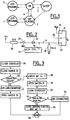
- Figure 1 is a representation of the state machine of a computer of the type currently sold by the applicant under the reference (reference to be completed).
- the computer may be in five different states. In the first one 1, the computer is off and unplugged, and the power consumption is nil; in a second state 2, the computer is OFF; in this state, the power supply unit is connected to the power supply, and the computer is off.
- the LAN card of the computer is in a sleep mode, that is the LAN is not available, however, the LAN is always powered and the LAN processor in the LAN card scans networks frames. In this state, pursuant to the German Ecolabel, the power consumption of the computer should be less than 5 W.
- the third state is the ON state, with the computer working; power consumption is then unlimited.
- the fourth state 4 is the sleep mode, where the functionalities of the computer are degraded; in this state, the power supply unit is on, and the computer as well as its LAN card are in a sleep mode. In this fourth state, pursuant to the recommendations of the US Energy Protection Agency, the power consumption should be less than 30 W.
- the fifth state 5 is a state where the computer is plugged and off; this state is entered when there is a power failure while the computer is connected to the wall.
- the computer passes from the second state to the third one, as symbolised by arrow 6 when the ON/OFF button of the computer is activated to switch the computer on.
- the computer passes from the fourth state - sleep mode - to the third state - ON - when the computer is woken up. This may for instance be the case when the user presses a key on the keyboard of the computer.
- Remote Power-on is the ability to power-on a PC remotely, from the OFF state
- remote wake-up is the ability to wake-up a PC from energy saving sleep mode.
- One LAN card allowing RPO and RWU is the PRO/100 LAN card sold by Intel which includes Wake on Lan capability.
- a WOL connector from the LAN card to the motherboard of the computer.
- the WOL connector comprises three pins: ground and power (Vccaux) pins, and one pin for a wake signal.
- Other manufacturers have the same or similar connectors for providing power from the motherboard, for instance Hewlett-Packard provides on some of its personal computers a NightDirector connector that comprises 5 RPO/RWU related pins, that is ground and power (Vccaux) pins, together with a power on pin, a wake-up pin and a RPO enable pin.
- a PC motherboard may comprise more than one socket to accommodate different types of connectors.
- WOL connector will be used to refer both to the Wake on Lan connector (and socket) available from IBM or Intel and to similar connectors or sockets incorporated in the products of other manufacturers.
- the power supply unit of the computer is switched off, and the main power supply Vcc of the computer is down.
- the auxiliary power supply Vaux or Vtrickle is available; this auxiliary power supply is used to power the LAN card, through the WOL socket, or through the HP NightDirector socket.
- the LAN card may method incoming frames, and the controller may wake-up or power-on the computer.
- a computer comprises more than one LAN cards, and if both cards enable RPO and RWU, more than one motherboard socket - for instance the WOL socket and the HP NightDirector socket - may be provided.
- the power supply to the auxiliary power supply may not be sufficient for powering each of the cards.
- the available current on Vaux is usually limited to 700 mA. This problem is explained for instance in the user manual or in the Bios setup of computers sold by the applicant under the reference HP VECTRA VL8. The same problem also exists for any other specification using Vccaux ; this is for instance the case for PCI 2.2.
- the invention provides a solution to this problem. It ensures that the power consumption of the LAN cards in the computer in the sleep state will remain below the available power.
- the invention provides a solution to the problem of detecting the presence of a WOL connector in a computer. Such a detection may also be useful for purpose other than power management in sleep states.
- a method for detecting the presence of a connector in a socket, said connector keeping a pin of the socket to a a given level comprising the steps of
- the invention also provides a method for disabling one of two sockets in a computer board, comprising the steps of:
- the invention provides a computer board, comprising a socket for receiving a connector, means for temporarily pulling one pin of said socket to a level, and means for determining the level on said pin.
- the means for temporarily pulling comprise a resistor and a switch connected in series between said pin and said a level.
- the pin is wired to a register of a controller, and the means for determining comprises means for scanning said register.
- the socket is in the motherboard of a computer, and is provided for receiving a connector to a local area network card.
- the pin is a wake-up signal pin.
- FIG. 2 is a schematic diagram of a circuit according to one embodiment of the invention.
- the diagram of figure 2 shows the WOL socket 10 of the motherbord, with its Vaux, ground and wake pins 11, 12 and 13.
- the Vaux pin is wired to the Vaux plane
- the ground pin is wired to the ground plane.
- the wake signal pin is wired by wire 15 to one pin 16 of the controller 17, e.g. one pin of an Advanced Configuration and Power Interface (ACPI) controller, for setting the status bit of the wake-up event.
- ACPI is an open interface specification defined by Intel, Microsoft and Toshiba which specifies the power management interface between a computer operating system and the system hardware and software that enables the operating system to manage the power consumption of the computer.
- the ACPI 1.0 Specification available from Microsoft can be consulted for more details .
- wire 15 is connected to the ground through a resistor 18, usually a 10 kOhms resistor, that pulls down the wake pin.
- the WOL socket does not comprise any pin that could be used for detecting the presence of a connected card.
- the invention proposes to provide a pull-upon the wire 15, having a lower resistance than that of the pull-down resistor 18. This pull-up is controlled by a switch.
- the wire 15 is connected to the main power supply Vcc through a resistor 20, a switch 21, and a diode 22.
- the resistor 20 has a resistance lower than the pull-down resistor 18, e. g. a resistance of 1 kOhm.
- the switch 21 is controlled by the Bios of the computer.
- Diode 22 ensures that the Vaux pin of the WOL connector sends current to Vcc when the computer is off.
- the operation of the circuit of figure 2 is described in the flowchart of figure 3; it is carried out in a state where the power supply to the pull-up is provided.
- the ACPI status bit is cleared ; indeed, the ACPI status bits are 'sticky', that is they remain in the high level even if the event that generated them has disappeared.
- the switch 21 is closed, under a command of the Bios, for a period of time sufficient to pull-up wire 15 where no connector is plugged into the socket. For the exemplified values of resistance of the pull-up and pull-down resistors, a period of time of 1 ms is sufficient.
- an inquiry on the status bit of the ACPI controller is conducted.
- step 27 If the status bit is at a low level, step 27, the pull-up did not succeed in pulling the wake-up pin to the high level. This means that a LAN card is connected to the WOL socket, and that the buffer of the LAN card has kept the wake-up signal at a low level, notwithstanding the pull-up. It is then determined that a LAN card is connected to the WOL socket.
- step 28 it is determined that no connector is plugged into the socket, or that a connector plugged into the socket asserts a high level on the pin. Operation then passes to step 31 ; in this step, the switch 21 is opened, and then, at step 32, the status bit is again cleared. Thereafter, in step 33, another inquiry on the status bit of the ACPI controller is conducted. If the status bit is 0, step 34, it is determined that there is no connector plugged, and the operation is ended. Else, in step 35, if the status bit is at a high level, it is determined that a card is present, and drives the Vaux of the WOL connector to a high level. The process is then over.
- step 27 the pull-up switch is opened, step 29. Thereafter, step 30, the process according to the invention is over; it may be repeated at any time. It should be noted that the step of opening the switch may also be carried out at a different time, e. g. 1 ms or so before scanning the status bit.
- the step of inquiry of the value of the status bit is conducted after a period of time that is short with respect to the time constant of the buffer and pull-up assembly; this ensures that the value of the status bit will be very near to the low level imposed by the buffer of the LAN card.
- the period of time is also preferably longer than the time constant of the wire and pull-up assembly; thus, if no LAN card is connected to the socket, the value of the status bit will reach the high level before it is scanned. A time period of 1 ms is appropriate.
- This approach may be used as a solution to the above mentioned problem of powering of LAN cards in the sleep states of the computer. For this purpose, if the presence of a WOL connector plugged into the WOL socket is detected, the HP NightDirector socket is disabled, at least in the sleep states. This may be done by methods known per se to the person skilled in the art, e.g. using the Bios.
- both the HP NightDirector socket and a PCI 2.2 socket have the feature that they may be disabled, whereas the WOL socket may not be disabled. If the HP NightDirector socket is disabled when the presence of a WOL connector is detected it is ensured that the HP NightDirector socket will not be powered, and that the power consumption in the sleep states will stay below the authorised consumption.
- the invention is not limited to the embodiments discussed above. It applies not only for disabling a HP NightDirector socket or a PCI 2.2 socket, but also for any purpose where the detection of the presence of a WOL connector in a WOL socket is necessary. More generally the same approach may be applied to the detection of a connector in a socket, when a pin is kept by the connector at a given level. It this case, the pull-up represents means for pulling the pin to the other level.
- the invention has been described in relation to the preferred embodiment, where the WOL connector keeps the wake signal at a low level; however, the invention may be equally well carried out for detecting a connector that keeps a pin at a high level. In this case, the role of the ground and of the Vcc voltage will simply be exchanged.
- socket and connector are used throughout this specification to designate two mating parts.
- pin is used to designate one means of providing electrical connection in the socket or connector.
- the invention is unrelated to the nature and structure of the socket and connector assembly, and may be carried out for any type of such assembly; it is also unrelated to the way the pin of the socket and connector are put into contact.
- the term "pin" is intended to cover any alternative contact portion in the connector, male or female.
Landscapes
- Physics & Mathematics (AREA)
- General Physics & Mathematics (AREA)
- Engineering & Computer Science (AREA)
- Theoretical Computer Science (AREA)
- General Engineering & Computer Science (AREA)
- Power Sources (AREA)
Priority Applications (3)
| Application Number | Priority Date | Filing Date | Title |
|---|---|---|---|
| DE69836677T DE69836677D1 (de) | 1998-06-08 | 1998-06-08 | Verfahren und Schaltungskreis zur Erfassung der Anwesenheit eines Verbindungsteils in einer Kontaktbuchse |
| EP98401426A EP0964255B1 (de) | 1998-06-08 | 1998-06-08 | Verfahren und Schaltungskreis zur Erfassung der Anwesenheit eines Verbindungsteils in einer Kontaktbuchse |
| US09/327,263 US6477602B1 (en) | 1998-06-08 | 1999-06-07 | Method and circuit for detecting the presence of a connector in a socket |
Applications Claiming Priority (1)
| Application Number | Priority Date | Filing Date | Title |
|---|---|---|---|
| EP98401426A EP0964255B1 (de) | 1998-06-08 | 1998-06-08 | Verfahren und Schaltungskreis zur Erfassung der Anwesenheit eines Verbindungsteils in einer Kontaktbuchse |
Publications (2)
| Publication Number | Publication Date |
|---|---|
| EP0964255A1 true EP0964255A1 (de) | 1999-12-15 |
| EP0964255B1 EP0964255B1 (de) | 2006-12-20 |
Family
ID=8235403
Family Applications (1)
| Application Number | Title | Priority Date | Filing Date |
|---|---|---|---|
| EP98401426A Expired - Lifetime EP0964255B1 (de) | 1998-06-08 | 1998-06-08 | Verfahren und Schaltungskreis zur Erfassung der Anwesenheit eines Verbindungsteils in einer Kontaktbuchse |
Country Status (3)
| Country | Link |
|---|---|
| US (1) | US6477602B1 (de) |
| EP (1) | EP0964255B1 (de) |
| DE (1) | DE69836677D1 (de) |
Families Citing this family (14)
| Publication number | Priority date | Publication date | Assignee | Title |
|---|---|---|---|---|
| JP4383641B2 (ja) * | 2000-08-31 | 2009-12-16 | 株式会社東芝 | 表示制御装置およびコンピュータシステム並びにパワーマネージメント方法 |
| JP4407042B2 (ja) * | 2000-11-15 | 2010-02-03 | パナソニック株式会社 | 情報処理装置 |
| US7120720B1 (en) * | 2001-11-01 | 2006-10-10 | Advanced Micro Devices, Inc. | Microcomputer bridge for remote manageability |
| US20050270993A1 (en) * | 2004-06-07 | 2005-12-08 | Krishnan Rajamani | Efficient partitioning of MAC (media access control) functions |
| US7614737B2 (en) * | 2005-12-16 | 2009-11-10 | Lexmark International Inc. | Method for identifying an installed cartridge |
| CN2909367Y (zh) * | 2005-12-30 | 2007-06-06 | 鸿富锦精密工业(深圳)有限公司 | 主板供电保护电路 |
| US20080258704A1 (en) * | 2007-04-23 | 2008-10-23 | Ryskoski Matthew S | Method and apparatus for identifying broken pins in a test socket |
| US7814370B2 (en) * | 2007-12-17 | 2010-10-12 | Inventec Corporation | Wake on LAN (WOL) test system and method thereof |
| DE102008003986B3 (de) * | 2008-01-11 | 2009-08-27 | Fujitsu Siemens Computers Gmbh | Mainboard, elektronisches Gerät sowie Anordnung eines elektronischen Gerätes mit einer Spannungsversorgungseinheit |
| EP2240000A1 (de) | 2009-04-08 | 2010-10-13 | Nxp B.V. | Meldungssteuerbare Lampe |
| CN102141593B (zh) * | 2010-12-24 | 2013-06-05 | 华为终端有限公司 | 用于检测射频接口外插连接的检测装置和方法 |
| CN102809722A (zh) * | 2011-05-30 | 2012-12-05 | 鸿富锦精密工业(深圳)有限公司 | 唤醒信号测试系统及其测试卡 |
| US20230118452A1 (en) * | 2020-07-06 | 2023-04-20 | Mitsubishi Electric Corporation | Input/output module, standard input/output module unit, and safety circuit unit |
| EP4425842A1 (de) | 2023-03-03 | 2024-09-04 | Rohde & Schwarz GmbH & Co. KG | Über aufwecknetzwerkfunktionen aktivierbare messvorrichtung |
Citations (4)
| Publication number | Priority date | Publication date | Assignee | Title |
|---|---|---|---|---|
| GB2203560A (en) * | 1987-04-18 | 1988-10-19 | Heidelberger Druckmasch Ag | Testing electric cable connections |
| JPH01289077A (ja) * | 1988-05-17 | 1989-11-21 | Mitsubishi Electric Corp | コネクター |
| DE4243348A1 (de) * | 1992-12-21 | 1994-06-23 | Siemens Ag | Anordnung mit steckbaren Funktionseinheiten |
| JPH09258866A (ja) * | 1996-03-22 | 1997-10-03 | Oki Electric Ind Co Ltd | Scsiターミネータ |
Family Cites Families (4)
| Publication number | Priority date | Publication date | Assignee | Title |
|---|---|---|---|---|
| US5870571A (en) | 1996-08-02 | 1999-02-09 | Hewlett-Packard Company | Automatic control of data transfer rates over a computer bus |
| US5862393A (en) * | 1996-10-07 | 1999-01-19 | Lxe, Inc. | System for managing power of a computer with removable devices |
| US5938771A (en) * | 1997-10-30 | 1999-08-17 | Advanced Micro Devices, Inc. | Apparatus and method in a network interface for enabling power up of a host computer using magic packet and on-now power up management schemes |
| US6274949B1 (en) * | 1999-01-18 | 2001-08-14 | Hewlett-Packard Company | Back-up power accessory for a computer |
-
1998
- 1998-06-08 EP EP98401426A patent/EP0964255B1/de not_active Expired - Lifetime
- 1998-06-08 DE DE69836677T patent/DE69836677D1/de not_active Expired - Lifetime
-
1999
- 1999-06-07 US US09/327,263 patent/US6477602B1/en not_active Expired - Fee Related
Patent Citations (4)
| Publication number | Priority date | Publication date | Assignee | Title |
|---|---|---|---|---|
| GB2203560A (en) * | 1987-04-18 | 1988-10-19 | Heidelberger Druckmasch Ag | Testing electric cable connections |
| JPH01289077A (ja) * | 1988-05-17 | 1989-11-21 | Mitsubishi Electric Corp | コネクター |
| DE4243348A1 (de) * | 1992-12-21 | 1994-06-23 | Siemens Ag | Anordnung mit steckbaren Funktionseinheiten |
| JPH09258866A (ja) * | 1996-03-22 | 1997-10-03 | Oki Electric Ind Co Ltd | Scsiターミネータ |
Non-Patent Citations (3)
| Title |
|---|
| "WAKE ON SMARTCARD", IBM TECHNICAL DISCLOSURE BULLETIN, vol. 40, no. 11, November 1997 (1997-11-01), pages 99/100, XP000739934 * |
| PATENT ABSTRACTS OF JAPAN vol. 014, no. 070 (E - 0886) 8 February 1990 (1990-02-08) * |
| PATENT ABSTRACTS OF JAPAN vol. 098, no. 002 30 January 1998 (1998-01-30) * |
Also Published As
| Publication number | Publication date |
|---|---|
| US6477602B1 (en) | 2002-11-05 |
| EP0964255B1 (de) | 2006-12-20 |
| DE69836677D1 (de) | 2007-02-01 |
Similar Documents
| Publication | Publication Date | Title |
|---|---|---|
| EP0964255B1 (de) | Verfahren und Schaltungskreis zur Erfassung der Anwesenheit eines Verbindungsteils in einer Kontaktbuchse | |
| US8150539B2 (en) | Information processing apparatus and method for controlling power supply of the apparatus | |
| US6321340B1 (en) | Cable manager system and computer therewith | |
| US7320077B2 (en) | Power supply controlling apparatus of a device connected to a serial bus | |
| US7454641B2 (en) | System powered from a local area network cable | |
| JP3074230U (ja) | コンピュータ用電源のセキュリティ制御装置 | |
| CN100583004C (zh) | 一种计算机atx电源的控制装置及其控制方法 | |
| US5944831A (en) | Power management apparatus and method for managing power application to individual circuit cards | |
| US20090307505A1 (en) | Sensing Socket Assembly | |
| EP2109804B1 (de) | Verfahren und systeme zur steuerung der leistung eines computersystems | |
| US7461277B2 (en) | Image forming device, power supply control device | |
| JP4416715B2 (ja) | ネットワークインタフェース電源管理のシステムおよび方法 | |
| CN100454817C (zh) | 基于网络的计算机远程唤醒方法与装置 | |
| JPH11102253A (ja) | ペン入力情報処理装置、ペン入力情報処理装置の制御回路及びペン入力情報処理装置の制御方法 | |
| JP2000122756A (ja) | 電子機器 | |
| JPH11191026A (ja) | 電源及びハードウェア障害の切り分け装置及びその方法 | |
| JP3063838U (ja) | 自動省電睡眠機能を具えたpcカ―ド | |
| JP2001337752A (ja) | ホスト装置の周辺デバイス | |
| US20060152381A1 (en) | Detection of connection and disconnection of computer peripheral | |
| US6671750B2 (en) | LAN interface | |
| CN1991686B (zh) | 计算机电源管理装置及方法 | |
| EP1132803A1 (de) | Elektronische vorrichtung, kontrollkreislauf für elektronische vorrichtung und verfahren zur kontrolle elektronischer vorrichtung | |
| CN101826684B (zh) | 一种电源插板装置及其控制方法 | |
| JPH0566867A (ja) | 拡張システム | |
| CN217061038U (zh) | 供电电路系统以及人脸识别设备 |
Legal Events
| Date | Code | Title | Description |
|---|---|---|---|
| PUAI | Public reference made under article 153(3) epc to a published international application that has entered the european phase |
Free format text: ORIGINAL CODE: 0009012 |
|
| AK | Designated contracting states |
Kind code of ref document: A1 Designated state(s): DE FR GB IT NL |
|
| AX | Request for extension of the european patent |
Free format text: AL;LT;LV;MK;RO;SI |
|
| 17P | Request for examination filed |
Effective date: 20000615 |
|
| AKX | Designation fees paid |
Free format text: DE FR GB IT NL |
|
| RAP1 | Party data changed (applicant data changed or rights of an application transferred) |
Owner name: HEWLETT-PACKARD COMPANY, A DELAWARE CORPORATION |
|
| 17Q | First examination report despatched |
Effective date: 20040429 |
|
| GRAP | Despatch of communication of intention to grant a patent |
Free format text: ORIGINAL CODE: EPIDOSNIGR1 |
|
| RIC1 | Information provided on ipc code assigned before grant |
Ipc: G06F 1/22 20060101ALI20060613BHEP Ipc: G01R 31/04 20060101AFI20060613BHEP |
|
| GRAS | Grant fee paid |
Free format text: ORIGINAL CODE: EPIDOSNIGR3 |
|
| GRAA | (expected) grant |
Free format text: ORIGINAL CODE: 0009210 |
|
| AK | Designated contracting states |
Kind code of ref document: B1 Designated state(s): DE FR GB IT NL |
|
| PG25 | Lapsed in a contracting state [announced via postgrant information from national office to epo] |
Ref country code: NL Free format text: LAPSE BECAUSE OF FAILURE TO SUBMIT A TRANSLATION OF THE DESCRIPTION OR TO PAY THE FEE WITHIN THE PRESCRIBED TIME-LIMIT Effective date: 20061220 Ref country code: IT Free format text: LAPSE BECAUSE OF FAILURE TO SUBMIT A TRANSLATION OF THE DESCRIPTION OR TO PAY THE FEE WITHIN THE PRESCRIBED TIME-LIMIT;WARNING: LAPSES OF ITALIAN PATENTS WITH EFFECTIVE DATE BEFORE 2007 MAY HAVE OCCURRED AT ANY TIME BEFORE 2007. THE CORRECT EFFECTIVE DATE MAY BE DIFFERENT FROM THE ONE RECORDED. Effective date: 20061220 |
|
| REG | Reference to a national code |
Ref country code: GB Ref legal event code: FG4D |
|
| REF | Corresponds to: |
Ref document number: 69836677 Country of ref document: DE Date of ref document: 20070201 Kind code of ref document: P |
|
| PG25 | Lapsed in a contracting state [announced via postgrant information from national office to epo] |
Ref country code: DE Free format text: LAPSE BECAUSE OF FAILURE TO SUBMIT A TRANSLATION OF THE DESCRIPTION OR TO PAY THE FEE WITHIN THE PRESCRIBED TIME-LIMIT Effective date: 20070321 |
|
| NLV1 | Nl: lapsed or annulled due to failure to fulfill the requirements of art. 29p and 29m of the patents act | ||
| EN | Fr: translation not filed | ||
| PLBE | No opposition filed within time limit |
Free format text: ORIGINAL CODE: 0009261 |
|
| STAA | Information on the status of an ep patent application or granted ep patent |
Free format text: STATUS: NO OPPOSITION FILED WITHIN TIME LIMIT |
|
| PGFP | Annual fee paid to national office [announced via postgrant information from national office to epo] |
Ref country code: GB Payment date: 20070628 Year of fee payment: 10 |
|
| 26N | No opposition filed |
Effective date: 20070921 |
|
| PG25 | Lapsed in a contracting state [announced via postgrant information from national office to epo] |
Ref country code: FR Free format text: LAPSE BECAUSE OF FAILURE TO SUBMIT A TRANSLATION OF THE DESCRIPTION OR TO PAY THE FEE WITHIN THE PRESCRIBED TIME-LIMIT Effective date: 20070810 |
|
| PG25 | Lapsed in a contracting state [announced via postgrant information from national office to epo] |
Ref country code: FR Free format text: LAPSE BECAUSE OF FAILURE TO SUBMIT A TRANSLATION OF THE DESCRIPTION OR TO PAY THE FEE WITHIN THE PRESCRIBED TIME-LIMIT Effective date: 20061220 |
|
| GBPC | Gb: european patent ceased through non-payment of renewal fee |
Effective date: 20080608 |
|
| PG25 | Lapsed in a contracting state [announced via postgrant information from national office to epo] |
Ref country code: GB Free format text: LAPSE BECAUSE OF NON-PAYMENT OF DUE FEES Effective date: 20080608 |