EP0964271A2 - Antenne remorquée sous-marin - Google Patents
Antenne remorquée sous-marin Download PDFInfo
- Publication number
- EP0964271A2 EP0964271A2 EP99108389A EP99108389A EP0964271A2 EP 0964271 A2 EP0964271 A2 EP 0964271A2 EP 99108389 A EP99108389 A EP 99108389A EP 99108389 A EP99108389 A EP 99108389A EP 0964271 A2 EP0964271 A2 EP 0964271A2
- Authority
- EP
- European Patent Office
- Prior art keywords
- tow
- cavities
- pump elements
- hose
- towing
- Prior art date
- Legal status (The legal status is an assumption and is not a legal conclusion. Google has not performed a legal analysis and makes no representation as to the accuracy of the status listed.)
- Withdrawn
Links
Images

Classifications
-
- G—PHYSICS
- G01—MEASURING; TESTING
- G01V—GEOPHYSICS; GRAVITATIONAL MEASUREMENTS; DETECTING MASSES OR OBJECTS; TAGS
- G01V1/00—Seismology; Seismic or acoustic prospecting or detecting
- G01V1/16—Receiving elements for seismic signals; Arrangements or adaptations of receiving elements
- G01V1/20—Arrangements of receiving elements, e.g. geophone pattern
- G01V1/201—Constructional details of seismic cables, e.g. streamers
Definitions
- the invention relates to an underwater towing antenna genus defined in the preamble of claim 1.
- Tow antennas for sonar tracking purposes usually performed without a trim device and before Lay out with a preferred liquid buoyancy filled that because of its filling quantity and its physical properties buoyancy neutrality of the Tow strand in the desired layout or Tows the towing antenna. That changes Field of application, e.g. at the transition from the North to the Baltic Sea, see above As a rule, the physical ones also change Properties of sea water, e.g. its density, the Salinity, temperature, etc. Then the desired one To reach water depth again, the trailing antenna must hauled in and buoyant on board or be drained or the buoyancy agent through a other be replaced. Such a conversion of the Towing antenna is a complex procedure and takes Hours.
- the invention has for its object in a Underwater towing antenna of the type mentioned Trimming the towline at least in a limited way Depth stroke range of the trailing antenna is much easier, faster and more effective and the necessary Trimmer to design cheaper.
- the task is with an underwater towing antenna type mentioned by the features in the claim 1 solved.
- the underwater towing antenna according to the invention has the Advantage that the pump elements with an integrated cavity are technically robust and quite inexpensive components, so that the trimmer at low cost is available.
- the building blocks are within the Dragline hose arranged and thus hinder not inserting and removing the trailing antenna.
- flooding and draining of the cavities Diving depth can be varied, but also by different degrees of draining and flooding over the Dragline distributed cavities precisely of the acoustic sector of the towline in horizontal Direction can be achieved so that the required accuracy acoustic location can be easily reached.
- the pump elements and Cavities the possibility of the acoustic sector too at an acute angle at an angle to the towing direction hire in which the front and rear cavities flooded or drained more and the intermediate cavities adjusted accordingly Water to be filled.
- an inclined acoustic section with continuously varied Helix angle can also be the depth of a dive measured localized acoustic sound source, resulting in the use profile of the underwater towing antenna clearly improved.
- the trimming device according to the invention can both with conventional underwater towing antennas, so-called Towed arrays, with an elastic tube as well So-called digital arrays with a rigid tube body, however also due to the smallness of the pump elements, with so-called Thinline arrays with an outside diameter of less than 3 cm can be used.
- FIG. 1 in a schematic side view and in FIG. 2 the enlarged underwater tow antenna can be seen consists of a tow 10 and a Trailing cable 11, the tow 10 with a Towing vehicle 12 connects.
- the towing vehicle 12 is shown here as a surface ship, but can also be a Be a submarine.
- the trailing cable 11 is on the one side Winding drum 13 attached to which both Trailing cable 11 and the tow 10 are wound can be.
- the tow 10 is by means of a plug 14, the both mechanical and electrical Establishes connection, connected to the trailing cable 11 and carries a drag brake at its opposite end 15, which when towing for a certain tension on Tow strand 10 provides against the towing direction.
- acoustic section 16 which between two damping modules 17, 18, so-called VIMs (vibration Isolation module).
- the front one Damping module 17 connects the acoustic section 16 with the trailing cable 11, while the rear damping module 18 the drag brake 15 to the acoustic section 16 couples. Both damping modules 17, 18 are used for acoustic decoupling of acoustic section 16 against the impact and vibration noises of the Drag cable 11 or the drag brake 15.
- the acoustic Section 16 which is known from a variety of spaced hydrophones, not shown here is arranged in an elastic hose 20, with a buoyancy means 21 (Fig. 3), e.g. Oil or Gel that is filled.
- the two damping modules 17, 18 are filled with the buoyancy 21 Hose sections formed at the interfaces 22, 23 (Fig. 2) to the hose 20 with the acoustic section 16 are coupled.
- FIG. 3 runs through on the one hand a pull rope 24 and on the other hand Harness 25 the entire hose 20 and also the Hose sections 201, 202 of the damping modules 17, 18.
- Das Traction rope 24 serves to accommodate the tow 10 attacking tensile force and the wiring harness 25 for electricity and Data transmission between the hydrophones and others electronic components in tow 10 for Towing vehicle 12. That in acoustic section 16 and buoyancy means contained in the damping modules 17, 18 21 is regarding its filling quantity and physical Properties designed so that the entire tow strand 10 buoyancy neutrality in a desired water depth having.
- the tow 10 is with a trimmer equipped from a variety of selected Place the tow 10 within the hose 20 and the hose sections 201, 202 of the damping modules 17, 18 arranged cavities 26 and the cavities 26 associated electrically driven pump elements 27 having.
- By flooding and draining the over Trailing strand 10 distributed cavities 26 with Water from the towline environment can both Diving depth of the tow 10 can be varied as well the hose 20 with the acoustic section 16 exactly aligned horizontally and without sagging.
- a such linear alignment of the hydrophones of the acoustic Section 16 significantly improves the location results of the Towing antenna.
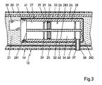
- the cavities are 26 integrated in the pump elements 27, wherein Fig. 3 in Longitudinal section an embodiment of such Pump element 27 with integrated cavity 26 shows.
- the Pump element 27 has a working cylinder 28 with a therein axially displaceably guided working piston 29, which is linearly driven by an electric motor 30.
- Electric motor 30 is on the outside on one end face 281 of the Working cylinder 28 flanged and drives in a transmission housing 31 received a Threaded spindle 32, which is in the working cylinder 28 axially extends and on the other end of the Working cylinder 28 rotatable in the cylinder wall 282 is stored.
- On the threaded spindle 32 is the Working piston 29 screwed to an internal thread 33.
- gas and liquid tight sealed working piston 29 divides the Working cylinder 28 in two cylinder chambers 35, 36 with at the piston displacement inversely changing Chamber volumes, of which the cylinder chamber 35 with a Compensation chamber 41 and the other cylinder chamber 36 over a filler neck 37 with the towline environment, that is with the water.
- the cylinder chamber 36 forms the integrated cavity 26 of the trimming device, and the compensation chamber 41, which is in the working cylinder 28 is integrated and with the cylinder chamber 35 a hermetic closed system is with air or an oil filled, the specific weight of which is significantly less than Is water.
- the compensation chamber 41 is through a Limit stop 39 for the working piston 29 limited.
- Oil filled that's how it should be Pump element 27, that is, the working cylinder 28, opposite the hose 20 supported and on the pull rope 24 against axial Displacement to be fixed.
- the two end stops 39, 40 are in the embodiment as radially projecting from the cylinder inner wall 283 Ring bars executed.
- the electric motor 30 provided with a limit switch that the electric motor 30th switches off automatically as soon as the working piston 29 is on one of its end stops 39, 40 abuts.
- the air-filtered rooms such as Cylinder chambers 35, 36 and compensation chamber 41, too prevent, the entire cylinder 28 of one Layer 42 encased in an absorber material.
- Pressure sensor can be arranged, which detects the actual pressure value and delivers to the control circuit.
- the control circuit is now designed so that the pump elements 27 so long controlled until even drainage or flooding of all Cavities 26 in the pump elements 27 of the pressure sensor measured actual pressure value the specified target pressure value corresponds.
- the trimmer can also be used for the Location of sound sources in the water additional Information, so information about the exact depth the source of sound. for this are from the Control circuit the individual over the tow 10 distributed pump elements 27 so that e.g. the Cavities 26 from the beginning of the strand to the end of the strand constantly increasing water volume can be filled. Thereby the tow 10 has one from the beginning of the strand Stranded decreasing buoyancy and the acoustic section 16 takes an oblique position, which is under a pointed one Angle to the towing direction.
- Continuous carried out change of the angle of inclination of the acoustic Section 16 in the range greater than 0 ° and less than 90 ° opposite the vertical can by means of the over the individual Hydrophones received acoustic signals based on the Intensity of the received signals and the current one Angle of attack of the acoustic section 16 the depth of the located sound source can be determined.
- the acoustic section at a constant angle of inclination employed and by means of the so-called beamforming Reception lobe of the acoustic section, i.e. the Receiving direction pivoted with the greatest sensitivity become. Based on the intensity of the received signals, the Direction of reception and the known recruitment or The angle of inclination of the acoustic section is again the Depth of a sound source can be determined.
Landscapes
- Physics & Mathematics (AREA)
- Life Sciences & Earth Sciences (AREA)
- Engineering & Computer Science (AREA)
- Acoustics & Sound (AREA)
- Environmental & Geological Engineering (AREA)
- Geology (AREA)
- Remote Sensing (AREA)
- General Life Sciences & Earth Sciences (AREA)
- General Physics & Mathematics (AREA)
- Geophysics (AREA)
- Measurement Of Velocity Or Position Using Acoustic Or Ultrasonic Waves (AREA)
- Transducers For Ultrasonic Waves (AREA)
Applications Claiming Priority (2)
| Application Number | Priority Date | Filing Date | Title |
|---|---|---|---|
| DE19825887 | 1998-06-10 | ||
| DE1998125887 DE19825887A1 (de) | 1998-06-10 | 1998-06-10 | Unterwasser-Schleppantenne |
Publications (2)
| Publication Number | Publication Date |
|---|---|
| EP0964271A2 true EP0964271A2 (fr) | 1999-12-15 |
| EP0964271A3 EP0964271A3 (fr) | 2000-07-05 |
Family
ID=7870493
Family Applications (1)
| Application Number | Title | Priority Date | Filing Date |
|---|---|---|---|
| EP99108389A Withdrawn EP0964271A3 (fr) | 1998-06-10 | 1999-04-29 | Antenne remorquée sous-marin |
Country Status (2)
| Country | Link |
|---|---|
| EP (1) | EP0964271A3 (fr) |
| DE (1) | DE19825887A1 (fr) |
Cited By (6)
| Publication number | Priority date | Publication date | Assignee | Title |
|---|---|---|---|---|
| WO2003027712A2 (fr) | 2001-09-27 | 2003-04-03 | Westerngeco L.L.C. | Procede et dispositif de reglage dynamique de la flottabilite de reseaux remorques |
| WO2015128221A1 (fr) * | 2014-02-27 | 2015-09-03 | Rolls-Royce Marine As | Flotteur flexible pour source sismique en mer |
| US9222350B2 (en) | 2011-06-21 | 2015-12-29 | Diamond Innovations, Inc. | Cutter tool insert having sensing device |
| CN110406637A (zh) * | 2019-07-18 | 2019-11-05 | 天津大学 | 基于无人船的细小型声呐阵列进行姿态转换的方法和装置 |
| CN113405645A (zh) * | 2021-06-08 | 2021-09-17 | 哈尔滨工程大学 | 一种基于活塞的耐静水压光纤水听器 |
| DE102021208106A1 (de) | 2021-07-27 | 2023-02-02 | Atlas Elektronik Gmbh | Schleppantenne mit einem Drucksensor |
Families Citing this family (1)
| Publication number | Priority date | Publication date | Assignee | Title |
|---|---|---|---|---|
| DE102012008248A1 (de) | 2011-12-20 | 2013-06-20 | Atlas Elektronik Gmbh | Kupplungsmittel für Schlauchantennen sowie Unterwasserantenne mit derartigem Kupplungsmittel |
Family Cites Families (4)
| Publication number | Priority date | Publication date | Assignee | Title |
|---|---|---|---|---|
| US3794965A (en) * | 1972-09-18 | 1974-02-26 | Exxon Production Research Co | Marine seismic cable buoyancy system |
| DE3512946A1 (de) * | 1985-04-11 | 1986-10-16 | Preussag Ag Metall, 3380 Goslar | Vorrichtung zur foerderung von dickstoffsuspensionen und verfahren zu ihrem betrieb |
| US4745583A (en) * | 1986-12-18 | 1988-05-17 | Exxon Production Research Company | Marine cable system with automatic buoyancy control |
| DE4221327C2 (de) * | 1992-06-29 | 2000-08-31 | Thyssen Nordseewerke Gmbh | Tiefenreguliereinheit für einen Außenkabelmantel aufweisende und Hydrophone aufnehmende Unterwassermesskabel |
-
1998
- 1998-06-10 DE DE1998125887 patent/DE19825887A1/de not_active Withdrawn
-
1999
- 1999-04-29 EP EP99108389A patent/EP0964271A3/fr not_active Withdrawn
Cited By (10)
| Publication number | Priority date | Publication date | Assignee | Title |
|---|---|---|---|---|
| WO2003027712A2 (fr) | 2001-09-27 | 2003-04-03 | Westerngeco L.L.C. | Procede et dispositif de reglage dynamique de la flottabilite de reseaux remorques |
| WO2003027712A3 (fr) * | 2001-09-27 | 2003-07-17 | Westerngeco Llc | Procede et dispositif de reglage dynamique de la flottabilite de reseaux remorques |
| AU2002356531B2 (en) * | 2001-09-27 | 2006-09-07 | Westerngeco Seismic Holdings Limited | A method and apparatus for dynamically controlled buoyancy of towed arrays |
| US9222350B2 (en) | 2011-06-21 | 2015-12-29 | Diamond Innovations, Inc. | Cutter tool insert having sensing device |
| WO2015128221A1 (fr) * | 2014-02-27 | 2015-09-03 | Rolls-Royce Marine As | Flotteur flexible pour source sismique en mer |
| CN110406637A (zh) * | 2019-07-18 | 2019-11-05 | 天津大学 | 基于无人船的细小型声呐阵列进行姿态转换的方法和装置 |
| CN113405645A (zh) * | 2021-06-08 | 2021-09-17 | 哈尔滨工程大学 | 一种基于活塞的耐静水压光纤水听器 |
| CN113405645B (zh) * | 2021-06-08 | 2022-09-27 | 哈尔滨工程大学 | 一种基于活塞的耐静水压光纤水听器 |
| DE102021208106A1 (de) | 2021-07-27 | 2023-02-02 | Atlas Elektronik Gmbh | Schleppantenne mit einem Drucksensor |
| DE102021208106B4 (de) * | 2021-07-27 | 2025-09-04 | Atlas Elektronik Gmbh | Schleppantenne mit einem Drucksensor |
Also Published As
| Publication number | Publication date |
|---|---|
| EP0964271A3 (fr) | 2000-07-05 |
| DE19825887A1 (de) | 1999-12-23 |
Similar Documents
| Publication | Publication Date | Title |
|---|---|---|
| DE69523600T2 (de) | Schleppanordnung | |
| DE69906753T2 (de) | System zum gesteuerten senken eines rohres oder kabels | |
| EP3356861B1 (fr) | Ensemble de transducteurs acoustiques, sonar remorqué, treuil, remorqueur et procédé de mise à l'eau et/ou de halage d'un ensemble de transducteurs acoustiques | |
| EP3248033B1 (fr) | Procédé de fabrication d'un câble subaquatique, câble remorqué, sonar remorqué et d'un véhicule aquatique | |
| DE102014215346B4 (de) | Trägersystem für ein Messgerät zum Überwachen eines Wasserbauwerks unter Wasser | |
| WO2023011925A1 (fr) | Véhicule sous-marin et procédé pour améliorer l'image de position d'un véhicule sous-marin | |
| EP0964271A2 (fr) | Antenne remorquée sous-marin | |
| WO2006072302A1 (fr) | Dispositif et procede de suivi d'un sous-marin | |
| DE2109532B2 (de) | Unterwassermesswindensystem | |
| DE102010004548B4 (de) | Verfahren zum Betrieb eines hydraulischen Systems eines Unterseebootes und Unterseeboot mit einer Hydraulikanlage zur Durchführung des Verfahrens | |
| EP3917827B1 (fr) | Dispositif d'habillage d'un récepteur de sons sous-marins | |
| DE2404871A1 (de) | System zur gewaesserueberwachung | |
| DE102018203601A1 (de) | Verfahren und Vorrichtung zur Schweberegelung für ein Unterwasserfahrzeug | |
| EP1879041B1 (fr) | Dispositif d'enregistrement et de localisation d'émissions de bruits | |
| DE102020206996A1 (de) | Tiefenvariables Schleppsonar sowie Verfahren zum Betreiben | |
| WO2010040569A1 (fr) | Hydrophone et dispositif à hydrophone pour l'exécution d'enregistrements stéréophoniques sous l'eau | |
| DE102021208106B4 (de) | Schleppantenne mit einem Drucksensor | |
| DE102016003926B4 (de) | Unterwasser-Messsonde | |
| DE4221327C2 (de) | Tiefenreguliereinheit für einen Außenkabelmantel aufweisende und Hydrophone aufnehmende Unterwassermesskabel | |
| DE102005006430B4 (de) | Unbemanntes Unterwasserfahrzeug | |
| EP0964264A2 (fr) | Procédé pour déterminer la profondeur de sources acoustiques immergées | |
| EP1033588B1 (fr) | Antenne remorquée | |
| DE102004062126A1 (de) | Unbemanntes Unterwasserfahrzeug | |
| DE10041928A1 (de) | Unterwasserantenne | |
| DE102012206843A1 (de) | Wasserfahrzeug mit bionischem Antrieb |
Legal Events
| Date | Code | Title | Description |
|---|---|---|---|
| PUAI | Public reference made under article 153(3) epc to a published international application that has entered the european phase |
Free format text: ORIGINAL CODE: 0009012 |
|
| AK | Designated contracting states |
Kind code of ref document: A2 Designated state(s): AT BE CH CY DE DK ES FI FR GB GR IE IT LI LU MC NL PT SE |
|
| AX | Request for extension of the european patent |
Free format text: AL;LT;LV;MK;RO;SI |
|
| PUAL | Search report despatched |
Free format text: ORIGINAL CODE: 0009013 |
|
| AK | Designated contracting states |
Kind code of ref document: A3 Designated state(s): AT BE CH CY DE DK ES FI FR GB GR IE IT LI LU MC NL PT SE |
|
| AX | Request for extension of the european patent |
Free format text: AL;LT;LV;MK;RO;SI |
|
| RIC1 | Information provided on ipc code assigned before grant |
Free format text: 7G 01V 1/38 A, 7G 01V 1/20 B |
|
| AKX | Designation fees paid | ||
| STAA | Information on the status of an ep patent application or granted ep patent |
Free format text: STATUS: THE APPLICATION IS DEEMED TO BE WITHDRAWN |
|
| 18D | Application deemed to be withdrawn |
Effective date: 20010106 |
|
| REG | Reference to a national code |
Ref country code: DE Ref legal event code: 8566 |