EP0964356A1 - Anordnung zum longitudinalen Blockieren eines starren Datenträgers in einer Datenaustausch-Vorrichtung - Google Patents
Anordnung zum longitudinalen Blockieren eines starren Datenträgers in einer Datenaustausch-Vorrichtung Download PDFInfo
- Publication number
- EP0964356A1 EP0964356A1 EP99401379A EP99401379A EP0964356A1 EP 0964356 A1 EP0964356 A1 EP 0964356A1 EP 99401379 A EP99401379 A EP 99401379A EP 99401379 A EP99401379 A EP 99401379A EP 0964356 A1 EP0964356 A1 EP 0964356A1
- Authority
- EP
- European Patent Office
- Prior art keywords
- locking
- housing
- data carrier
- data
- window
- Prior art date
- Legal status (The legal status is an assumption and is not a legal conclusion. Google has not performed a legal analysis and makes no representation as to the accuracy of the status listed.)
- Granted
Links
Images


Classifications
-
- G—PHYSICS
- G06—COMPUTING OR CALCULATING; COUNTING
- G06K—GRAPHICAL DATA READING; PRESENTATION OF DATA; RECORD CARRIERS; HANDLING RECORD CARRIERS
- G06K13/00—Conveying record carriers from one station to another, e.g. from stack to punching mechanism
- G06K13/02—Conveying record carriers from one station to another, e.g. from stack to punching mechanism the record carrier having longitudinal dimension comparable with transverse dimension, e.g. punched card
- G06K13/08—Feeding or discharging cards
- G06K13/0806—Feeding or discharging cards using an arrangement for ejection of an inserted card
-
- G—PHYSICS
- G06—COMPUTING OR CALCULATING; COUNTING
- G06K—GRAPHICAL DATA READING; PRESENTATION OF DATA; RECORD CARRIERS; HANDLING RECORD CARRIERS
- G06K13/00—Conveying record carriers from one station to another, e.g. from stack to punching mechanism
- G06K13/02—Conveying record carriers from one station to another, e.g. from stack to punching mechanism the record carrier having longitudinal dimension comparable with transverse dimension, e.g. punched card
- G06K13/08—Feeding or discharging cards
-
- G—PHYSICS
- G06—COMPUTING OR CALCULATING; COUNTING
- G06K—GRAPHICAL DATA READING; PRESENTATION OF DATA; RECORD CARRIERS; HANDLING RECORD CARRIERS
- G06K13/00—Conveying record carriers from one station to another, e.g. from stack to punching mechanism
- G06K13/02—Conveying record carriers from one station to another, e.g. from stack to punching mechanism the record carrier having longitudinal dimension comparable with transverse dimension, e.g. punched card
- G06K13/08—Feeding or discharging cards
- G06K13/085—Feeding or discharging cards using an arrangement for locking the inserted card
Definitions
- the present invention relates to an arrangement for the exchange of data between a rigid data medium, or semi-rigid, and a data exchange device, in particular for reading data contained in the medium.
- the invention relates more particularly to such a arrangement intended to equip a motor vehicle and in which data carrier, which is for example in the form of generally rectangular card or badge, door vehicle user identification data which authorize it when he inserts his badge into the reading, to use the vehicle by allowing it to start the vehicle engine.
- data carrier which is for example in the form of generally rectangular card or badge
- door vehicle user identification data which authorize it when he inserts his badge into the reading
- the data carrier is a rigid card or semi-rigid comprising for example an integrated circuit, or chip, which is connected to reading means of the device by electrical contacts and / or by an exchange antenna data.
- the device which receives the card or badge includes means for retaining longitudinally this data carrier in the active position in the housing so that the data exchange is insured in good conditions.
- these means of retainers are constituted by simple brakes, i.e. that they are elastically deformable legs which cooperate by friction with side edges and / or with large sides of the card.
- the invention provides an arrangement for the exchange of data between a rigid data medium, or semi-rigid, and a data exchange device, in particular for reading data contained in the medium, of the type comprising a housing in which the support in general form card is manually inserted into a slot in the housing in which it occupies a determined active position, and of the type in which the device includes means for hold the data carrier longitudinally in position active in the housing, characterized in that the support of data has a window, and in that the case has a support locking lever which is mounted swivels around an axis between a locking position towards which the locking lever is recalled elastically and in which a locking finger formed at the free end of an arm of the locking lever extends vertically inside the window, and a retracted position in which the finger blocking is located outside the window to allow extraction of the storage medium outside the housing.
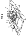
- the arrangement 10 carried out in accordance with the teachings of the invention is consisting mainly of a data carrier or badge 12 and by a housing 14.
- the badge 12 is here a rigid element of general shape rectangular and of reduced thickness which comprises, in the vicinity from its rear transverse edge 16, a gripping part 18.
- the badge 12 is a data carrier which is capable of being introduced longitudinally, i.e. according to direction I parallel to the general plan of its large upper 20 and lower 22 faces, in the housing 14, and which is likely to be extracted from this case according to the same direction but in the opposite direction.
- the case 14, as we can see more particularly in Figures 3 to 5, is constituted for essentially by a central part 24 which constitutes the frame which carries the different components of the case and which is surrounded by a covering part 26.
- the central part 24 essentially consists of two parallel plates upper 28 and lower 30 which vertically define between them a housing 32 of form general parallelepiped rectangle complementary to that of the front part of the badge 12, which is delimited longitudinally forward, i.e. to the right considering the figures, by a transverse abutment face 34 which determines the maximum position for inserting the badge 12 in the housing 14 when the front transverse edge 17 of the badge 12 abuts against this transverse face 34.
- the lower plate 30 carries, under its lower face, a printed circuit board 36 which carries the various electronic circuit components (not shown) belonging to means of order and exchange of data with those contained in badge 12 when it is in its maximum position, also called active position or data exchange.
- the trim part 26 has a slot 38.
- the bottom plate 30 comprises, as can be see in Figures 1 and 2, side rails 40 which cooperate with the opposite longitudinal edges 42 of the badge 12.
- the badge 12 has in its front part a window 44 which extends vertically in the badge and which crosses it here right through go.
- the window 44 has a V trunk profile and is thus delimited by a front transverse edge 46 and by a transverse edge rear 48.
- Window 44 is a blocking window in the sense of the invention, that is to say it is intended to receive a blocking member belonging to the housing 14 and which goes now be described in detail with reference to the figures.
- the badge blocking member 12 in the active position is a locking finger 50 which, in longitudinal section and as can be seen in the figures, presents a V-shaped profile delimited by two inclined front faces 52 and rear 54 which are inclined relative to each other according to substantially the same angle as that formed by edges 46 and 48 of the window 44.
- the locking finger 50 is formed at the free end front 56 of an arm 57 of a locking lever 58 of which the rear end 60 is a cylindrical section which is crossed by an axis 62 of pivoting articulation of the lever 58 so that the latter is pivotally mounted in the two directions around a pivot axis 62 which is perpendicular to the direction of introduction I and parallel to the plane containing the latter, i.e. parallel to the plane general badge 12 when it is inserted in the housing 32.
- the locking lever 58 is resiliently recalled in permanently towards its blocking position, i.e. it is permanently requested clockwise considering Figures 3 to 5, by a return spring 64 which is here a wire spring helically wound around the rear section 60 of the lever 58.
- the locking finger 50 extends opposite a hole 66 formed opposite in the upper plate 28 of the part 24 so that it can extend vertically down to through this hole and inside the housing 52.
- the arrangement also comprises means for locking the locking lever 58 in the locked position.
- the locking means are illustrated diagrammatically under the form of an electromagnet 70 whose movable core (not shown) is likely to order a rod lock or lock finger 72 which is normally partially retracted inside the body of the electromagnet 70 (see Figure 1) and which, in the locked position, protrudes transversely outward, that is to say according to a direction parallel to the axis 62 of the locking lever 58, for extend above an upper face 74 of the end free 56 of the locking lever 58.
- the locking lever 58 When there is no badge 12 in the case 14, the locking lever 58, under the action of spring 64, is in its position illustrated in Figure 3 in which a portion of its lower leg 76 is supported on the upper face of the upper plate 28 and in which the locking finger 50 extends through hole 66 partially inside the housing 32.
- the window 44 is opposite the hole 66 and the locking finger 50.
- the locking finger 50 therefore retains longitudinally in the two way the badge 12 inside the housing 14, that is to say that the latter is not likely to accidentally leave the housing 32 under the action of vibrations, the blocking action resulting from the force applied to the locking lever 58 by the spring 64 being sufficient to counter the consequences harmful vibrations.
- the action of the spring 64 and the finger blocking 50 provides a tactile effect that allows the user to detect a first hard point corresponding to the coming in contact of the front transverse edge 17 with the locking finger 50, then a slight noise followed by an equally noticeable shock when the finger 50 falls into the window 44.
- the front transverse edge 46 of the window 44 cooperates with the front inclined face 52 of the locking finger 50 forming a ramp to cause it to pivot counterclockwise of the locking lever 58 and therefore allow the retraction of the locking finger 50 against the return force applied to the lever 58 by the spring 64 thus ending in first at the position illustrated in Figure 4, then at the position illustrated in Figure 3, the extraction movement can be continued freely until the complete extraction of the badge 12 outside the housing 14.
- the electromagnet 70 with its locking finger 72 may, where appropriate, perform a prohibition function introduction of a badge 12 into the housing 14.
- the invention is particularly applicable on board a motor vehicle whose anti-theft functions are partially or fully insured by processing data, some of which is contained in the medium or badge 12, are representative of an authorized user, or of a group of authorized users of the vehicle.
- Data processing aims in particular to compare the data contained in the badge 12 with data stored on board the vehicle to allow authorized use of the vehicle, the circuit (s) processing ensuring total or partial control of resources forming an anti-theft device, whether it is a conventional anti-theft device, that is to say acting on the steering column of the vehicle, and / or means preventing the vehicle engine from starting and / or interrupting engine operation.
Landscapes
- Physics & Mathematics (AREA)
- General Physics & Mathematics (AREA)
- Engineering & Computer Science (AREA)
- Theoretical Computer Science (AREA)
- Lock And Its Accessories (AREA)
Applications Claiming Priority (2)
| Application Number | Priority Date | Filing Date | Title |
|---|---|---|---|
| FR9807248A FR2779561B1 (fr) | 1998-06-09 | 1998-06-09 | Agencement pour le blocage longitudinal d'un support de donnees rigide dans un dispositif d'echange de donnees |
| FR9807248 | 1998-06-09 |
Publications (2)
| Publication Number | Publication Date |
|---|---|
| EP0964356A1 true EP0964356A1 (de) | 1999-12-15 |
| EP0964356B1 EP0964356B1 (de) | 2008-02-20 |
Family
ID=9527186
Family Applications (1)
| Application Number | Title | Priority Date | Filing Date |
|---|---|---|---|
| EP19990401379 Expired - Lifetime EP0964356B1 (de) | 1998-06-09 | 1999-06-09 | Anordnung zum longitudinalen Blockieren eines starren Datenträgers in einer Datenaustausch-Vorrichtung |
Country Status (4)
| Country | Link |
|---|---|
| EP (1) | EP0964356B1 (de) |
| DE (1) | DE69938162T2 (de) |
| ES (1) | ES2302371T3 (de) |
| FR (1) | FR2779561B1 (de) |
Citations (4)
| Publication number | Priority date | Publication date | Assignee | Title |
|---|---|---|---|---|
| GB2157866A (en) * | 1984-04-18 | 1985-10-30 | Gec Traffic Automation | Shutter arrangements |
| US5043562A (en) * | 1987-10-27 | 1991-08-27 | Mannesmann Kienzle Gmbh | Multi-datacard arrangement |
| EP0447906A2 (de) * | 1990-03-16 | 1991-09-25 | Tamura Plastic Mfg Co., Ltd | Schloss, welches mittels einer Karte mit verschiedenen Löchern betätigbar ist |
| FR2713173A1 (fr) * | 1993-12-03 | 1995-06-09 | Signor Joseph | Véhicule automobile à système de protection vis-à-vis du vol à carte à puce. |
-
1998
- 1998-06-09 FR FR9807248A patent/FR2779561B1/fr not_active Expired - Fee Related
-
1999
- 1999-06-09 DE DE1999638162 patent/DE69938162T2/de not_active Expired - Lifetime
- 1999-06-09 ES ES99401379T patent/ES2302371T3/es not_active Expired - Lifetime
- 1999-06-09 EP EP19990401379 patent/EP0964356B1/de not_active Expired - Lifetime
Patent Citations (4)
| Publication number | Priority date | Publication date | Assignee | Title |
|---|---|---|---|---|
| GB2157866A (en) * | 1984-04-18 | 1985-10-30 | Gec Traffic Automation | Shutter arrangements |
| US5043562A (en) * | 1987-10-27 | 1991-08-27 | Mannesmann Kienzle Gmbh | Multi-datacard arrangement |
| EP0447906A2 (de) * | 1990-03-16 | 1991-09-25 | Tamura Plastic Mfg Co., Ltd | Schloss, welches mittels einer Karte mit verschiedenen Löchern betätigbar ist |
| FR2713173A1 (fr) * | 1993-12-03 | 1995-06-09 | Signor Joseph | Véhicule automobile à système de protection vis-à-vis du vol à carte à puce. |
Also Published As
| Publication number | Publication date |
|---|---|
| DE69938162T2 (de) | 2009-02-26 |
| ES2302371T3 (es) | 2008-07-01 |
| FR2779561A1 (fr) | 1999-12-10 |
| FR2779561B1 (fr) | 2001-01-19 |
| DE69938162D1 (de) | 2008-04-03 |
| EP0964356B1 (de) | 2008-02-20 |
Similar Documents
| Publication | Publication Date | Title |
|---|---|---|
| EP1084915B1 (de) | Kraftfahrzeuglenkungsdiebstahlsicherung | |
| EP0964358B1 (de) | Anordnung zum longitudinalen Blockieren eines Datenträgers in einer Datenaustausch-Vorrichtung | |
| EP1003123B1 (de) | Anordnung zum Blockieren eines Datenträgers in einer Datenaustausch-Vorrichtung | |
| EP0964356B1 (de) | Anordnung zum longitudinalen Blockieren eines starren Datenträgers in einer Datenaustausch-Vorrichtung | |
| EP0964357B1 (de) | Anordnung zum Blockieren eines Datenträgers in einer Datenaustausch-Vorrichtung | |
| EP0995648A1 (de) | Steuersäule-Diebstahlsicherung mit Mittel zur Bolzenverriegelung | |
| EP0989038A1 (de) | Steuersäule-Diebstahlsicherung mit Mittel zur Bolzenverriegelung | |
| EP4177497B1 (de) | Verriegelungsmechanismus | |
| EP0987153B1 (de) | Vorrichtung zur Diebstahlsicherung für eine Lenksäule eines Kraftfahrzeuges mit Befestigungsmittel der Sperrvorrichtung | |
| EP0720760B1 (de) | Chipkartenhalter | |
| EP1467309B1 (de) | Vorrichtung zum Blockieren eines Datenträgers in einem Datenträgerleser | |
| EP1091314B1 (de) | System zur blockierung eines Datenträgers in einer Datenaustauschvorrichtung und zur Motorstartberechtigung eines Fahrzeuges | |
| EP1473659B1 (de) | Anordnung zum Blockieren eines Datenträgers in einer Datenaustausch-Vorrichtung | |
| EP1445729B1 (de) | Anordnung für das Blockieren eines Datenträgers in einer Datenaustauschvorrichtung | |
| EP2439114B1 (de) | Elektrische Diebstahlsicherung zum Verriegeln/Entriegeln einer Lenksäule | |
| EP1091313B1 (de) | System zur Aufnahme eines Datenträgers in einer Datenaustauschvorrichtung mit schwenkbarer Unterstützung | |
| FR2783781A1 (fr) | Antivol de vehicule automobile comportant des moyens perfectionnes de montage et de fixation d'un mecanisme d'antivol | |
| EP2746114B1 (de) | Kontaktschütz für Fahrzeug | |
| FR2793922A1 (fr) | Agencement perfectionne pour le blocage longitudinal d'un support de donnees rigide dans un dispositif d'echange de donnees | |
| FR2793923A1 (fr) | Agencement perfectionne pour le blocage longitudinal d'un support de donnees rigide dans un dispositif d'echange de donnees | |
| EP1043204A1 (de) | Verbesserte Kraftfahrzeugdiebstahlsicherung | |
| FR2717526A1 (fr) | Verrou rotatif comportant des moyens de blocage de la clé en position introduite. | |
| EP1043203A1 (de) | Fahrzeugdiebstahlsicherung | |
| FR2681212A1 (fr) | Systeme de verrouillage pour cartes a circuits imprimes. | |
| EP1158633A1 (de) | Elektrisches Installationsgerät zum Aufschnappen auf eine Tragschiene |
Legal Events
| Date | Code | Title | Description |
|---|---|---|---|
| PUAI | Public reference made under article 153(3) epc to a published international application that has entered the european phase |
Free format text: ORIGINAL CODE: 0009012 |
|
| AK | Designated contracting states |
Kind code of ref document: A1 Designated state(s): DE ES GB IT |
|
| AX | Request for extension of the european patent |
Free format text: AL;LT;LV;MK;RO;SI |
|
| 17P | Request for examination filed |
Effective date: 20000515 |
|
| AKX | Designation fees paid |
Free format text: DE ES GB IT |
|
| RAP1 | Party data changed (applicant data changed or rights of an application transferred) |
Owner name: RENAULT S.A.S. Owner name: VALEO SECURITE HABITACLE |
|
| RAP1 | Party data changed (applicant data changed or rights of an application transferred) |
Owner name: RENAULT S.A.S. Owner name: VALEO SECURITE HABITACLE S.A.S. |
|
| 17Q | First examination report despatched |
Effective date: 20061228 |
|
| GRAP | Despatch of communication of intention to grant a patent |
Free format text: ORIGINAL CODE: EPIDOSNIGR1 |
|
| GRAS | Grant fee paid |
Free format text: ORIGINAL CODE: EPIDOSNIGR3 |
|
| GRAA | (expected) grant |
Free format text: ORIGINAL CODE: 0009210 |
|
| AK | Designated contracting states |
Kind code of ref document: B1 Designated state(s): DE ES GB IT |
|
| REG | Reference to a national code |
Ref country code: GB Ref legal event code: FG4D Free format text: NOT ENGLISH |
|
| REF | Corresponds to: |
Ref document number: 69938162 Country of ref document: DE Date of ref document: 20080403 Kind code of ref document: P |
|
| REG | Reference to a national code |
Ref country code: ES Ref legal event code: FG2A Ref document number: 2302371 Country of ref document: ES Kind code of ref document: T3 |
|
| PLBE | No opposition filed within time limit |
Free format text: ORIGINAL CODE: 0009261 |
|
| STAA | Information on the status of an ep patent application or granted ep patent |
Free format text: STATUS: NO OPPOSITION FILED WITHIN TIME LIMIT |
|
| 26N | No opposition filed |
Effective date: 20081121 |
|
| PGFP | Annual fee paid to national office [announced via postgrant information from national office to epo] |
Ref country code: GB Payment date: 20160627 Year of fee payment: 18 Ref country code: ES Payment date: 20160627 Year of fee payment: 18 |
|
| PGFP | Annual fee paid to national office [announced via postgrant information from national office to epo] |
Ref country code: DE Payment date: 20160628 Year of fee payment: 18 Ref country code: IT Payment date: 20160627 Year of fee payment: 18 |
|
| REG | Reference to a national code |
Ref country code: DE Ref legal event code: R119 Ref document number: 69938162 Country of ref document: DE |
|
| GBPC | Gb: european patent ceased through non-payment of renewal fee |
Effective date: 20170609 |
|
| PG25 | Lapsed in a contracting state [announced via postgrant information from national office to epo] |
Ref country code: GB Free format text: LAPSE BECAUSE OF NON-PAYMENT OF DUE FEES Effective date: 20170609 Ref country code: DE Free format text: LAPSE BECAUSE OF NON-PAYMENT OF DUE FEES Effective date: 20180103 |
|
| PG25 | Lapsed in a contracting state [announced via postgrant information from national office to epo] |
Ref country code: IT Free format text: LAPSE BECAUSE OF NON-PAYMENT OF DUE FEES Effective date: 20170609 |
|
| REG | Reference to a national code |
Ref country code: ES Ref legal event code: FD2A Effective date: 20181024 |
|
| REG | Reference to a national code |
Ref country code: ES Ref legal event code: FD2A Effective date: 20181108 |
|
| PG25 | Lapsed in a contracting state [announced via postgrant information from national office to epo] |
Ref country code: ES Free format text: LAPSE BECAUSE OF NON-PAYMENT OF DUE FEES Effective date: 20170610 |