EP0964478A2 - Connecteur électrique - Google Patents
Connecteur électrique Download PDFInfo
- Publication number
- EP0964478A2 EP0964478A2 EP99110386A EP99110386A EP0964478A2 EP 0964478 A2 EP0964478 A2 EP 0964478A2 EP 99110386 A EP99110386 A EP 99110386A EP 99110386 A EP99110386 A EP 99110386A EP 0964478 A2 EP0964478 A2 EP 0964478A2
- Authority
- EP
- European Patent Office
- Prior art keywords
- cantilevered beam
- base
- housing
- flat circuit
- bowed portion
- Prior art date
- Legal status (The legal status is an assumption and is not a legal conclusion. Google has not performed a legal analysis and makes no representation as to the accuracy of the status listed.)
- Withdrawn
Links
- 239000004020 conductor Substances 0.000 claims abstract description 13
- 230000000295 complement effect Effects 0.000 claims 1
- 238000005476 soldering Methods 0.000 description 2
- 239000003989 dielectric material Substances 0.000 description 1
- 230000037431 insertion Effects 0.000 description 1
- 238000003780 insertion Methods 0.000 description 1
- 239000002991 molded plastic Substances 0.000 description 1
- 238000000465 moulding Methods 0.000 description 1
- 239000004033 plastic Substances 0.000 description 1
Images



Classifications
-
- H—ELECTRICITY
- H01—ELECTRIC ELEMENTS
- H01R—ELECTRICALLY-CONDUCTIVE CONNECTIONS; STRUCTURAL ASSOCIATIONS OF A PLURALITY OF MUTUALLY-INSULATED ELECTRICAL CONNECTING ELEMENTS; COUPLING DEVICES; CURRENT COLLECTORS
- H01R12/00—Structural associations of a plurality of mutually-insulated electrical connecting elements, specially adapted for printed circuits, e.g. printed circuit boards [PCB], flat or ribbon cables, or like generally planar structures, e.g. terminal strips, terminal blocks; Coupling devices specially adapted for printed circuits, flat or ribbon cables, or like generally planar structures; Terminals specially adapted for contact with, or insertion into, printed circuits, flat or ribbon cables, or like generally planar structures
- H01R12/50—Fixed connections
- H01R12/59—Fixed connections for flexible printed circuits, flat or ribbon cables or like structures
- H01R12/62—Fixed connections for flexible printed circuits, flat or ribbon cables or like structures connecting to rigid printed circuits or like structures
-
- H—ELECTRICITY
- H01—ELECTRIC ELEMENTS
- H01R—ELECTRICALLY-CONDUCTIVE CONNECTIONS; STRUCTURAL ASSOCIATIONS OF A PLURALITY OF MUTUALLY-INSULATED ELECTRICAL CONNECTING ELEMENTS; COUPLING DEVICES; CURRENT COLLECTORS
- H01R12/00—Structural associations of a plurality of mutually-insulated electrical connecting elements, specially adapted for printed circuits, e.g. printed circuit boards [PCB], flat or ribbon cables, or like generally planar structures, e.g. terminal strips, terminal blocks; Coupling devices specially adapted for printed circuits, flat or ribbon cables, or like generally planar structures; Terminals specially adapted for contact with, or insertion into, printed circuits, flat or ribbon cables, or like generally planar structures
- H01R12/50—Fixed connections
- H01R12/51—Fixed connections for rigid printed circuits or like structures
- H01R12/52—Fixed connections for rigid printed circuits or like structures connecting to other rigid printed circuits or like structures
-
- H—ELECTRICITY
- H01—ELECTRIC ELEMENTS
- H01R—ELECTRICALLY-CONDUCTIVE CONNECTIONS; STRUCTURAL ASSOCIATIONS OF A PLURALITY OF MUTUALLY-INSULATED ELECTRICAL CONNECTING ELEMENTS; COUPLING DEVICES; CURRENT COLLECTORS
- H01R12/00—Structural associations of a plurality of mutually-insulated electrical connecting elements, specially adapted for printed circuits, e.g. printed circuit boards [PCB], flat or ribbon cables, or like generally planar structures, e.g. terminal strips, terminal blocks; Coupling devices specially adapted for printed circuits, flat or ribbon cables, or like generally planar structures; Terminals specially adapted for contact with, or insertion into, printed circuits, flat or ribbon cables, or like generally planar structures
- H01R12/50—Fixed connections
- H01R12/59—Fixed connections for flexible printed circuits, flat or ribbon cables or like structures
- H01R12/592—Fixed connections for flexible printed circuits, flat or ribbon cables or like structures connections to contact elements
-
- H—ELECTRICITY
- H01—ELECTRIC ELEMENTS
- H01R—ELECTRICALLY-CONDUCTIVE CONNECTIONS; STRUCTURAL ASSOCIATIONS OF A PLURALITY OF MUTUALLY-INSULATED ELECTRICAL CONNECTING ELEMENTS; COUPLING DEVICES; CURRENT COLLECTORS
- H01R12/00—Structural associations of a plurality of mutually-insulated electrical connecting elements, specially adapted for printed circuits, e.g. printed circuit boards [PCB], flat or ribbon cables, or like generally planar structures, e.g. terminal strips, terminal blocks; Coupling devices specially adapted for printed circuits, flat or ribbon cables, or like generally planar structures; Terminals specially adapted for contact with, or insertion into, printed circuits, flat or ribbon cables, or like generally planar structures
- H01R12/70—Coupling devices
- H01R12/77—Coupling devices for flexible printed circuits, flat or ribbon cables or like structures
- H01R12/79—Coupling devices for flexible printed circuits, flat or ribbon cables or like structures connecting to rigid printed circuits or like structures
Definitions
- This invention generally relates to the art of electrical connectors and, particularly, to an electrical connector for interconnecting a pair of generally parallel flat circuits, such as two printed circuit boards, a printed circuit board and a flat flexible cable or the like.
- Such a connector includes a relatively low profile dielectric housing which mounts a plurality of terminals.
- the terminals include the cantilevered contact arms or beams for surface engaging appropriate circuit pads on the flat circuit.
- Opposite ends of the terminals are appropriately connected to the conductors of another connecting device.
- the opposite ends of the terminals may comprise tails for connection, as by soldering, to circuit traces on a second flat circuit. Therefore, such connectors can readily interconnect a pair of flat circuits, such as a pair of printed circuit boards or a printed circuit board and a flat flexible cable, for instance.
- the present invention is directed to solving these problems by an improved contact beam structure in the terminals of such electrical connectors.
- An object, therefore, of the invention is to provide a new and improved electrical connector of the character described for connection to a flat circuit and to provide improved resiliency and stress distribution in the terminals of the connector.
- the connector includes a generally flat dielectric housing adapted for mounting on a first flat circuit.
- a plurality of terminals are mounted on the housing and are spaced therealong.
- Each terminal includes a base anchored in the housing.
- a tail extends from one end of the base for connection to an appropriate conductor on the first flat circuit.
- a cantilevered beam extends from an opposite end of the base and terminates in a U-shaped joint.
- a contact arm extends from the U-shaped joint back over the cantilevered beam and terminates in a contact portion for engaging an appropriate conductor on a second flat circuit.
- the cantilevered beam includes a first bowed portion projecting toward the first flat circuit and a second bowed portion projecting toward the second flat circuit.
- the bases of the terminals are insert molded in the housing.
- the second bowed portion follows the first bowed portion sequentially along the cantilevered beam away from the base toward the U-shaped joint of each terminal.
- Each bowed portion comprises straight lengths of the cantilevered beam meeting at an apex.
- the invention is not limited to a U-shaped terminal.
- the stress distribution provided by the cantilevered beam structure of the invention is equally applicable for other types of cantilevered terminals.
- an electrical connector generally designated 1 which includes a generally flat dielectric housing, generally designated 2, which is adapted for mounting on a first flat circuit as will be described hereinafter in relation to Figure 6.
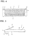
- the housing mounts a plurality of terminals, generally designated 3, which are spaced along the housing as best seen in Figures 2, 3 and 4.
- Housing 2 of connector 1 is a one-piece structure unitarily molded of dielectric material such as plastic or the like.
- the housing is thin or wafer-like and has a generally U-shaped configuration as seen best in Figures 2 and 4, as defined by a pair of spaced wing portions 4 joined by a cross portion 6.
- the housing defines a bottom surface 8 and a top surface 10 as best seen in Figures 1, 2, 4 and 5.
- wings 4 and cross portion 6 of housing 2 define an open area 12 (Figs. 2 and 4) into which the contact portions of terminals 3 project as will be described in greater detail hereinafter.
- the housing includes a pair of mounting posts 14 for insertion into appropriate mounting holes in one of the flat circuits, as seen in Figure 6.
- Each terminal 3 includes a base 16 (Fig. 1) anchored within cross portion 6 of housing 2, as by insert molding the base in the molded plastic housing.
- a tail 18 extends from base 16 rearwardly of the connector. The bottom surface of the tail is coplanar with bottom surface 8 of the housing. The tail is provided for connection to an appropriate conductor or circuit trace of the flat circuit on which the connector is mounted.
- a cantilevered beam, generally designated 20, extends forwardly of base 16 into open area 12 of the housing and terminates in a U-shaped joint 22.
- a contact arm 24 extends from the U-shaped joint back over cantilevered beam 20 and terminates in a contact portion 26 for engaging an appropriate conductor on a second flat circuit, as will be described hereinafter in relation to Figure 6.
- the cantilevered beam is narrowed, as at 27 (Fig. 4), inwardly of U-shaped joint 22.
- Contact portion 26 of each terminal is bifurcated, as seen best in Figures 2 and 3, to provide two points of contact for each terminal.
- the bottom-most point 28 (Fig. 1) of the U-shaped contact portion of the terminal is above bottom surface 8 of housing 2.
- cantilevered beam 20 of each terminal 3 includes a first bowed portion 30 projecting downwardly toward the first flat circuit on which the connector is mounted, as clearly seen in Figure 1, along with a second bowed portion 32 which projects upwardly toward the second flat circuit which engages contact portion 26 of contact arm 24 of the terminal. It can be seen in Figure 1 that each bowed portion 30 and 32 actually comprises straight lengths 30a and 32a, respectively, of cantilevered beam 20 meeting at apexes 30b and 32b, respectively.
- Figure 6 shows connector 1 mounted on a first flat circuit 34 which may be a printed circuit board, for instance. It can be seen that bottom surface 8 of housing 2 and the bottom surfaces of tails 18 of terminals 3 are coplanar and engage the top surface of flat circuit 34. Tails 18 typically are connected, as by soldering, to appropriate circuit traces or conductors on the top surface of flat circuit 34.
- Figure 6 also shows a second flat circuit 36 engaged with contact portion 26 of contact arm 24 of each terminal to bias the contact arm downwardly in the direction of arrow "A" about U-shaped joint 22.
- Second flat circuit 36 could be a second printed circuit board, a flat flexible cable or the like.
- contact arm 24 flexes in the direction of arrow "A" (Fig. 6) a significant amount versus the minimal flexing of cantilevered beam 20.
- This phenomenon is caused by the stiffening of the cantilevered beam by upwardly and downwardly bowed portions 30 and 32, respectively, of the cantilevered beam.
Landscapes
- Coupling Device And Connection With Printed Circuit (AREA)
- Multi-Conductor Connections (AREA)
Applications Claiming Priority (2)
| Application Number | Priority Date | Filing Date | Title |
|---|---|---|---|
| JP18141298 | 1998-06-12 | ||
| JP18141298A JP3903332B2 (ja) | 1998-06-12 | 1998-06-12 | 電気コネクタ |
Publications (2)
| Publication Number | Publication Date |
|---|---|
| EP0964478A2 true EP0964478A2 (fr) | 1999-12-15 |
| EP0964478A3 EP0964478A3 (fr) | 2000-07-12 |
Family
ID=16100321
Family Applications (1)
| Application Number | Title | Priority Date | Filing Date |
|---|---|---|---|
| EP99110386A Withdrawn EP0964478A3 (fr) | 1998-06-12 | 1999-05-28 | Connecteur électrique |
Country Status (3)
| Country | Link |
|---|---|
| US (1) | US6142790A (fr) |
| EP (1) | EP0964478A3 (fr) |
| JP (1) | JP3903332B2 (fr) |
Cited By (2)
| Publication number | Priority date | Publication date | Assignee | Title |
|---|---|---|---|---|
| DE20010669U1 (de) * | 2000-06-21 | 2001-10-31 | ITT Manufacturing Enterprises, Inc., Wilmington, Del. | Elektrische Verbindungseinrichtung |
| DE10030228A1 (de) * | 2000-06-20 | 2002-01-03 | Itt Mfg Enterprises Inc | Elektrische Verbindungsvorrichtung |
Families Citing this family (21)
| Publication number | Priority date | Publication date | Assignee | Title |
|---|---|---|---|---|
| JP4168507B2 (ja) * | 1999-01-29 | 2008-10-22 | モレックス インコーポレーテッド | 電気コネクタ |
| KR20010103792A (ko) * | 1999-03-08 | 2001-11-23 | 세이취크 제이 엘. | 기판 실장 커넥터 |
| US6855013B2 (en) * | 2000-05-08 | 2005-02-15 | Tyco Electronic Logistics Ag | LCD connector for printed circuit boards |
| US6604950B2 (en) * | 2001-04-26 | 2003-08-12 | Teledyne Technologies Incorporated | Low pitch, high density connector |
| US6730134B2 (en) | 2001-07-02 | 2004-05-04 | Intercon Systems, Inc. | Interposer assembly |
| US6488513B1 (en) | 2001-12-13 | 2002-12-03 | Intercon Systems, Inc. | Interposer assembly for soldered electrical connections |
| TWM291104U (en) * | 2005-11-04 | 2006-05-21 | Advanced Connectek Inc | Plate-to-plate connector |
| JP5500870B2 (ja) * | 2009-05-28 | 2014-05-21 | 新光電気工業株式会社 | 接続端子付き基板及び電子部品のソケット等 |
| US9022812B2 (en) * | 2011-11-02 | 2015-05-05 | Fci Americas Technology Llc | Electrical connector with reduced normal force |
| JP6073373B2 (ja) | 2012-02-07 | 2017-02-01 | スリーエム イノベイティブ プロパティズ カンパニー | ワイヤマウント電気コネクタ |
| US9553401B2 (en) | 2012-02-07 | 2017-01-24 | 3M Innovative Properties Company | Electrical connector for strain relief for an electrical cable |
| US9455503B2 (en) | 2012-02-07 | 2016-09-27 | 3M Innovative Properties Company | Electrical connector contact terminal |
| US9509094B2 (en) | 2012-02-07 | 2016-11-29 | 3M Innovative Properties Company | Board mount electrical connector with latch opening on bottom wall |
| EP2812951A4 (fr) | 2012-02-07 | 2015-10-28 | 3M Innovative Properties Co | Verrou de connecteur électrique |
| TWI496367B (zh) | 2012-10-09 | 2015-08-11 | Molex Inc | Card edge connector |
| CN105449422B (zh) * | 2014-08-28 | 2019-02-22 | 春源科技(深圳)有限公司 | 多件式fpc连接器 |
| US10263352B2 (en) * | 2016-06-10 | 2019-04-16 | Te Connectivity Corporation | Electrical contact pad for electrically contacting a connector |
| US10868377B2 (en) * | 2018-08-29 | 2020-12-15 | Avx Corporation | Electrical spring contact with integrated extending carrier portion |
| JP7195610B2 (ja) * | 2019-04-25 | 2022-12-26 | 北川工業株式会社 | 接触部材 |
| JP7450658B2 (ja) * | 2022-04-08 | 2024-03-15 | 日本航空電子工業株式会社 | コネクタおよびコネクタ・ケーブル |
| US20240421483A1 (en) * | 2023-06-15 | 2024-12-19 | Plume Design, Inc. | Spring member for antenna contact |
Family Cites Families (6)
| Publication number | Priority date | Publication date | Assignee | Title |
|---|---|---|---|---|
| US2509701A (en) * | 1948-03-12 | 1950-05-30 | Daven Company | Terminal panel |
| JPS6111284U (ja) * | 1984-06-26 | 1986-01-23 | 沖電線株式会社 | 基板接続コネクタ |
| JPH088550Y2 (ja) * | 1988-01-14 | 1996-03-06 | アンプ インコーポレーテッド | フラットケーブル用コネクタ |
| US5071371A (en) * | 1990-03-30 | 1991-12-10 | Molex Incorporated | Electrical card edge connector assembly |
| JPH069152B2 (ja) * | 1991-06-18 | 1994-02-02 | モレックス インコーポレーテッド | 水平基板接続用カードエッヂコネクタ及びその製法 |
| EP0735616A3 (fr) * | 1995-03-31 | 1997-03-19 | Wieland Elektrische Industrie | Connecteur électrique, notamment pour des plaquettes de circuits |
-
1998
- 1998-06-12 JP JP18141298A patent/JP3903332B2/ja not_active Expired - Fee Related
-
1999
- 1999-05-14 US US09/312,533 patent/US6142790A/en not_active Expired - Lifetime
- 1999-05-28 EP EP99110386A patent/EP0964478A3/fr not_active Withdrawn
Cited By (4)
| Publication number | Priority date | Publication date | Assignee | Title |
|---|---|---|---|---|
| DE10030228A1 (de) * | 2000-06-20 | 2002-01-03 | Itt Mfg Enterprises Inc | Elektrische Verbindungsvorrichtung |
| DE10030228C2 (de) * | 2000-06-20 | 2002-07-11 | Itt Mfg Enterprises Inc | Elektrischer Steckverbinder |
| DE20010669U1 (de) * | 2000-06-21 | 2001-10-31 | ITT Manufacturing Enterprises, Inc., Wilmington, Del. | Elektrische Verbindungseinrichtung |
| EP1168509A3 (fr) * | 2000-06-21 | 2002-04-03 | Itt Manufacturing Enterprises, Inc. | Dispositif de connexion électrique |
Also Published As
| Publication number | Publication date |
|---|---|
| JP2000012135A (ja) | 2000-01-14 |
| US6142790A (en) | 2000-11-07 |
| JP3903332B2 (ja) | 2007-04-11 |
| EP0964478A3 (fr) | 2000-07-12 |
Similar Documents
| Publication | Publication Date | Title |
|---|---|---|
| US6142790A (en) | Connector with flexible beam providing uniform contact pressure | |
| US5145384A (en) | Electrical connector and terminal therefor | |
| US5876222A (en) | Electrical connector for printed circuit boards | |
| US7695295B2 (en) | Flat circuit connector | |
| KR970000291Y1 (ko) | 표면 장착 전기 커넥터 어셈블리 | |
| US4621880A (en) | Electrical contact elements, connectors and assemblies | |
| US5993263A (en) | Reduced mating force electrical connector | |
| US5310360A (en) | Circuit board mounted modular phone jack | |
| EP0996196A3 (fr) | Connecteur ayant bornes avec extrémités de connexion à souder améliorées | |
| US5622519A (en) | Retention system for electrical connectors on printed circuit boards | |
| US5292265A (en) | Edge mounted circuit board electrical connector | |
| US8033861B2 (en) | Electrical connector with improved board lock having elastic portion abutting against optical drive disk | |
| US4645277A (en) | Connector for connecting boards | |
| US5893764A (en) | Board straddle mounted electrical connector | |
| CN110875538B (zh) | 用于电连接器的触头 | |
| CA2172216A1 (fr) | Connecteur electrique | |
| US4919626A (en) | Connector for IC card | |
| EP0942498A2 (fr) | Connecteur électrique avec un plot amélioré pour montage sur une plaque | |
| US6726499B1 (en) | Electrical connector having improved terminals | |
| US3947083A (en) | Edge contact | |
| KR100344047B1 (ko) | 단자 미부 정렬기를 구비한 인쇄 회로 기판 장착식 전기 커넥터 | |
| US6106308A (en) | Contact of an electrical connector having solder terminal capable of fitting with a housing of the connector | |
| EP0798809A2 (fr) | Mécanisme de verrouillage pour un connecteur pour un circuit imprimé flexible | |
| US6273748B1 (en) | Electrical connector assembly | |
| US7029319B2 (en) | Flat circuit connector |
Legal Events
| Date | Code | Title | Description |
|---|---|---|---|
| PUAI | Public reference made under article 153(3) epc to a published international application that has entered the european phase |
Free format text: ORIGINAL CODE: 0009012 |
|
| AK | Designated contracting states |
Kind code of ref document: A2 Designated state(s): DE FR GB IT |
|
| AX | Request for extension of the european patent |
Free format text: AL;LT;LV;MK;RO;SI |
|
| PUAL | Search report despatched |
Free format text: ORIGINAL CODE: 0009013 |
|
| AK | Designated contracting states |
Kind code of ref document: A3 Designated state(s): AT BE CH CY DE DK ES FI FR GB GR IE IT LI LU MC NL PT SE |
|
| AX | Request for extension of the european patent |
Free format text: AL;LT;LV;MK;RO;SI |
|
| RIC1 | Information provided on ipc code assigned before grant |
Free format text: 7H 01R 9/07 A, 7H 01R 23/72 B, 7H 01R 23/66 B |
|
| 17P | Request for examination filed |
Effective date: 20010108 |
|
| AKX | Designation fees paid |
Free format text: DE FR GB IT |
|
| STAA | Information on the status of an ep patent application or granted ep patent |
Free format text: STATUS: THE APPLICATION HAS BEEN WITHDRAWN |
|
| 18W | Application withdrawn |
Effective date: 20040724 |