EP0964530A1 - Funkübertragungsempfänger und Verfahren zur Interferenzunterdrückung - Google Patents
Funkübertragungsempfänger und Verfahren zur Interferenzunterdrückung Download PDFInfo
- Publication number
- EP0964530A1 EP0964530A1 EP98110369A EP98110369A EP0964530A1 EP 0964530 A1 EP0964530 A1 EP 0964530A1 EP 98110369 A EP98110369 A EP 98110369A EP 98110369 A EP98110369 A EP 98110369A EP 0964530 A1 EP0964530 A1 EP 0964530A1
- Authority
- EP
- European Patent Office
- Prior art keywords
- radio signals
- data
- radio
- wave front
- signals
- Prior art date
- Legal status (The legal status is an assumption and is not a legal conclusion. Google has not performed a legal analysis and makes no representation as to the accuracy of the status listed.)
- Withdrawn
Links
- 238000004891 communication Methods 0.000 title claims abstract description 34
- 238000000034 method Methods 0.000 title claims description 11
- 230000003044 adaptive effect Effects 0.000 claims abstract description 11
- 238000001228 spectrum Methods 0.000 claims abstract description 7
- 230000002452 interceptive effect Effects 0.000 description 17
- 230000000694 effects Effects 0.000 description 6
- 238000001514 detection method Methods 0.000 description 5
- 238000010586 diagram Methods 0.000 description 5
- 238000001914 filtration Methods 0.000 description 3
- 230000002123 temporal effect Effects 0.000 description 3
- 238000007476 Maximum Likelihood Methods 0.000 description 2
- 230000005540 biological transmission Effects 0.000 description 2
- 238000003491 array Methods 0.000 description 1
- 230000001413 cellular effect Effects 0.000 description 1
- 230000001427 coherent effect Effects 0.000 description 1
- 230000006835 compression Effects 0.000 description 1
- 238000007906 compression Methods 0.000 description 1
- 238000005516 engineering process Methods 0.000 description 1
- 238000005562 fading Methods 0.000 description 1
- 238000012986 modification Methods 0.000 description 1
- 230000004048 modification Effects 0.000 description 1
- 230000001172 regenerating effect Effects 0.000 description 1
Images

Classifications
-
- H—ELECTRICITY
- H04—ELECTRIC COMMUNICATION TECHNIQUE
- H04B—TRANSMISSION
- H04B1/00—Details of transmission systems, not covered by a single one of groups H04B3/00 - H04B13/00; Details of transmission systems not characterised by the medium used for transmission
- H04B1/69—Spread spectrum techniques
- H04B1/707—Spread spectrum techniques using direct sequence modulation
- H04B1/7097—Interference-related aspects
- H04B1/7103—Interference-related aspects the interference being multiple access interference
- H04B1/7107—Subtractive interference cancellation
-
- H—ELECTRICITY
- H04—ELECTRIC COMMUNICATION TECHNIQUE
- H04B—TRANSMISSION
- H04B1/00—Details of transmission systems, not covered by a single one of groups H04B3/00 - H04B13/00; Details of transmission systems not characterised by the medium used for transmission
- H04B1/69—Spread spectrum techniques
- H04B1/707—Spread spectrum techniques using direct sequence modulation
Definitions
- the present invention relates to radio communications receivers which operate to detect radio signals contemporaneously transmitted by first and second transmitters and to recover first and second data, which the radio signals represent. Furthermore the present invention relates to methods of recovering first and second data from contemporaneously transmitted first and second radio signals. In particular, but not exclusively the present invention relates to wireless communications systems which include receivers arranged to recover data contemporaneously transmitted from a plurality of different transmitters.
- Wireless communication systems are arranged to communicate data by transmitting radio signals representative of the data between transmitters and receivers of the system using part of the radio frequency spectrum.
- wireless communication systems are arranged to make an optimum use of an allocated part of the radio frequency spectrum.
- wireless communication systems are arranged to operate in accordance with a multiple access scheme which provides a means whereby a plurality of data communications channels may be contemporaneously supported in a way which, as far as possible, makes optimum use of the allocated radio frequency spectrum.
- An example of such a multiple acces scheme is time division multiple access in which data from a plurality of transmitters is communicated in a corresponding plurality of time slots into which a radio frequency carrier signal is divided. In this way a plurality of data communications channels are effected, with each time slot representing a contemporaneously supported channel.
- receivers arranged to operate within such systems are known to include adaptive antenna arrays which utilise adaptive beamforming techniques to the effect of exploiting spatial diversity, which is inherent in the communication of radio signals.
- a substantial increase in a number of communications channels provided by a wireless communications system may be effected by allowing transmission of radio signals contemporaneously.
- a data detector is assigned to each of the radio signals associated with a particular transmitter which have been separated in accordance with an angle of arrival of a wave front of the radio signals at the antenna array by the spatio-temporal filter, to the effect that the data detector recovers the data associated with a particular transmitter.
- wave front is used herein to refer to a component of a radio signal which arrives at an antenna array at a particular angle having reached the antenna array via one of a plurality of distinct propagation paths.
- wave front is used with analogue to the propagation of sound or compression waves, the front or leading part of which is known as the 'wave front'.
- a disadvantage with this known apparatus is that interfering wave fronts can only be cancelled completely by the spatial filter if a relative difference in an angle of arrival of the wave fronts is substantially small. Furthermore, if, for example, a wave front of interest experiences a deep fade as a result of fast fading caused by the radio communications channel, the wave fronts reconstructed by the spatio-temporal filter may be corrupted by a stronger interfering radio signal wave front generated by another transmitter to the effect that a data detector can not recover the data which the radio signals represent.
- the object of the invention is addressed generally by providing an antenna array and a spatio-temporal filter to separate the contemporaneously detected radio signal wave fronts and cancelling any interference between the signals before detecting the data which the radio signal wave fronts represent.
- radio communications receiver for detecting first and second contemporaneously transmitted radio signals representative of first and second data
- said receiver comprising an adaptive antenna means which operates to detect at least one wave front from said first radio signals, and at least one wave front from said second radio signals, a first data detector which operates to recover first data from said at least one first wave front, an interference cancellation means which operates to subtract said first radio signals, re-constituted from said first data, from said at least one second wave front, consequent upon interference from said at least one first wave front to said at least one second wave front, and a second data detector which operates to recover said second data from said at least one second wave front after the subtraction of said first wave front, whereby first and second data are communicated contemporaneously on at least common parts of the radio frequency spectrum.
- an adaptive antenna system By arranging for an adaptive antenna system to detect and separate radio signal wave fronts formed by different radio signals transmitted from different transmitters, and by subsequently effecting an interference cancellation of one wave front from one radio signal, from a wave front of another radio signal, data from a relatively weak wave front or one which is corrupted by a stronger interfering wave front may be detected by the receiver.
- the interference cancellation means may comprise a signal reconstitutor coupled to said first data detector, which operates to re-constitute said first radio signals in accordance with said detected first data and a form in which said first radio signals were transmitted, and a signal cancellation means which operates to substantially subtract said re-constituted first radio signals from said at least one second wave front thereby forming a substantially interference free version of said second radio signal.
- the interference cancellation means may further include a cross correlation estimator, coupled to said adaptive antenna means and which operates to determine a cross correlation factor representative of an amount by which said at least one second wave front is interfered by said at least one first radio signal wave front, and a scaling means coupled between said signal re-constitutor and said signal cancellation means and arranged to scaled said re-constituted signals with said correlation factor.
- a cross correlation estimator coupled to said adaptive antenna means and which operates to determine a cross correlation factor representative of an amount by which said at least one second wave front is interfered by said at least one first radio signal wave front
- a scaling means coupled between said signal re-constitutor and said signal cancellation means and arranged to scaled said re-constituted signals with said correlation factor.
- the receiver according to the present invention provides an advantage in that data from different contemporaneously transmitted radio signals may detected, without the complexity of performing a full joint detection process, or a full interference cancellation process.
- a joint detection process is that used for example in detecting and recovering data represented as time division-code division multiple access radio signals an explanation of which is provided in an article, entitled Performance of a Cellular Hybrid C-TDMA Mobile Radio System Applying Joint Detection and Coherent Receiver Antenna Diversity" by G. Blanz, A. Klein, M. Nadedhan and A. Steil published in the IEEE Journal on Selected Areas in Communications, Volume 12, no. 4, May 1994 at page 568, the content of which is incorporated herein by reference. Furthermore, by combining an adaptive antenna system, having a spatio-temporal filter, with interference cancellation, a flexible trade off between computational complexity and performance can be effected.
- a receiver in accordance with the present invention furthermore provides an advantage when used within a wireless mobile radio communications system in that a requirement for fast power control and soft hand over is substantially alleviated.
- the interference cancellation may be effected by regenerating the interfering signal from previously detected data from a stronger of the radio signal wavefronts, and subsequently cancelling this regenerated signal from the weaker of the signals before data detection.
- a receiver in accordance with the present invention may be used in either a mobile station or a base station of a wireless communication system.
- Interference cancellation may be effected reconstituting a stronger of the interfering signals by modulating and re-coding the detected data.
- the interference cancellation may be a joint detection processor in a case where the first and second radio signals have been generated in accordance with a time division-code division multiple access scheme.
- a method of recovering first and second data from contemporaneously transmitted first and second radio signals comprising the steps of detecting and separating the first and second radio signals into a plurality of radio signal wave fronts, at least one of which wave fronts is associated with the first radio signals, and at least one second of which wave fronts is associated with the second radio signals,
- the step of cancelling the first or the second radio signals from the other of the first or the second wave fronts comprises the steps of re-constituting the first or second radio signals consequent upon which of the first and second data is recovered, in accordance with the detected data and a form in which the radio signals were transmitted, and subtracting the re-constituted radio signals from the other of the first or the second radio signals.
- the method may further include the step of estimating a cross correlation factor between the first and the second radio signals, and scaling the re-constituted signals with the cross-correlation factor before subtracting the signals from the other of the first and second radio signals.
- FIG. 1 An example embodiment of the present invention will be described with reference to a wireless communications system, and in particular to a mobile radio telephone communications system.
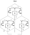
- An example block diagram of a mobile radio communication system is shown in Figure 1.
- three base stations BS form part of a mobile radio network, interconnected via an infra-structure (not shown).
- Data is communicated between mobile stations MS and the base stations BS, by transmitting and receiving radio signals 1, between the base stations BS and the mobile stations MS operating within a radio coverage area effected by each of the base stations which forms coverage cells 3, 3', 3''.
- the radio coverage area is shown illustrated as a broken line 2, and serves to indicate a boundary within which radio communications can be effected with the mobile stations MS.
- the mobile stations MS communicate with the base stations BS via radio signals generated in accordance with that determined by the standard the Global System for Mobiles (GSM).
- GSM Global System for Mobiles
- two mobile stations MS1, and MS2, in cell 3 are arranged to communicate bursts of radio signals contemporaneously in the same time slot and on the same frequency.
- a receiver embodied within the base station BS is arranged to detect and separate the first and the second radio signals transmitted by the first and the second mobile stations MS1, MS2, in accordance with an inherent spatial diversity of these radio signals.
- An example embodiment of this receiver is shown in Figure 2, where parts also appearing in Figure 1 bear identical designations.
- an array of antennas 4 is provided with each antenna 6 of the array 4, being coupled to a corresponding input of a spatio-temporal filter 8. Coupled to further inputs of the spatio-temporal filter 8, is a direction of arrival estimator 10.
- the direction of arrival estimator 10 operates to generate a plurality of scaling coefficients a i which are fed to first inputs of a plurality of multipliers 12, which form a spatial filter, 13. In effect each version of the radio signals detected by each of the antennas 6 are scaled with a corresponding coefficient a i generated by the directional arrival estimator 10.
- the scaled versions of the radio signal are then fed to a wave front detector means 11, which operates to combine the received scaled radio signals to form at the outputs thereof each of a plurality of radio signal wavefronts represented by y 1 .
- Each of the radio signal wavefronts is associated with radio signals transmitted by one of the mobiles and arriving at the antenna array 4 at a particular angle of arrival.
- the spatio temporal filter 8 operates to separate as far as possible, radio signals contemporaneously transmitted by each of the mobiles in accordance with the angle of arrival of these radio signals at the antenna array.
- a plurality of wavefronts may arrive at the antenna array which have been generated by the same transmitter.
- the wavefronts y 1 and y 2 are associated with the radio signals transmitted by the first mobile station MS1, and are therefore fed to the same data detector.
- the wave front detector means 11 operates to estimate the channel impulse response associated with each of the wavefronts and thereby determines a relative strength of each of the wavefronts.
- the channel impulse responses are estimated by correlating the radio signals corresponding to each wave front with a training sequence embodied within the radio signals and which is known at the receiver.
- the spatio-temporal filter 8 is able to determine whether data may be recovered from a particular set of wavefronts associated with the same transmitted radio signals.
- the wavefronts y 1 and y 2 associated with MS1 are fed to a data detector 14, which operates to detect and recover the data represented by these wavefronts y 1 and y 2 .
- the data is modulated onto the radio frequency signals in accordance with a radio communications transmission process determined in accordance with the GSM system.
- the data detector comprises a viterbi equaliser 16 and a data decoder 18.
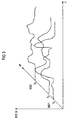
- FIG. 3 An example of the channel impulse response estimates determined by the wave front detector means 11, is illustrated in Figure 3.
- the signal strength of the radio signals generating the wavefronts y 1 and y 2 is considerably greater than the signal strength of the radio signals generating the wave front y 3 transmitted by the second mobile station MS2. Therefore, in order to detect and recover the data communicated by the wavefront y 3 , the stronger interfering radio signal wave fronts y 1 and y 2 generated by MS1, must be cancelled from the radio signal wave front y 3 before data is detected by the data detector 20. In this way, the data represented by the radio signals transmitted by mobile station 2 may be recovered from the contemporaneously transmitted and thereby mutually interfering radio signals detected by the antenna array.
- a signal cancellation means 22 is provided which is comprised of a signal re-constitutor 24 and a cross correlation estimator 26 and a signal cancellation means 28.
- the temporal filter combiner operates to generate the channel impulse response corresponding to each of the mutually interfering radio signals from MS1 and MS2, by comparing the detected combined radio signal wavefronts with a training sequence embodied in the transmitted radio signals which is known to the temporal filter and combiner. Furthermore, by comparing the detected training sequences from each of the radio signals transmitted by MS1 and MS2, an estimate of a cross correlation factor, between the radio signal wavefronts may be determined. This is estimated by the cross correlation detector 26 and provides a scaling factor to scale the reconstituted interfering signal from MS1.
- the signal re-constitutor 24 operates to remodulate and recode the data which is detected at the output of the data detector 14.
- the signal re-constitutor 24 there is a representation of the radio signals as transmitted by the mobile station MS1.
- the correlation factor generated by the cross correlation detector 26 a representation of the interfering signals y 1 and y 2 as detected at the antenna array, is generated at the output of the cross correlation detector. This is effected by the cross correlation factor ⁇ , which is fed to the multiplier 27, which operates to scale the re-constituted signals with the cross correlation factor ⁇ .
- the radio signals corresponding to the detected wavefront y 3 are therefore fed on a first input to the signal cancellor 28.
- the signal cancellor subtracts the interfering signals from mobile station MS1 from those signals from mobile station MS2 represented by the detected wavefront y 3 .
- At the output of the signal cancellor 28 radio signals substantially corresponding to those received only from mobile station 2 are provided which are fed to data detected data 20 which operates to recover data transmitted by the second mobile station MS2.
- W-CDMA wideband code division multiple access
- TD-CDMA time division-code division multiple access signals
- TDMA time division multiple access
Landscapes
- Engineering & Computer Science (AREA)
- Computer Networks & Wireless Communication (AREA)
- Signal Processing (AREA)
- Noise Elimination (AREA)
Priority Applications (3)
| Application Number | Priority Date | Filing Date | Title |
|---|---|---|---|
| EP98110369A EP0964530A1 (de) | 1998-06-05 | 1998-06-05 | Funkübertragungsempfänger und Verfahren zur Interferenzunterdrückung |
| US09/325,867 US6301470B1 (en) | 1998-06-05 | 1999-06-04 | Radio communications receiver and method of recovering data from radio signals |
| CN99108312.1A CN1221087C (zh) | 1998-06-05 | 1999-06-07 | 从无线电信号恢复数据的无线电通信接收机和方法 |
Applications Claiming Priority (1)
| Application Number | Priority Date | Filing Date | Title |
|---|---|---|---|
| EP98110369A EP0964530A1 (de) | 1998-06-05 | 1998-06-05 | Funkübertragungsempfänger und Verfahren zur Interferenzunterdrückung |
Publications (1)
| Publication Number | Publication Date |
|---|---|
| EP0964530A1 true EP0964530A1 (de) | 1999-12-15 |
Family
ID=8232078
Family Applications (1)
| Application Number | Title | Priority Date | Filing Date |
|---|---|---|---|
| EP98110369A Withdrawn EP0964530A1 (de) | 1998-06-05 | 1998-06-05 | Funkübertragungsempfänger und Verfahren zur Interferenzunterdrückung |
Country Status (3)
| Country | Link |
|---|---|
| US (1) | US6301470B1 (de) |
| EP (1) | EP0964530A1 (de) |
| CN (1) | CN1221087C (de) |
Cited By (3)
| Publication number | Priority date | Publication date | Assignee | Title |
|---|---|---|---|---|
| WO2001099301A1 (fr) * | 2000-06-22 | 2001-12-27 | Nortel Networks Limited | Procede et dispositif d'annulation de l'interference dans un recepteur |
| US7688774B2 (en) | 2002-01-28 | 2010-03-30 | Nokia Corporation | Interference cancellation in radio system receiver |
| EP1537650A4 (de) * | 2002-07-19 | 2010-06-09 | Interdigital Tech Corp | Gruppenweise sukzessive steuerungslöschung für die bolckübertragung mit empfangsunterscheidung |
Families Citing this family (11)
| Publication number | Priority date | Publication date | Assignee | Title |
|---|---|---|---|---|
| JP4087023B2 (ja) * | 1998-09-22 | 2008-05-14 | シャープ株式会社 | ミリ波帯信号送受信システムおよびミリ波帯信号送受信システムを具備した家屋 |
| CN1118200C (zh) * | 1999-08-10 | 2003-08-13 | 信息产业部电信科学技术研究院 | 基于智能天线和干扰抵销的基带处理方法 |
| KR100596413B1 (ko) * | 2001-10-24 | 2006-07-03 | 삼성전자주식회사 | 송/수신 다중 안테나를 포함하는 이동 통신 장치 및 방법 |
| WO2003041283A2 (en) * | 2001-11-07 | 2003-05-15 | Efficient Spectrum, Inc. | Digital adaptive beamforming and demodulation apparatus and method |
| US7363011B2 (en) * | 2002-11-05 | 2008-04-22 | Nokia Corporation | Method and apparatus for estimating the impulse response of a radio channel based on a calculated correlation sequence |
| WO2004066539A2 (en) * | 2003-01-15 | 2004-08-05 | Symbol Technologies, Inc. | Light fixture wireless access points |
| GB0327041D0 (en) * | 2003-11-21 | 2003-12-24 | Roke Manor Research | Apparatus and methods |
| US7724832B2 (en) * | 2004-05-27 | 2010-05-25 | Texas Instruments Incorporated | MIMO decoding |
| CA2516525A1 (en) * | 2005-08-15 | 2007-02-15 | Research In Motion Limited | Interference canceling matched filter (icmf) |
| US8938038B2 (en) * | 2012-02-02 | 2015-01-20 | Telefonaktiebolaget L M Ericsson (Publ) | Extending the set of addressable interferers for interference mitigation |
| EP3171527B1 (de) * | 2014-07-15 | 2019-06-19 | LG Electronics Inc. | Verfahren, mit dem ein mimo-empfänger ein empfangssignal durch ausrichtung einer vielzahl von schichten durch re-gruppeneinheiten verarbeitet |
Citations (3)
| Publication number | Priority date | Publication date | Assignee | Title |
|---|---|---|---|---|
| EP0526439A1 (de) * | 1991-08-02 | 1993-02-03 | Ericsson Inc. | Subtraktive Kodedivisionsdemodulationsschaltung |
| WO1997002666A1 (en) * | 1995-06-30 | 1997-01-23 | Nokia Telecommunications Oy | Reception method and base station receiver |
| WO1997008846A1 (en) * | 1995-08-28 | 1997-03-06 | Qualcomm Incorporated | Method and system for subtractive multiple access interference cancellation |
Family Cites Families (2)
| Publication number | Priority date | Publication date | Assignee | Title |
|---|---|---|---|---|
| JP3526196B2 (ja) * | 1997-01-07 | 2004-05-10 | 株式会社東芝 | アダプティブアンテナ |
| US6157847A (en) * | 1999-06-29 | 2000-12-05 | Lucent Technologies Inc. | Base station system including parallel interference cancellation processor |
-
1998
- 1998-06-05 EP EP98110369A patent/EP0964530A1/de not_active Withdrawn
-
1999
- 1999-06-04 US US09/325,867 patent/US6301470B1/en not_active Expired - Fee Related
- 1999-06-07 CN CN99108312.1A patent/CN1221087C/zh not_active Expired - Fee Related
Patent Citations (3)
| Publication number | Priority date | Publication date | Assignee | Title |
|---|---|---|---|---|
| EP0526439A1 (de) * | 1991-08-02 | 1993-02-03 | Ericsson Inc. | Subtraktive Kodedivisionsdemodulationsschaltung |
| WO1997002666A1 (en) * | 1995-06-30 | 1997-01-23 | Nokia Telecommunications Oy | Reception method and base station receiver |
| WO1997008846A1 (en) * | 1995-08-28 | 1997-03-06 | Qualcomm Incorporated | Method and system for subtractive multiple access interference cancellation |
Cited By (7)
| Publication number | Priority date | Publication date | Assignee | Title |
|---|---|---|---|---|
| WO2001099301A1 (fr) * | 2000-06-22 | 2001-12-27 | Nortel Networks Limited | Procede et dispositif d'annulation de l'interference dans un recepteur |
| FR2810820A1 (fr) * | 2000-06-22 | 2001-12-28 | Nortel Matra Cellular | Procede et dispositif de reception d'un signal radio |
| US7167529B2 (en) | 2000-06-22 | 2007-01-23 | Nortel Networks Limited | Method and device for radio signal reception |
| US7688774B2 (en) | 2002-01-28 | 2010-03-30 | Nokia Corporation | Interference cancellation in radio system receiver |
| EP1537650A4 (de) * | 2002-07-19 | 2010-06-09 | Interdigital Tech Corp | Gruppenweise sukzessive steuerungslöschung für die bolckübertragung mit empfangsunterscheidung |
| US8284854B2 (en) | 2002-07-19 | 2012-10-09 | Interdigital Technology Corporation | Groupwise successive interference cancellation for block transmission with reception diversity |
| US8553820B2 (en) | 2002-07-19 | 2013-10-08 | Interdigital Technology Corporation | Groupwise successive interference cancellation for block transmission with reception diversity |
Also Published As
| Publication number | Publication date |
|---|---|
| US6301470B1 (en) | 2001-10-09 |
| CN1238611A (zh) | 1999-12-15 |
| CN1221087C (zh) | 2005-09-28 |
Similar Documents
| Publication | Publication Date | Title |
|---|---|---|
| AU709418B2 (en) | Reception method and base station receiver | |
| JP4343694B2 (ja) | 送信チャネル間のゲインオフセットを決定する方法 | |
| US5901185A (en) | Systems and methods for data-augmented, pilot-symbol-assisted radiotelephone communications | |
| US7656936B2 (en) | Method and system for interference reduction in a wireless communication network using a joint detector | |
| KR100663525B1 (ko) | 공간-시간 빔 형성을 위한 간섭전력 측정 장치 및 방법 | |
| US6301470B1 (en) | Radio communications receiver and method of recovering data from radio signals | |
| US7463672B2 (en) | Technique for adaptive multiuser equalization in code division multiple access systems | |
| EP1802000B1 (de) | Vorrichtung und Verfahren zur Unterdrückung von Nachbarzell-Störsignalen in einem Breitbandkommunikationssystem | |
| US20060126753A1 (en) | Apparatus and method for detecting space-time multi-user signal of base station having array antenna | |
| CN101814931A (zh) | Td-scdma系统中多普勒频移估计和补偿的方法 | |
| KR20000016966A (ko) | 무선신호에서데이터를복구하는수신기및방법 | |
| US20120208567A1 (en) | High-performance cellular telephone receiver | |
| US6324160B1 (en) | Adaptive receiver for CDMA base stations | |
| US6718162B1 (en) | Receiver for a CDMA mobile radiocommunication system | |
| EP0674401B1 (de) | Spreizspektrumsignalempfänger | |
| US7486750B1 (en) | Method for obtaining information regarding interference in the receiver of a message transmission system | |
| EP1198150B1 (de) | Verfahren zur Abschätzung eines Abwärtskanals | |
| JP2003500973A (ja) | 移動式無線電話アプリケーションのための受信方法および受信装置 | |
| JP2001016148A (ja) | アレーアンテナを用いた干渉キャンセラ装置、干渉レプリカ生成ユニット | |
| WO2005002067A2 (en) | Multi-carrier spread spectrum using non-linear modification of sub-carrier bands | |
| JP3779554B2 (ja) | 周波数オフセット推定方法及び周波数オフセット推定器 | |
| US6947473B1 (en) | Receiver and method of recovering data from radio signals | |
| GB2336506A (en) | Method of Reducing Co-channel Interference | |
| JP3537203B2 (ja) | アンテナダイバーシチ受信機 | |
| Pelletier et al. | Group optimal space-time MUD with beamforming |
Legal Events
| Date | Code | Title | Description |
|---|---|---|---|
| PUAI | Public reference made under article 153(3) epc to a published international application that has entered the european phase |
Free format text: ORIGINAL CODE: 0009012 |
|
| AK | Designated contracting states |
Kind code of ref document: A1 Designated state(s): DE ES FR GB IT |
|
| AX | Request for extension of the european patent |
Free format text: AL;LT;LV;MK;RO;SI |
|
| 17P | Request for examination filed |
Effective date: 20000121 |
|
| AKX | Designation fees paid |
Free format text: DE ES FR GB IT |
|
| RAP1 | Party data changed (applicant data changed or rights of an application transferred) |
Owner name: NOKIA SIEMENS NETWORKS GMBH & CO. KG |
|
| RAP3 | Party data changed (applicant data changed or rights of an application transferred) |
Owner name: NOKIA SIEMENS NETWORKS S.P.A. |
|
| RAP3 | Party data changed (applicant data changed or rights of an application transferred) |
Owner name: NOKIA SIEMENS NETWORKS GMBH & CO. KG |
|
| 17Q | First examination report despatched |
Effective date: 20071115 |
|
| STAA | Information on the status of an ep patent application or granted ep patent |
Free format text: STATUS: THE APPLICATION IS DEEMED TO BE WITHDRAWN |
|
| 18D | Application deemed to be withdrawn |
Effective date: 20081231 |