EP0964531A1 - Zellselektion in einer mobilen Satelliten Anordnung mit Teilnehmer Ortsbestimmung durch Messung der Signallaufzeit und Dopplerverschiebung - Google Patents
Zellselektion in einer mobilen Satelliten Anordnung mit Teilnehmer Ortsbestimmung durch Messung der Signallaufzeit und Dopplerverschiebung Download PDFInfo
- Publication number
- EP0964531A1 EP0964531A1 EP98304655A EP98304655A EP0964531A1 EP 0964531 A1 EP0964531 A1 EP 0964531A1 EP 98304655 A EP98304655 A EP 98304655A EP 98304655 A EP98304655 A EP 98304655A EP 0964531 A1 EP0964531 A1 EP 0964531A1
- Authority
- EP
- European Patent Office
- Prior art keywords
- cell
- user terminal
- satellite
- radio resources
- predetermined
- Prior art date
- Legal status (The legal status is an assumption and is not a legal conclusion. Google has not performed a legal analysis and makes no representation as to the accuracy of the status listed.)
- Withdrawn
Links
- 230000001413 cellular effect Effects 0.000 claims abstract description 21
- 238000000034 method Methods 0.000 claims description 34
- 238000004891 communication Methods 0.000 claims description 13
- 230000000694 effects Effects 0.000 claims description 2
- 230000001419 dependent effect Effects 0.000 claims 2
- 229920000468 styrene butadiene styrene block copolymer Polymers 0.000 description 38
- 230000001934 delay Effects 0.000 description 5
- 238000012937 correction Methods 0.000 description 4
- 230000006870 function Effects 0.000 description 4
- 238000007726 management method Methods 0.000 description 4
- 238000010586 diagram Methods 0.000 description 3
- 238000005259 measurement Methods 0.000 description 3
- 230000004044 response Effects 0.000 description 3
- 238000001228 spectrum Methods 0.000 description 3
- 229920000638 styrene acrylonitrile Polymers 0.000 description 3
- 238000004458 analytical method Methods 0.000 description 2
- 230000005540 biological transmission Effects 0.000 description 2
- 238000013461 design Methods 0.000 description 2
- 230000000977 initiatory effect Effects 0.000 description 2
- 238000013459 approach Methods 0.000 description 1
- 230000000295 complement effect Effects 0.000 description 1
- 238000007796 conventional method Methods 0.000 description 1
- 230000003111 delayed effect Effects 0.000 description 1
- 238000002296 dynamic light scattering Methods 0.000 description 1
- 238000005516 engineering process Methods 0.000 description 1
- 230000002045 lasting effect Effects 0.000 description 1
- 238000013507 mapping Methods 0.000 description 1
- 238000010295 mobile communication Methods 0.000 description 1
- 230000001151 other effect Effects 0.000 description 1
- 229920003258 poly(methylsilmethylene) Polymers 0.000 description 1
- 238000013061 process characterization study Methods 0.000 description 1
- 230000000717 retained effect Effects 0.000 description 1
- 238000000926 separation method Methods 0.000 description 1
- 230000001360 synchronised effect Effects 0.000 description 1
- 239000002699 waste material Substances 0.000 description 1
Images



Classifications
-
- H—ELECTRICITY
- H04—ELECTRIC COMMUNICATION TECHNIQUE
- H04B—TRANSMISSION
- H04B7/00—Radio transmission systems, i.e. using radiation field
- H04B7/14—Relay systems
- H04B7/15—Active relay systems
- H04B7/185—Space-based or airborne stations; Stations for satellite systems
- H04B7/1853—Satellite systems for providing telephony service to a mobile station, i.e. mobile satellite service
- H04B7/18545—Arrangements for managing station mobility, i.e. for station registration or localisation
- H04B7/18547—Arrangements for managing station mobility, i.e. for station registration or localisation for geolocalisation of a station
- H04B7/1855—Arrangements for managing station mobility, i.e. for station registration or localisation for geolocalisation of a station using a telephonic control signal, e.g. propagation delay variation, Doppler frequency variation, power variation, beam identification
Definitions
- the present invention relates to a method of controlling the allocation of radio resources to a mobile user terminal in a cellular satellite mobile telephone system.
- IRIDIUMTM satellite cellular system and described in, for example, EP-A-0 365 885 and US Patent No. 5 394 561 (Motorola), makes use of a constellation of so-called low earth orbit (LEO) satellites, that have an orbital radius of 780 km.
- LEO low earth orbit
- Mobile user terminals such as telephone handsets establish a link to an overhead orbiting satellite, from which a call can be directed to another satellite in the constellation and then typically to a ground station which is connected to conventional land-based networks.
- a signal from a mobile user terminal such as a mobile handset is directed firstly to the satellite and then to a ground station or satellite access node (SAN), which is connected to a conventional land-based telephone network.
- SAN satellite access node
- GSM digital terrestrial cellular technology
- simpler satellite communication techniques can be used than with a LEO network.
- a cellular mobile communication system which allows random access by mobile user terminals needs to include a specification of how a terminal should select a particular cell for access.
- the choice of cell is important since time, frequency and interference constraints may mean that support of a dedicated radio resource is not possible if the terminal has not selected the most appropriate cell.
- Conventional cell selection techniques use power measurements to determine the optimum cell for access. Typically, this involves selecting the best cell by using a ranking of received signal strengths on a beacon frequency of each cell, possibly offset using broadcast information related to the power transmitted from the base station. In terrestrial cellular systems, a 35 kilometre radius around a base station can typically be accommodated. Terminals which are outside this area cannot be supported.
- the above problems contribute to the fact that a mobile user terminal using received signal strength to determine the optimum cell for access in a satellite cellular system will frequently select a cell through which communications are not supportable.
- the present invention aims to improve the cell selection process.
- a method of controlling the allocation of radio resources to a mobile user terminal in a cellular satellite mobile telephone system comprising determining whether the difference between a position of the user terminal on the Earth's surface and a predetermined position associated with a given cell falls within predetermined limits, and controlling the allocation of radio resources to the user terminal in dependence thereon.
- the allocation of radio resources may be controlled by deciding whether to allocate or deny radio resources associated with the given cell to the user terminal.
- the predetermined position may be defined by reference to a characteristic associated with a signal from the satellite providing the cell, such as a path delay or a frequency shift or other effect experienced by the signal as a result of the position or velocity of the satellite.
- the characteristic may be a path delay for a signal from the satellite providing the cell to a point on the Earth's surface within the cell.
- a plurality of such positions for which the signal has a constant path delay to the satellite may together define a Z-arc.
- the characteristic may be a Doppler shift in the frequency of a signal from the satellite providing the cell to a point on the Earth's surface within the cell.
- a plurality of such positions for which the signal frequency has a constant Doppler shift may together define a frequency Z-arc.
- a method of allocating radio resources to a mobile user terminal in a satellite mobile telephone system including a satellite providing a plurality of cells having radio resources available to provide communications coverage over a region of the Earth's surface, comprising determining whether the user terminal lies within the limits of a given cell, wherein said limits are predefined by reference to a predetermined position within the cell.
- the present invention also provides a method of cell selection for a mobile user terminal in a cellular satellite mobile telephone system, comprising: selecting a cell for use by the user terminal in dependence on a comparison of a position of the user terminal in relation to a predetermined position within a given cell.
- a satellite mobile telephone system comprising a plurality of satellites, each providing a plurality of cells having radio resources available to provide communications coverage via a user terminal over a region of the Earth's surface, the system comprising: means for determining whether the difference in the position of the user terminal on the Earth's surface and a predetermined position within a given cell lies within predetermined limits; and means responsive to said determination to control the allocation of radio resources to the user terminal.
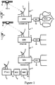
- a satellite mobile telephone system comprises a plurality of satellite access nodes (SAN) 1a, 1b, 1c interconnected by a high capacity digital network 2 ("the backbone network"), a plurality of satellites 3a, 3b, a plurality of user terminals (UT) 4a, 4b, gateways (GW) 5a, 5b, 5c providing connections between the SANs 1a, 1b, 1c and other networks 6, a network management centre (NMC) 7, a satellite control centre (SCC) 8 and a tracking, telemetry and control station (TT&C) 9.
- the NMC 7, the SCC 8 and the TT&C 9 are interconnected by a lower capacity digital network 10 which is also connected to the backbone network 2.
- the other networks 6 comprise the public switched telephone network (PSTN), terrestrial cellular telephone networks and the like.
- the SCC 8 and the TT&C 9 control the operation of the satellites 3a, 3b, for instance setting transmit power levels and transponder input tuning, as directed by the NMC 7. Telemetry signals from the satellites 3a, 3b are received by the TT&C 9 and processed by the SCC 8 to ensure that the satellites 3a, 3b are functioning correctly.
- a UT 4a, 4b communicates with SAN 1a, 1b via the satellites 3a, 3b using a TDMA scheme over a link comprising a downlink channel and an uplink channel.
- the channels comprise TDMA time slots on frequencies allocated on initiation of the call or re-allocated during a call.
- the satellite network is designed to provide worldwide coverage, so the satellites 3a, 3b form part of a constellation of satellites, which may be arranged in several orbits.
- two orbits of five satellites are used, which can be shown to provide coverage of a major pan of the surface of the earth, in which for a 10° satellite elevation angle, one satellite can be accessed by a UT all of the time and two satellites can be accessed for at least 80% of the time, thereby providing system diversity.
- Further satellites may be included in the constellation in order to provide additional redundancy and diversity.
- the satellites are typically arranged in a medium earth orbit (MEO) constellation, for example with an orbital radius of 10,355 km, although the invention is not restricted to a particular orbital radius.
- MEO medium earth orbit
- satellites 3a, 3b are shown in a common orbit and are tracked by the antenna arrangement 11 of each SAN 1a, 1b, 1c.
- each SAN includes four antennas for tracking individual satellites of the constellation, with one spare antenna.
- the SANs are spaced around the earth in order to provide continuous coverage.
- SAN 1a may be located in Europe whereas SAN 1b may be located in Africa, SAN 1c in America and other SANs may be located elsewhere.
- the SAN 1b is shown communicating with UT 4b via satellite 3b.
- GB-A-2 295 296 For further details of the satellite network, reference is directed to GB-A-2 295 296.
- the satellites 3a, 3b are in non-geostationary orbits and comprise generally conventional satellites, such as the known Hughes HS601 model, which have a plurality of satellite transponders including forward and return link communications transponders 12a, 12b, and which may further include features as disclosed in GB-A-2 288 913.
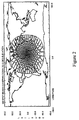
- Each satellite 3a, 3b is arranged to generate an array of beams, one for each cell, covering a footprint beneath the satellite, each beam including a number of different frequency channels and time slots.
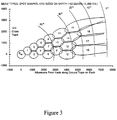
- each satellite 3a, 3b produces a fixed pattern of 163 spot beams, with the shapes of the spot beams varying as a result of the curvature of the earth to produce 19 different beam types (0 - 18), as shown in Figure 3.
- a UT 4a, 4b is shown in more detail in Figure 4 and is generally similar to the units presently available for GSM networks. It comprises a codec (not shown), a controller 13, a microphone 14, a loudspeaker 15, a battery 16, a keypad 17, a radio frequency interface (not shown), an antenna 18, a display 19 and a subscriber identification module (SIM) smart card (not shown).
- the codec comprises a low bit-rate coder, which generates a speech bit stream at 3.6 kbits/s, together with a channel coder, which applies error correction codes to the speech bit stream to produce an encoded bit stream at 4.8 kbits/s.
- the low bit-rate coder is a linear predictive coder.
- the channel coder uses Viterbi coding.
- the codec also comprises complementary decoders.
- the controller 13 comprises a microprocessor and RAM and ROM memory.
- the microprocessor operates in accordance with a control program stored in the ROM memory.
- the controller can exchange control and telemetry data with a SAN 1a, b, c using the radio frequency interface.
- the SIM includes a processor and a non-volatile memory which stores data identifying the subscriber and data for use in encrypted communication, as well as information relating to system operation, for example, a set of system reference frequencies.
- Each SAN 1a, 1b, 1c consists of a satellite base station SBS 20 which is coupled to the plurality of dish antennas 11 for tracking the satellites 3a, 3b.
- the SBS 20 comprises an SBS Controller 21 which controls the antennas 11 and which is coupled to a Local Satellite Resource Management Centre (Local SRMC) 22.
- the SBS 20 is also coupled to a Payload Control System (PCS) 23.
- PCS Payload Control System
- a PCS 23 exists in half of the SBSs in a system.
- a mobile satellite switching centre MSSC 24 is coupled to the SBS 20 and to a satellite visitor location register VLR SAT 25, which maintains a record of the individual UTs 4a, 4b which are making use of the particular SBS 20.
- the MSSC 24 provides similar functionality to terrestrial cellular mobile switching centres in managing and controlling the routing of calls between the UT 4a, 4b and the terrestrial networks 6.
- the NMC 7 includes a Satellite Resource Management Centre (SRMC) 26, which is connected to each SBS Controller 21 via a connection 27 from the backbone network 2.
- SRMC Satellite Resource Management Centre
- SRMS Satellite Resource Management System
- the SRMC 26 centrally plans, in non-real time, how the frequency, TDMA time slot and satellite power resources should be managed for optimum efficiency, based on the predicted traffic demands of the various SBSs. It analyses historical traffic data together with satellite ephemeris data, available frequencies and so on, to generate frequency plans to enable the overall satellite constellation to meet expected traffic requirements, as well as generating satellite transponder configuration plans to match the frequency plans. The SRMC 26 further determines how time slots on the planned frequencies are to be shared between the Local SRMCs 22 at each SBS. The resulting plans are known as Burst Time Frequency Plans (BTFPs) and contain pools of available TDMA time slots and frequencies.
- BTFPs Burst Time Frequency Plans
- the BTFPs are communicated to each Local SRMC 22 at each SBS 20 in non-real time. Real-time time slot allocations are then made by the Local SRMC 22 at each SBS 20 from its local pool, for use by each satellite spot beam, in response to requests from the SBS Controller 21.
- the transponder configuration plans for each satellite are communicated to one nominated PCS 23 at an SBS 20 in the coverage of each satellite, from where they are uploaded to the relevant satellites.
- the various functions of the SRMS system occur at very different timescales; some functions, such as the on-demand allocation of time slots, occur in real-time, in response to requests from each SBS. Other functions are best performed typically once a day, for example, the global frequency planning or the control of the satellite transponder configurations, as they require extensive information exchange between distant elements of the system.
- a UT 4a, 4b which requests the opening of a traffic channel, which is used to carry most types of voice and data traffic, is allocated appropriate radio resources by the relevant SBS 20 from its local resource pool.
- These resources include a specified beam on the satellite, frequency and TDMA time slot allocations, an appropriate power level for the service, together with a parameter known as a Z-arc.
- These resources are managed as appropriate, with, for example, provision for handover procedures to maintain the communications link when movement by the user and/or the satellites requires a different time slot, frequency, beam, Z-arc, satellite or ground station to maintain the link.
- the requirement for the Z-arc parameter results from the TDMA frame structure, and is explained in detail below.
- a traffic channel is made up of a plurality of TDMA frames, each frame comprising six time slots and lasting for 40 ms. Each time slot lasts 6.67 ms.
- the return path time slots r0, ..., r5 are shifted relative to the forward path time slots f0, ..., f5. The degree by which they are shifted varies in relation to the distance from the satellite nadir and the cell to which a beam is directed because of the different propagation times.
- the signal In a terrestrial cellular mobile telephone network, the signal typically takes a few microseconds to travel from a base transmitter site antenna to a mobile station and any variations are generally insignificant. Consequently, the TDMA time slot pattern is retained at the mobile station.
- the time taken for signals to travel between a satellite 3a, 3b and a UT 4a, 4b is longer than a time slot.
- the one way propagation time to the nadir is approximately 34.5 ms, which is comparable with the frame duration. This situation is further complicated by there being a significant difference between the path length to the cell at the satellite's nadir and the path lengths to the cells at the edge of the satellite's footprint.
- the one way propagation time to a UT which sees the satellite at 0° elevation is approximately 51.6 ms. This leads to significant differences in the times at which bursts arrive at UTs and in the times when UTs are required to transmit in order for their signals to fit in with the TDMA frame structure at the satellite.
- a transmission burst (Tx) 30 for TDMA slot 0 at the satellite is received as Rx burst 31 by a UT 4a at a time t PD1 later, where t PD1 is the one-way path delay from the satellite antenna to the UT antenna.
- a corresponding Tx burst 32 at the UT 4a is also received at the satellite at a time t PD1 later. If the UT 4a moves further from the satellite nadir, then the path delay t PD2 is greater than t PD1 , so that the Rx burst 33 will be received correspondingly later relative to Rx burst 31.
- the necessary synchronisation is achieved by referencing the burst timing to one of a number of specific path delay values in each spot beam at which there is zero offset from the traffic channel frame time on Earth. Since contours of constant time delay on Earth are arc-shaped, the zero-offset arcs are known as Z-arcs.
- each Z-arc delay value defines a delay class which lies within +/- 1.4 ms of that value, so that 17 delay classes cover the 163 spot beams.
- Figure 7 shows the Z-arcs superimposed onto the beam types shown in Figure 2. Beam types 0 to 5, for example, have a path delay variation of only 2.2 ms, and are therefore covered by a single Z-arc. In beam spots with more than one delay class, dotted arcs show the boundaries between delay classes.
- the TDMA frame structure is also specified by the need to minimise the mass and cost of the UTs 4a, 4b, with a radio link design which permits a UT to operate half-duplex on the RF link ie. with non-overlapping transmit and receive burst timings and a small guard time, for example 0.533 ms, for transmit-receive switching and local oscillator re-tuning. Further, to allow implementation of diversity, the UTs are capable of transmitting two 6.667 ms TDMA bursts and receiving two 6.667 ms TDMA bursts in each 40 ms frame period.
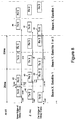
- Figure 8 shows the frame structure at a UT 4a, 4b for an arbitrary delay class.
- Each 40 ms frame is made up of two 20 ms diversity windows. The burst timings at the Earth and the satellite are explained relative to the frame timing on Earth to which they are referenced.
- Figure 8 illustrates that the transmit and receive bursts remain at least 0.267 ms inside the 20 ms diversity window and retain at least a 0.533 ms separation from each other, even when the UT moves away from the Z-arc, so that, within each delay class, the one-way path delay varies up to +/- 1.4 ms from the Z-arc value.
- Rx burst 40 On the Z-arc, Rx burst 40 is received 11.667 ms after the start of the window and corresponds to a Tx burst initiated at the satellite at 11.667 - PD MID , where PD MID is the Z-arc value ie. the path delay from the satellite to a UT located at the Z-arc.
- a Tx burst 41 is initiated 4.5 slots (30 ms) later. Since slot timing is modulo 40 ms, this is equivalent to the receive burst following the transmit burst by 1.5 slots (10 ms), which explains the existence of Tx burst 42 within the same diversity window as Rx burst 40.
- transmit must follow receive because time and frequency references come from the receive burst.
- Tx burst 42 is received at the satellite at a time 1.667 + PD MID .
- the Rx burst 43 is received 1.4 ms before Rx burst 40.
- Tx burst 44 is sent 32.8 ms after Rx burst 43. This represents a delay of 4.5 slots plus a correction of 2.8 ms (2 * 1.4 ms) to compensate for the shorter two-way path delay.
- Rx burst 45 is received 1.4 ms after Rx burst 40.
- the corresponding Tx burst 46 is therefore sent 27.2 ms later, being 4.5 slots less a correction of 2.8 ms to compensate for the longer two-way path delay.
- the appropriate offset for Tx burst timing can be obtained by calculating the difference between the actual path delay to the UT and the known Z-arc value representing the delay class to which the UT is allocated.
- the UT merely adds or subtracts twice this difference (for the two-way path delay) from the basic 4.5 slot (30 ms) delay after the Tx burst is received.
- this offset which has a maximum value of +/- 2.8 ms, can be calculated by the SBS 20 and periodically sent to the UT 4a, 4b.
- the SBS 20 knows the Z-arc value corresponding to the delay class to which the UT 4a, 4b has been allocated. It can determine its own delay to a satellite 3a, 3b by sending and receiving loop-back transmissions. Other delays within the system can be measured or details obtained from the relevant equipment manufacturer, for example, in the case of transponder delays, from the satellite manufacturer, and this information supplied to the SBS 20. Since the SBS 20 knows the various offsets applied by the UT between the Rx and Tx burst, it can then use a received burst from the UT to calculate the actual path delay to the UT.
- time slot 3 in the TDMA structure occurs 20 ms after slot 0, it can be seen that the slot 3 Tx and Rx bursts fit within a 20 ms diversity window contiguous with the first window.
- the same UT can therefore simultaneously use TDMA slot 3 for a diversity link via a second spot beam, either via the same satellite for make-before-break beam handover, or via a second satellite.
- Similar frame structures can be produced for paired slots 1 and 4, and 2 and 5, which are delayed from slot 0 by the appropriate multiple of slot length.
- a UT 4a, 4b Before initiating radio access, a UT 4a, 4b seeks to acquire system time and frequency from a high power Control Channel (Broadcast Control Channel - BCCH) carrying Broadcast Network information.
- the BCCH channel is transmitted using a different carrier frequency to the traffic channels and operates at, for example, +4.5 dB compared to the nominal power for a traffic channel. Acquisition involves using, for example, power-profile analysis on the BCCH signal.
- the UT 4a transmits a formatted burst in a prescribed time slot on a prescribed random access channel (RACH) carrier frequency.
- RACH random access channel
- the relevant SBS searches for and acquires the UT RACH burst timing.
- the SBS Controller 21 requests resources for the UT from the local resource pool maintained by its Local SRMC 22.
- the assignment of a traffic channel is then sent to the UT on an access grant channel (AGCH).
- AGCH access grant channel
- the UT 4a is more than 1.4ms from the Z-arc 43 of the cell 40.
- the TDMA timing structure set out in Figure 8 cannot therefore support communications for the UT 4a via the cell 40.
- the SBS 20 determines the position of the UT 4a using conventional time and frequency measurements.
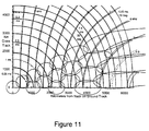
- Figure 11 shows the concept of delay/Doppler position location. Constant Doppler contours on Earth are shown at 1kHz intervals and constant path delay contours at 1ms intervals superimposed onto a beam pattern. The intersection of two contours determines UT position. All the contours are double lines, separated by representative errors of + /-10 ⁇ s delay and +/-30Hz Doppler error. There is a high probability that the position of the UT lies inside the parallelogram at the #-shaped double-contour intersections.
- the true position can be resolved by knowing which beam the UT is in or is apparently in.
- the UT position can be determined on the basis of received signal delays via two or more satellites or on the basis of the Doppler shifts in signals received via a plurality of satellites.
- the SBS 20 can work out the actual path delay between the satellite and the UT by knowing the received RACH time and various fixed offsets. The SBS 20 can then determine the difference between the satellite-UT delay and the delay to the Z-arc in the selected cell, or to the nearest Z-arc if the cell has more than one. If this difference exceeds the maximum permissible figure of 1.4ms, then the UT cannot be supported via a dedicated radio resource in the cell it has selected for access and the SBS 20 can prevent access by the UT through cell 40, by refusing to assign a traffic channel to the UT on the AGCH channel, instead sending a message indicating that the UT is outside the cell limits.
- the SBS 20 can use the calculated position of the terminal and knowledge of the Z-arc positions and velocities to predict when it will be able to allocate dedicated resources in the cell 40 to the UT.
- This calculated time can be sent to the UT on the AGCH channel.
- the UT then cannot access the system through the cell 40 for that time, although this does not preclude the UT from accessing the system through another cell which may have a lower received signal strength. Effectively the cell 40 is temporarily barred for access.
- the SBS 20 carries out comparisons of the actual time delay to the UT with respect to other cells, for example cell 41. On this basis, the SBS 20 may determine that the UT lies within the delay class based on the Z-arc 44. The UT can then be notified by SBS 20 through an AGCH channel that access is possible via cell 41.
- the SBS 20 pre-corrects the forward-link frame timing of the Tx bursts at the satellite to achieve zero frame timing offset on Earth along the Z-arc.
- the UT locks to the corresponding received Rx burst timing and pre-corrects and transmits its return-link Tx burst 4.5 slots +/- up to 2.8 ms later so as to maintain nominally zero timing at the satellite.
- the SBS 20 periodically, for example, once per minute, sends new timing offsets to the UT, based on continuing measurement of return-link burst timing.
- a UT When the UT reaches the edge of a delay class, it is notified by the SBS to hand over to a new delay class.
- a UT in central beams a UT can remain in the same delay class through seven beam handovers, while in edge beams a UT can remain in the same beam for three delay-class handovers.
- TDMA timing constraints and timing Z-arcs different or additional constraints may also need to be met to ensure that the correct cell to be used by the UT can be identified.
- a constraint also exists in the frequency domain with regard to compensating for Doppler effects.
- frequency pre-corrections are referenced to a plurality of frequency Z-arcs, each of which define a zero-offset on Earth from a predetermined nominal signal Doppler shift at the frequency Z-arc.
- the maximum differential Doppler shift from the nominal value at a frequency Z-arc is +/- 1.1 kHz.
- the SBS 20 calculates both delay and Doppler shift values for the UT, which define the position of the UT, and then determines whether the timing and frequency Z-arcs lie within 1.4 ms and 1.1 kHz respectively of the calculated values. Radio resources will be allocated to the UT via the selected cell only if both these constraints are met.
Landscapes
- Engineering & Computer Science (AREA)
- Physics & Mathematics (AREA)
- Astronomy & Astrophysics (AREA)
- Aviation & Aerospace Engineering (AREA)
- General Physics & Mathematics (AREA)
- Computer Networks & Wireless Communication (AREA)
- Signal Processing (AREA)
- Mobile Radio Communication Systems (AREA)
- Radio Relay Systems (AREA)
- Telephonic Communication Services (AREA)
Priority Applications (2)
| Application Number | Priority Date | Filing Date | Title |
|---|---|---|---|
| EP98304655A EP0964531A1 (de) | 1998-06-12 | 1998-06-12 | Zellselektion in einer mobilen Satelliten Anordnung mit Teilnehmer Ortsbestimmung durch Messung der Signallaufzeit und Dopplerverschiebung |
| JP11144070A JP2000068917A (ja) | 1998-06-12 | 1999-05-24 | 呼の選択方法およびそのためのシステム |
Applications Claiming Priority (1)
| Application Number | Priority Date | Filing Date | Title |
|---|---|---|---|
| EP98304655A EP0964531A1 (de) | 1998-06-12 | 1998-06-12 | Zellselektion in einer mobilen Satelliten Anordnung mit Teilnehmer Ortsbestimmung durch Messung der Signallaufzeit und Dopplerverschiebung |
Publications (1)
| Publication Number | Publication Date |
|---|---|
| EP0964531A1 true EP0964531A1 (de) | 1999-12-15 |
Family
ID=8234870
Family Applications (1)
| Application Number | Title | Priority Date | Filing Date |
|---|---|---|---|
| EP98304655A Withdrawn EP0964531A1 (de) | 1998-06-12 | 1998-06-12 | Zellselektion in einer mobilen Satelliten Anordnung mit Teilnehmer Ortsbestimmung durch Messung der Signallaufzeit und Dopplerverschiebung |
Country Status (2)
| Country | Link |
|---|---|
| EP (1) | EP0964531A1 (de) |
| JP (1) | JP2000068917A (de) |
Families Citing this family (3)
| Publication number | Priority date | Publication date | Assignee | Title |
|---|---|---|---|---|
| CN106100718B (zh) * | 2016-05-30 | 2018-11-16 | 西安电子科技大学 | 基于时变图的空间信息网络资源表征方法 |
| KR20230092825A (ko) * | 2020-10-22 | 2023-06-26 | 삼성전자주식회사 | 위성 네트워크에서 천체력 기반 셀 재선택 과정을 수행하는 방법 및 장치 |
| EP4447573A4 (de) * | 2021-12-10 | 2025-09-24 | Ntt Docomo Inc | Endgerät und meldeverfahren |
Citations (7)
| Publication number | Priority date | Publication date | Assignee | Title |
|---|---|---|---|---|
| US5412389A (en) * | 1993-08-11 | 1995-05-02 | Motorola, Inc. | Multibeam position ambiguity resolution |
| US5515062A (en) * | 1993-08-11 | 1996-05-07 | Motorola, Inc. | Location system and method with acquisition of accurate location parameters |
| US5552795A (en) * | 1994-05-03 | 1996-09-03 | Motorola, Inc. | Location determination method and system using multi-beam satellites |
| EP0803742A2 (de) * | 1996-04-25 | 1997-10-29 | Trw Inc. | Verfahren und Gerät zur Positionsbestimmung für satellitengestütztes Telekommunikationssystem |
| EP0808034A2 (de) * | 1996-05-14 | 1997-11-19 | Trw Inc. | Verfahren und Gerät zur Steuerung der Rufweiterreichung in einer Satellitentelekommunikationsanordnung |
| EP0828353A2 (de) * | 1996-09-09 | 1998-03-11 | ICO Services Ltd. | Registrationsverfahren und -gerät in einer mobilen Kommunikationsanordnung |
| EP0845874A2 (de) * | 1996-12-02 | 1998-06-03 | TRW Inc. | Verfahren und Gerät zur Geolokalisierung in Satellitentelekommunikationsanordnung |
-
1998
- 1998-06-12 EP EP98304655A patent/EP0964531A1/de not_active Withdrawn
-
1999
- 1999-05-24 JP JP11144070A patent/JP2000068917A/ja not_active Withdrawn
Patent Citations (7)
| Publication number | Priority date | Publication date | Assignee | Title |
|---|---|---|---|---|
| US5412389A (en) * | 1993-08-11 | 1995-05-02 | Motorola, Inc. | Multibeam position ambiguity resolution |
| US5515062A (en) * | 1993-08-11 | 1996-05-07 | Motorola, Inc. | Location system and method with acquisition of accurate location parameters |
| US5552795A (en) * | 1994-05-03 | 1996-09-03 | Motorola, Inc. | Location determination method and system using multi-beam satellites |
| EP0803742A2 (de) * | 1996-04-25 | 1997-10-29 | Trw Inc. | Verfahren und Gerät zur Positionsbestimmung für satellitengestütztes Telekommunikationssystem |
| EP0808034A2 (de) * | 1996-05-14 | 1997-11-19 | Trw Inc. | Verfahren und Gerät zur Steuerung der Rufweiterreichung in einer Satellitentelekommunikationsanordnung |
| EP0828353A2 (de) * | 1996-09-09 | 1998-03-11 | ICO Services Ltd. | Registrationsverfahren und -gerät in einer mobilen Kommunikationsanordnung |
| EP0845874A2 (de) * | 1996-12-02 | 1998-06-03 | TRW Inc. | Verfahren und Gerät zur Geolokalisierung in Satellitentelekommunikationsanordnung |
Also Published As
| Publication number | Publication date |
|---|---|
| JP2000068917A (ja) | 2000-03-03 |
Similar Documents
| Publication | Publication Date | Title |
|---|---|---|
| US5463400A (en) | Method and apparatus for synchronizing to a multi-beam satellite TDMA communication system | |
| US7801520B2 (en) | Methods and systems for configuring satellite antenna cell patterns in response to terrestrial use of satellite frequencies | |
| EP0772922B1 (de) | Mobiles tdma satellitenkommunikationssystem mit mehrstrahlantenne | |
| US6684057B2 (en) | Systems and methods for terrestrial reuse of cellular satellite frequency spectrum | |
| US7664460B2 (en) | Systems and methods for terrestrial reuse of cellular satellite frequency spectrum in a time-division duplex and/or frequency-division duplex mode | |
| US20030054761A1 (en) | Spatial guardbands for terrestrial reuse of satellite frequencies | |
| US5574969A (en) | Method and apparatus for regional cell management in a satellite communication system | |
| AU2002329831A1 (en) | Modifying satellite antenna cell patterns in response to terrestrial reuse of satellite frequencies | |
| AU2002329697A1 (en) | Spatial guardbands for terrestrial reuse of satellite frequencies | |
| EP0737388A1 (de) | Verfahren zur adaptiven nachfragebasierten kanalwiederverwendung für telekommunikationsanordnungen | |
| US6332069B1 (en) | Apparatus and method for grouping carriers to minimize the occurrence of call blocking in a satellite-based communications network | |
| EP0954117A1 (de) | Übertragungsqualitätsberichtsystem | |
| EP0920143A1 (de) | Messung und Übertragung der Eigenschaften von Signalen durch ein mobiles Satelliten Endgerät unter Verwendung eines Kommunikationsburst eines TDMA Rahmens | |
| EP1033582A1 (de) | Ortbestimmung von Mobilstationen in einem mobilen Satellitentelefonsystem | |
| EP0858176A1 (de) | Verfahren zur Herstellung einer Abbildung von elektromagnetischer Strahlung und seine Anwendung in einem mobilen Satellitentelefonsystem | |
| EP0964531A1 (de) | Zellselektion in einer mobilen Satelliten Anordnung mit Teilnehmer Ortsbestimmung durch Messung der Signallaufzeit und Dopplerverschiebung | |
| EP0967739A1 (de) | Zelleigenschaftsmessung in Idle Modus und Übertragung zum Zentral bei Rufbegin | |
| EP0935351A1 (de) | Funkmittel Verwaltung in einem mobilen Satelliten Telefon System | |
| EP0944183A1 (de) | Betriebsmittelverwaltung von Satelliten | |
| EP1050979A1 (de) | Verfahren zur intelligenten Zellenauswahl mittels Aufenthaltsdaten in zellularen Satellitensystemen | |
| EP1021002A1 (de) | Funkverbindungssteuerung für Diversity-Betrieb | |
| EP1041741A1 (de) | Zeitüberschreitung von Funkverbindung | |
| EP1011209A1 (de) | Zellauswahl in einer mobilen Radiocommunicationsanordnung entsprechend der Empfangsqualität | |
| CA2177077C (en) | Methods of demand-based adaptive channel reuse for telecommunication systems | |
| EP1041835A1 (de) | Von einer mobilen Station ausgehender Verbindungsaufbau |
Legal Events
| Date | Code | Title | Description |
|---|---|---|---|
| PUAI | Public reference made under article 153(3) epc to a published international application that has entered the european phase |
Free format text: ORIGINAL CODE: 0009012 |
|
| AK | Designated contracting states |
Kind code of ref document: A1 Designated state(s): DE FI FR GB NL SE |
|
| AX | Request for extension of the european patent |
Free format text: AL;LT;LV;MK;RO;SI |
|
| 17P | Request for examination filed |
Effective date: 20000614 |
|
| AKX | Designation fees paid |
Free format text: AT BE CH CY DE DK LI |
|
| RBV | Designated contracting states (corrected) |
Designated state(s): DE FI FR GB NL SE |
|
| STAA | Information on the status of an ep patent application or granted ep patent |
Free format text: STATUS: THE APPLICATION IS DEEMED TO BE WITHDRAWN |
|
| 18D | Application deemed to be withdrawn |
Effective date: 20030103 |