EP0964546A2 - Netzwerkverwaltungssystem - Google Patents
Netzwerkverwaltungssystem Download PDFInfo
- Publication number
- EP0964546A2 EP0964546A2 EP99110146A EP99110146A EP0964546A2 EP 0964546 A2 EP0964546 A2 EP 0964546A2 EP 99110146 A EP99110146 A EP 99110146A EP 99110146 A EP99110146 A EP 99110146A EP 0964546 A2 EP0964546 A2 EP 0964546A2
- Authority
- EP
- European Patent Office
- Prior art keywords
- network
- information
- equipment
- management system
- physical
- Prior art date
- Legal status (The legal status is an assumption and is not a legal conclusion. Google has not performed a legal analysis and makes no representation as to the accuracy of the status listed.)
- Withdrawn
Links
Images










Classifications
-
- H—ELECTRICITY
- H04—ELECTRIC COMMUNICATION TECHNIQUE
- H04L—TRANSMISSION OF DIGITAL INFORMATION, e.g. TELEGRAPHIC COMMUNICATION
- H04L41/00—Arrangements for maintenance, administration or management of data switching networks, e.g. of packet switching networks
- H04L41/02—Standardisation; Integration
- H04L41/0213—Standardised network management protocols, e.g. simple network management protocol [SNMP]
-
- H—ELECTRICITY
- H04—ELECTRIC COMMUNICATION TECHNIQUE
- H04L—TRANSMISSION OF DIGITAL INFORMATION, e.g. TELEGRAPHIC COMMUNICATION
- H04L41/00—Arrangements for maintenance, administration or management of data switching networks, e.g. of packet switching networks
- H04L41/02—Standardisation; Integration
- H04L41/024—Standardisation; Integration using relational databases for representation of network management data, e.g. managing via structured query language [SQL]
-
- H—ELECTRICITY
- H04—ELECTRIC COMMUNICATION TECHNIQUE
- H04L—TRANSMISSION OF DIGITAL INFORMATION, e.g. TELEGRAPHIC COMMUNICATION
- H04L41/00—Arrangements for maintenance, administration or management of data switching networks, e.g. of packet switching networks
- H04L41/02—Standardisation; Integration
- H04L41/0246—Exchanging or transporting network management information using the Internet; Embedding network management web servers in network elements; Web-services-based protocols
- H04L41/0253—Exchanging or transporting network management information using the Internet; Embedding network management web servers in network elements; Web-services-based protocols using browsers or web-pages for accessing management information
-
- H—ELECTRICITY
- H04—ELECTRIC COMMUNICATION TECHNIQUE
- H04L—TRANSMISSION OF DIGITAL INFORMATION, e.g. TELEGRAPHIC COMMUNICATION
- H04L41/00—Arrangements for maintenance, administration or management of data switching networks, e.g. of packet switching networks
- H04L41/04—Network management architectures or arrangements
- H04L41/046—Network management architectures or arrangements comprising network management agents or mobile agents therefor
-
- H—ELECTRICITY
- H04—ELECTRIC COMMUNICATION TECHNIQUE
- H04L—TRANSMISSION OF DIGITAL INFORMATION, e.g. TELEGRAPHIC COMMUNICATION
- H04L41/00—Arrangements for maintenance, administration or management of data switching networks, e.g. of packet switching networks
- H04L41/40—Arrangements for maintenance, administration or management of data switching networks, e.g. of packet switching networks using virtualisation of network functions or resources, e.g. SDN or NFV entities
-
- Y—GENERAL TAGGING OF NEW TECHNOLOGICAL DEVELOPMENTS; GENERAL TAGGING OF CROSS-SECTIONAL TECHNOLOGIES SPANNING OVER SEVERAL SECTIONS OF THE IPC; TECHNICAL SUBJECTS COVERED BY FORMER USPC CROSS-REFERENCE ART COLLECTIONS [XRACs] AND DIGESTS
- Y10—TECHNICAL SUBJECTS COVERED BY FORMER USPC
- Y10S—TECHNICAL SUBJECTS COVERED BY FORMER USPC CROSS-REFERENCE ART COLLECTIONS [XRACs] AND DIGESTS
- Y10S707/00—Data processing: database and file management or data structures
- Y10S707/953—Organization of data
- Y10S707/959—Network
-
- Y—GENERAL TAGGING OF NEW TECHNOLOGICAL DEVELOPMENTS; GENERAL TAGGING OF CROSS-SECTIONAL TECHNOLOGIES SPANNING OVER SEVERAL SECTIONS OF THE IPC; TECHNICAL SUBJECTS COVERED BY FORMER USPC CROSS-REFERENCE ART COLLECTIONS [XRACs] AND DIGESTS
- Y10—TECHNICAL SUBJECTS COVERED BY FORMER USPC
- Y10S—TECHNICAL SUBJECTS COVERED BY FORMER USPC CROSS-REFERENCE ART COLLECTIONS [XRACs] AND DIGESTS
- Y10S707/00—Data processing: database and file management or data structures
- Y10S707/99941—Database schema or data structure
- Y10S707/99944—Object-oriented database structure
- Y10S707/99945—Object-oriented database structure processing
Definitions
- the present invention relates to a network management technique suited advantageously for employment in a network in which media sharing type infrastructures and media switch type infrastructures coexist mixedly.
- a router apparatus and a bridge apparatus have been widely used as the means for controlling communication traffics by dividing a network into a plurality of segments.
- a high-speed/wide-band switch apparatus of ATM type (Asynchronous Transfer Mode) has also been developed and used for practical applications.
- IEEE 802.1q Standards published by the Institute of Electrical and Electronics Engineers (IEEE) and disclosed in Japanese Unexamined Patent Application Publication No. 130421/1997 (JP-A-9-130421) as well, it is known to implement virtual networks, i.e., logical network segments for every network port under the control of the switch apparatus.
- virtual networks i.e., logical network segments for every network port under the control of the switch apparatus.
- Another object of the present invention is to provide a network management system implemented by adopting the network management technique mentioned above.
- Yet another object of the present invention is to provide individual apparatuses required for constituting the above-mentioned system.
- the present invention is directed to a network management system for managing a computer network in which a media switching type infrastructure and a media sharing type infrastructure are combined coexistently.
- a database for network management in which correspondences are established among information concerning physical connections of equipment on the network, information concerning logical network configuration such as that of virtual network and information concerning users who make use of the network.
- management of the network including a plurality of virtual networks realized in accordance with respective schemes can be facilitated because the setup status of the virtual networks can be referenced, surveyed or altered easily in a consolidated manner owing to the provision of the service-destined database which is capable of storing the information concerning the physical interconnections of network equipment, the information concerning the logical virtual network configuration and the user information.
- a display unit which is capable of displaying the information concerning the physical network, the information concerning the logical network and the user information in the form of tree-structure type directory data.
- a display means which is capable of disposing the physical network information, the logical network information and the user information on different planes, respectively, for displaying the information on all the planes three-dimensionally within a single frame.
- an identification means for identifying discriminatively the entities of individual equipment on the network as well as interconnection relations thereof by using physical addresses allocated inherently to network ports, respectively.
- a search or retrieve means which is capable of searching or retrieving the information of the physical addresses inherent to the network ports, respectively, in response to queries about the logical addresses.
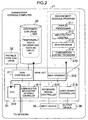
- a computer 21 serving as a management console (hereinafter referred to as the management console computer), a computer 22 serving as a supervising manager (hereinafter referred to as the supervising manager computer), a server computer 23 serving as a management platform (hereinafter referred to as the management platform computer) for providing equipment managing environment such as typified by SNMP (Simple Network Management Protocol), a computer 24 for directory services (hereinafter referred to as the directory server computer) and management-subjected equipment 25 which is subject to management.
- the management console computer serving as a management console
- a computer 22 serving as a supervising manager (hereinafter referred to as the supervising manager computer)
- a server computer 23 serving as a management platform (hereinafter referred to as the management platform computer) for providing equipment managing environment such as typified by SNMP (Simple Network Management Protocol)
- SNMP Simple Network Management Protocol
- the directory server computer for directory services
- management-subjected equipment 25 which is subject to management.
- management console programs 210 which run on the management console computer 21, there can be mentioned such program modules as a display processing module 211, an input/output control module 212, a web browser module 213 and a communication control processing module 214.
- the display processing module 211 serves for realizing the function of displaying network implementation statuses to a network manager.
- the input/output control module 212 serves for realizing the function of allowing the network manager to input commands.
- the web browser module 213 serves for providing a standard environment for the management console.
- the communication control processing module 214 serves for the function for enabling dynamic information exchange between the management console computer 21 and the supervising manager computer 22.
- security function such as encrypted communication facility may be incorporated in the communication control processing module 214.
- the display processing module 211, the input/output control module 212 and the communication control processing module 214 running on the management console computer 21 can be down-loaded from the supervising manager computer 22 as the program modules designed to run on the web browser module 213 of the management console computer 21 by making use of the function of the web browser module 213.
- the module required to be loaded in the management console computer 21 at the least may be only the web browser module 213.
- the display processing module 211 and others can be so implemented as to run on the web browser module 213 of given type through combination with HTML (Hyper Text Markup Language) or the like.
- the display processing module 211 and others can be so prepared as to run on the computers of large variety so long as the WWW (Worldwide Web) can be utilized.
- the communication control processing module 214 capable of running on the management console computer 21
- module conforming to other publicly known standards such as FTP (File Transfer Protocol) can be loaded or packaged.
- the supervising manager program 220 destined to run on the supervising manager computer 22, there can be mentioned such program modules as a communication control processing module 222, a web server module 223, a database control module 224, a directory service control module 225, an equipment control procedure generating module 226, an equipment control communication processing module 227 and an equipment discriminating or identifying function module 228. Further provided is an equipment setup information database (DB) 221 which is managed by the supervising manager computer 22.
- DB equipment setup information database
- the communication control processing module 222 is so designed as to allow dynamic information exchange with the management console computer 21.
- the web server module 223 serves for presenting static information display service to the management console computer in cooperation with the web browser module 213.
- the database control module 224 is designed for storing equipment setup data required for management in the equipment setup information database (DB) 221.
- the directory service control module 225 is so designed as to realize retrieval or search function for equipment management data, network user information, etc., by taking into account the structure of equipment and/or hierarchical structure of enterprise organization.
- the equipment control procedure generating module 226 serves for developing a setup altering procedure for the network equipment to an equipment setting sequence by making use of the equipment setup information database 221.
- the equipment control communication processing module 227 serves to send the equipment setting sequence information to the management platform computer 23.
- the equipment identifying function module 228 is designed to identify discriminatively network equipment. Incidentally, concerning the hardware structure of the supervising manager computer 22, description will be made later on by referring to Fig. 3.
- an equipment control procedure execution module 231 As the management platform programs 230 which are destined to run on the management platform computer 23, there are provided an equipment control procedure execution module 231 and an SNMP (Simple Network Management Protocol) manager module 232.
- the equipment control procedure execution module 231 is so programmed as to control the execution of the equipment setting sequence sent from the supervising manager computer 22.
- the SNMP manager module 232 sends the information for management to the equipment to be set up (hereinafter referred to as the setup-destined equipment) in accordance with the SNM protocol.
- a corresponding manager designed for sending equipment setup information by using a relevant protocol may be disposed similarly to the SNMP manager module 232 to thereby support the relevant protocol.
- hardware structure of the management platform computer 23 will be described later on by reference to Fig. 4.
- a directory database (DB) 241 is managed by the directory server computer 24.
- the directory server module 242 is in charge of controlling the directory database 241.
- the communication control module 243 is designed to control the communication with the supervising manager computer 22.
- equipment control program modules such as an equipment control module 251, a management information base 252 and an SNMP (Simple Network Management Protocol) agent module 253.
- equipment control program modules such as an equipment control module 251, a management information base 252 and an SNMP (Simple Network Management Protocol) agent module 253.
- SNMP Simple Network Management Protocol
- the equipment control module 251 is programmed to realize the functions of the equipment itself.
- the management information base 252 is standardized for realizing the network management function through the medium of SNMP or the like.
- the SNMP agent module 253 performs send/receive processings involved in transferring information stored in the management information base 252 with the SNMP manager module 232.
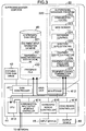
- the management console computer 21 is realized in a structure similar to that of the conventional computer and is comprised of a main unit 31, a portable-type disk drive 32 such as a floppy disk drive or the like, a stationary disk storage 33, an input device 35 such as a keyboard and/or a mouse, and an output device 36 such as a display device.
- the main unit 31 in turn is comprised of a disk controller 311, a main storage 312, a central processing unit (or central arithmetic unit) 313, a communication input/output interface controller 314, a keyboard/mouse controller 315 and a video board controller 316.
- the management console computer 21 responds to the input/output from/to the network 20 to thereby fetch the management console program 210 including the program modules 211, 212, 213 and 214 for the management console to store them in the main storage 312.
- the stationary disk drive 33 is provided, it is utilized for the input/ output of temporarily saved information 331 such as cache data, etc.
- the management console program 210, the program modules 211, 212 and 214 except for the web browser module 213 can be delivered from the network 20, and thus the stationary disk storage 33 illustrated as being provided for the management console computer 21 is not always the indispensable component for the network management system according to the present invention.
- the supervising manager computer 22 is also realized in a structure similar to that of the conventional computer and comprised of a main unit 41, a portable-type disk drive 42 such as a floppy disk drive, a fixed or stationary disk drive 43, an input device 45 such as a keyboard and/or a mouse, and an output device 46 such as a display device.
- the stationary disk drive 43 stores therein the equipment setup information database 221, a temporarily saved information 431 such as cached data and a program file 432.
- the main unit 41 in turn is comprised of a disk controller 411, a main storage 412, a central processing unit (central arithmetic unit) 413, a communication input/output interface controller 414, a keyboard/mouse controller 415 and a video-board controller 416.
- the supervising manager computer 22 a group of the program modules for the supervising manager computer and a group of the program modules for the management console computer are held in the stationary disk drive 43 in the form of program files 432.
- the group of the program modules for the supervising manager computer 22 are executed on the main storage 412 of the supervising manager computer 22.
- the supervising manager computer 22 sends a group of the program modules 21 for the management console computer to the latter through the medium of the communication input/output interface controller 414. Further, send/receive requests issued on a real time basis are processed in response to user's operation or manipulation for the supervising manager computer 22.
- the supervising manager computer 22 performs communication with the management platform computer 23 for acquisition and supply of the network equipment setup information. This communication is also performed through the medium of the communication input/output interface controller 414 by way of the network 20 similarly to the communication with the management console computer 21.
- the supervising manager computer 22 and the management platform computer 23 need not always be provided independently.
- the functions of these computers 22 and 23 may be realized by using one and the same computer hardware. In that case, the data transfer mentioned above can be realized through a data bus provided internally of the computer mentioned just above without need for intervention of the network.
- the management platform computer 23 is also realized in a structure of the conventional computer and comprised of a main unit 51, a portable-type disk drive 52 such as a floppy disk drive, a fixed or stationary disk drive 53, an input device 55 such as a keyboard and/or a mouse, and an output device 56 such as a display device.
- the stationary disk drive 53 stores therein a temporarily saved information 531 such as cached data and a program file 532.
- the main unit 51 is comprised of a disk controller 511, a main storage 512, a central processing unit 513, a communication input/output interface controller 514, a keyboard/mouse controller 515 and a video-board controller 516.
- the communication channel established or secured between the management console program 210 and the supervising manager program 220 includes a communication channel secured between the web server module 223 and the web browser module 213 for transmission of programs, and a communication channel established between the communication control processing modules 214 and 222 in response to a data send/receive request issued on a real time basis upon activation of the program.
- a conventional communication protocol such as "HTTP (Hyper Text Transfer Protocol)" or "Socket" can be used as "HTTP (Hyper Text Transfer Protocol)" or "Socket" can be used.
- a communication channel for enabling search and update processing for the directory database 241.
- the communication protocol there may be employed a standard protocol such as DAP (Directory Access Protocol) or LDAP (Lightweight Directory Access Protocol).
- another communication channel is established between the supervising manager program 220 and the management platform program 230, more specifically, between the equipment control procedure generating module 226 and the equipment control procedure execution module 231.
- the communication protocol there can be employed a transfer protocol such as "ftb" and a data exchange protocol such as a data stream processing communication protocol.
- an inter-process communication mechanism such as a pipe can be employed alternatively as the communication channel.
- communication channels are secured between the SNMP manager module 232 of the management platform program 230 and individual SNMP agents 253 of management-subjected equipment control programs 250a, 250b, ..., and 250n, respectively.
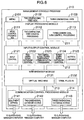
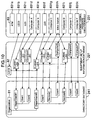
- the management console program 210 is constituted by the display processing module 211, the input/output control module 212, the web browser module 213 and the communication control processing module 214, as shown in Fig. 1.
- the management console program 210 can be functionally classified globally into three types of application modules in dependence on the contents to be displayed on the output device 36 (Fig. 2) which serves as a user interface for the management console computer 21. They are a menu module 2101, a two-dimensional tree view module 2102 and a three-dimensional tree view module 2103.
- a menu control processing module 2111 which is implemented with a web-destined script language such as HTML (Hyper Text Markup Language), Java Script or the like, a two-dimensional tree control processing module 2112 implemented with a web-destined program language and a three-dimensional view control processing module 2113 implemented with a script language for the three-dimensional display such as VRML (Virtual Reality Modeling Language) or the like.
- a web-destined script language such as HTML (Hyper Text Markup Language), Java Script or the like
- a two-dimensional tree control processing module 2112 implemented with a web-destined program language
- a three-dimensional view control processing module 2113 implemented with a script language for the three-dimensional display such as VRML (Virtual Reality Modeling Language) or the like.
- an input control module 2121 for controlling inputs from the menu as displayed
- a two-dimensional database control module 2122 for requesting the supervising manager for input/output of data for the two-dimensional display
- a two-dimensional/three-dimensional communication processing module 2123 for performing communication control for interlocking operations of the two-dimensional display and the three-dimensional display
- a three-dimensional database control module 2124 for requesting the supervisory manager for input/output of data for the three-dimensional display
- an action library module 2125 for altering contents of the three-dimensional display in accordance with the commands inputted by the user.
- a virtual machine module 2131 for executing a web-destined program on the web browser
- a VRML (Virtual Reality Modeling Language) plug-in module 2132 designed for executing actual display processing by processing the script language for the three-dimensional display.
- an equipment setting module 2141 for enabling to manipulate directly the function of the management platform from the menu
- a two-dimensional database (DB) access module 2142 for actually transferring to the supervisory manager a request issued by the two-dimensional database control module 2122 to thereby acquire the result thereof
- a three-dimensional database access module 2143 for actually transferring to the supervisory manager a request issued by the three-dimensional database control module 2124 to thereby acquire the result thereof.
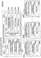
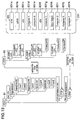
- the supervising manager program 220 is constituted by such program modules as the communication control processing module 222, the web server module 223, the database control module 224, the directory service control module 225, the equipment control procedure generating module 226, the equipment control communication processing module 227 and the equipment identifying function module 228, as described hereinbefore by reference to Fig. 1.
- the equipment control procedure generating module 226 in turn is comprised of an equipment control module 226a and an equipment setting module 226b for relaying or repeating to the management platform the information which is required for directly manipulating the management platform computer 23 from the management console computer 21.
- the constituent or component modules for implementing the equipment communication control processing module 222 there are provided for performing communication processing with the display processing module 211 of the management console computer 21 a two-dimensional database interface module 2221 for receiving commands inputted from the two-dimensional database access module 2142 shown in Fig. 6, a three-dimensional database interface module 2222 for receiving commands inputted from the three-dimensional database access module 2143, a data conversion module 2223 for converting various types of information supplied from the equipment setup information database 221 and the directory service program 240 into a format suited for data interfacing with the management console program 210, and a database access control module 2224 for performing a processing of distributing the various database access requests to the pertinent database control modules for the equipment setup information database 221, the directory database 241 and the like.
- a database function such as an SQL (Structured Query Language) server 2211 or the like.
- a database function such as a view information control module 2241 stored as the data common to the two-dimensional display and the three-dimensional display, an attribute information control module 2242 for controlling the detail attribute information of the management-subjected equipment, and an SQL (Structured Query Language) server 2243 designed for database control.
- a view information control module 2241 stored as the data common to the two-dimensional display and the three-dimensional display
- an attribute information control module 2242 for controlling the detail attribute information of the management-subjected equipment
- an SQL (Structured Query Language) server 2243 designed for database control.
- a directory service control interface module 2251 such as LDAP (Lightweight Directory Access Protocol), API (Application Program Interface) or the like for issuing a request for data search/update or the like to the directory service.
- LDAP Lightweight Directory Access Protocol
- API Application Program Interface
- an SNMP command sequence generating module 2261 for generating an equipment control sequence in the form of a string of commands conforming to SNMP (Simple Network Management Protocol) representative of the equipment control protocol, to thereby supply the control sequence to the management platform computer 23.
- SNMP Simple Network Management Protocol
- the equipment control communication processing module 227 there may be mentioned a gateway function 2271 to the management platform.
- the management platform program 230 includes the equipment control procedure execution module 231 and the SNMP manager module 232, as can be seen in Fig. 1.
- a socket 2311 for receiving communication from the supervising manager computer 22, a database application program interface 2312 for manipulating a local database of the management platform computer 23, and an SNMP application program interface 2313 for enabling manipulation of the SNMP manager 232.
- the SNMP manager 232 has be to equipped with an application program interface function for using an application program interface 2321 when the manager function is employed. Additionally, as other components of the SNMP manager module 232, there are provided a network equipment managing engine 2322, a device managing engine 2323, a local database 2324 for networks object and an SNMP demon 2325 for generating SNMP packets.
- the management-subjected equipment control programs 250a, 250b, ... and 250n are constituted by the equipment control modules 251a, 251b, ... and 251n, the management information bases 252a, 252b, ... and 252n, and the SNMP agents 253a, 253b, ... and 253n, respectively.
- the web browser module 213 of the management console program 210 is activated in a step S61.
- the network management system is activated in a step S62.
- a step S631 the management console program 210 executes download processing of the menu page, while the supervising manager program 220 executes upload processing in a step S641. Then, the menu page is called through communication between the web server 223 of the supervising manager program 220 and the web browser 213 of the management console program 210.
- the supervising manager program 220 executes a processing for searching or retrieving the setup information of the individual network equipment from the equipment setup information database 221.
- the supervising manager program 220 decides in a step S643 whether or not the setup information of all the equipment has been acquired while confirming the existence of the equipment on the network.
- the processing proceeds to a step S647.
- the supervising manager program 220 when it is decided that the setup information of all the equipment has not been acquired yet, the supervising manager program 220 generates a sequence for acquiring the equipment setup intonation (MIB values (Management Information Base values)) in a step S644.
- MIB values Management Information Base values
- the supervising manager program 220 requests the management platform program 230 to execute the setup information acquisition processing in a step S645.
- the management platform program 230 issues the SNMP command to the management-subjected equipment control programs 250, respectively, in response to the request for the setup information acquisition processing issued by the supervising manager program 220 in a step S651.
- Each of the management-subjected equipment control programs 250 executes the equipment setup information (MIB value) acquisition processing in response to the SNMP command from the management platform program 230 in a step S661.
- the equipment setup information (MIB value) as acquired is then sent through the medium of the management platform program 230 to the supervising manager program 220, which receives the information through the processing in the step S645.
- the supervising manager program 220 executes a processing for updating the equipment setup information database on the basis of the equipment setup information as received.
- the updated equipment setup information is sent back to the web server module 223 to be received by the management console program 210 through the upload processing in the step S641 and the download processing in the step S631.
- the supervising manager program 220 executes a processing for generating three-dimensional display data.
- Individual objects appearing in a directory tree structure view 81 representing an organization are packaged or stored in the directory database 241, while individual objects in a tree structure view 82 representing a structure or configuration of the virtual network are packaged in the equipment setup information database 221, wherein correlations are established to individual equipment setup information 83 (831a, ..., and 831k), respectively, which correspond to the individual equipment and the functions thereof determined through the equipment control procedure execution module 231 of the management platform computer 23.
- relations between the users and the individual LEC objects are defined.
- the correspondence relation with the object is indicated by one-to-one correspondence relation.
- the correspondence relation is indicated by a "plural-to-one" correspondence relation.
- the relation can be given by "one-to-plural" correspondence relation.
- the objects 831a, ... and 831k represent object data of the equipment displayed on the physical network, respectively, and are related to the individual objects on the virtual network.
- the relevant equipment for which manipulation should be performed can easily be identified.
- the department to which a user belongs is to be changed, it can be easily determined how to alter or change the configuration of the virtual network or for which of the equipment the alteration of the network configuration is to be performed.
- Object items 85 and object attributes 86 are stored as parts of the main storage 412 of the supervising manager computer 22, wherein the object items 85 represents the data of one object displayed on a given one of the network layers.
- An object identifier 851a is composed of an ID (identifier) of the network layer to which the relevant object belongs and an ID of the object on that network layer.
- Individual information such as object information 851b of the physical network layer, link information 851c for the physical network layers, object information 851d of the virtual network layer, link information 851e for the virtual network layers, object information 851f of the logical network layer, link information 851g for the logical network layers, object information 851h of the directory layer, link information 851i for the directory layers, object information 851j of added layer and link information 851k for the added layer are stored as pointers at respective relevant areas of the main storage 412 storing actually the data of the object attribute database 86 to be used as the association information (relation establishing information) for the other objects in the same network or objects on the other network layers.
- the physical network layer object information 851b may be referenced to make access to the area where the attribute information of that object is stored.
- the information of concern can be obtained.
- the physical network layer link information 851c may be referenced to make access to the area where the object attribute information is stored, to thereby acquire the information of concern.
- object association information such as mentioned above
- information concerning services or the like on the other networks can also be added easily although not described concretely herein.
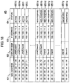
- the address management table 50 for managing the IP address allocation status contains a list of addresses 501 of the IPs which are to be managed with this table as the subjects for the address allocation, information concerning active/reserved/unoccupied statuses of the IP addresses, as designated by reference numeral 502, and information concerning MAC addresses allocated to network ports of the machines or equipment to which the IP addresses have been allocated, as designated by reference numeral 503.
- the address management table 50 is stored in the main storage 412 incorporated in the supervising manager computer 22.
- the active/reserved/unoccupied statuses 502 of the IP addresses can be indicated by the respective records 541a 541b, ... and 541z.
- the IP address "192.168.11.0" of the record 541a is allocated with the MAC address "00:00:00:22:11:42" at the port, indicating that the corresponding IP address is currently in the reserved state, which in turn means that the relevant IP address is not currently being used.
- the IP address "192.168.11.2” is allocated with the MAC address "00:00:00:23:11:55" and is in the active state, i.e., "used or occupied states”. Needless to say, similar management can be performed on the other logical addresses than the IP addresses.
- the management console program 210 executes the directory information acquisition processing for the supervising manager program 220.
- the supervising manager program 220 responds to a directory information acquisition request issued by the management console program 210 to thereby issue a request for search of the directory database 241.
- a step S671 the directory service program 240 makes access to the directory server module 242 in response to the above-mentioned search request to thereby acquire the directory information which is then transferred to the supervising manager program 220.
- the supervising manager program 220 transfers the received directory intonation to the management console program 210 through the processing in a step S648.
- the management console program 210 acquires the directory intonation through the processing in the step S632.
- the data 91, 92 and 93 hierarchized on a group basis are registered in the directory database 241, respectively, at locations determined with reference to other object of a same level in each of the groups. More specifically, of the data 91, the user related information "User Info.”, and the logical network structure information of the virtual network “Virtual Network Info.” and the physical connection information of the equipment and the network "physical Equipment” are registered in a same hierarchical layer.
- the directory "User Info.” for the user-related information has a tree structure in which "Organization” is located at hierarchically lower layer with “Department #1” and “Department #2” being located hierarchically at lower layer than "User Info.”.
- the logical network structure information "Virtual Network Info.” data 92 of tree structure is registered in "Virtual Network Info.” of the data 91, whereby such a tree structure is realized in which "LECS" is disposed at a hierarchically lower layer of "Virtual Network Info.” of the data 91 with "ELAN #1" and “ELAN #2” being located at hierarchically lower layer than "LECS".
- the setup information of the individual equipment, the information of the virtual network structure or configuration and the user management information can be handled as the same type directory service data, and at the same time the relations or associations between the users and the equipment can easily be packaged in association with the individual object data on the directory service.
- the screen of the display device which serves as the output device 36 of the management console computer 21 may be composed of display areas 1901, 1904 and 1905, a control area or field 1903 and others.
- the display area 1901 located at a left-hand side of the display screen the data acquired or read out from the directory database 241 are displayed in a tree structure.
- the user-related information "User Info.” contained in the data 91 described hereinbefore by reference to Fig. 14 is displayed in the area 1901.
- by displaying the menu by clicking a button 1901A it is possible to display equally the logical network configuration information "Virtual Network Info.” or the physical connection information "Physical Equipment” in place of the user-related information "User Info.”.
- a three-dimensional display is generated.
- the three-dimensional display is composed of a user's display plane 1040 for displaying the user-related information, a virtual network display plane 1020 for displaying the logical network configuration information and a physical network display plane 1010 for displaying the physical connection information, details of which will be described later on by reference to Fig. 16.
- a virtual network display plane 1020 for displaying the logical network configuration information
- a physical network display plane 1010 for displaying the physical connection information, details of which will be described later on by reference to Fig. 16.
- the control field 1903 is provided for allowing the sight line for the display area 1904 displayed three-dimensionally.
- the display area 1905 serves as a status display area for displaying the menu of items for manipulation and the current statuses.
- Fig. 15 shows the contents displayed in the three-dimensional display area 1904 described above by reference to Fig. 14.
- the physical network display plane 1010 for displaying the physical interconnection information there is displayed an example of the physical network structure view showing three-dimensionally the physical interconnection relation of the networks handled by the network management system according to the instant embodiment of the invention.
- an ATM (Asynchronous Transfer Mode) switch 1012 there are arrayed in the form of stereoscopic object icons on the three-dimensionally displayed plane 1010, an ATM (Asynchronous Transfer Mode) switch 1012, a router 1013 connected to the ATM switch 1012, a personal computer 1011 on which LECS is running, personal computers 1014a and 1014b on which LES is running, personal computers 1015a, ..., 1015f on which LEC are running, a switch 1016 and connection 1019 to other network, respectively. Further, in order to indicate mutual connections among the machines or equipment, lines indicating the equipment interconnection relations are displayed among the individual object icons.
- ATM Asynchronous Transfer Mode
- Displayed on the virtual network display plane 1020 for displaying the logical network configuration information is a typical virtual network structure view showing three-dimensionally implementation statuses of virtual network segments of the network, as handled by the network management system according to the invention.
- the virtual network display plane 1020 As the virtual network segments are emulated LANs 1027a and 1027b as well as VLANs 1028a and 1028b in the form of closed areas, respectively, wherein servers and clients constituting the virtual network are shown as stereoscopical object icons, respectively.
- the LECS 1021 and the LESs 1024a and 1024b are shown as server objects of the LAN emulation as connected to the ATM while the LESs 1025a, ..., 1025f and the Ethernet switch apparatus 1022 are shown as the client objects, respectively. It can further be seen that lines are displayed for indicating server-client relations between the server objects and the client objects, respectively.
- the user display 1040 is generated in dependence on the users and the departments or sections of an organization to which the users belongs.
- the directory data are displayed three-dimensionally in the form of a directory data structure 81.
- Two departments “Department #1” and “Department #2” mentioned previously by reference to Fig. 10 are shown as the closed areas, respectively.
- sections “Section #1” and “Section #2” are shown in the form of closed areas 1048a and 1048b, respectively.
- the ranking relation among the individual areas and the affiliations of the users are indicated by subsumptive relations among the closed areas, respectively.
- the individual users 1045a, ..., 1045f are disposed within the closed areas indicating the departments or sections to which the users belong, respectively.
- Arrows 1401a; 1401b and 1402a; 1402b represent relations or associations among the objects shown as the stereoscopical object icons in a plurality of network structure views.
- the arrow 1401b indicates that in the virtual network, the user 1045a is a same entity as the LEC computer 1025a which belongs to the virtual segment 1027a.
- the arrow 1401c indicates that in the physical network, the LEC computer 1025a is a same entity as the computer 1015a.
- correspondence relations among the user 1045c, the computer 1025c on the virtual network and the computer 1015a on the physical network are indicated by the arrows 1402b and 1402c, respectively.
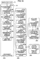
- a step S71 when user inputs a command for alteration or change or modification of the network configuration, processings according to the instant embodiment of the invention is started.
- a step S731 the management console program 210 decides whether or not the user's command indicates alteration of the network configuration. Unless the command indicates the alteration, i.e., when the decision step S731 results in negation "NO", the processing proceeds to a step S733.
- the management console program 210 When the network configuration being set up is to be altered, the management console program 210 messages or informs the supervising manager program 220 of the contents of the alteration.
- the supervising manager program 220 Upon reception of the message informing the alteration, the supervising manager program 220 acquires the contents of alteration in a step S741.
- the supervising manager program 220 searches the equipment setup information database 221 in a step S742.
- the supervising manager program 220 lists up the machines or equipment for which the setup status is to be altered.
- the supervising manager program 220 checks validity of the contents of the alteration as well as the validity of the setup status updating processing in a step S744.
- the supervising manager program 220 In a step S745, the supervising manager program 220 generates a sequence of the equipment setup information (MIB (Management Information Base) values).
- MIB Management Information Base
- the supervising manager computer 22 activates the setup processing while informing the management platform program 230 of the setup processing.
- a step S751 the management platform program 230 issues the SNMP command to the individual management-subjected equipment control programs 250, respectively, in accordance with the setup processing information issued by the supervising manager program 220.
- a step S761 the management-subjected equipment control program 250 executes the setup processing in accordance with the equipment setup information (MIB values) in response to the SNMP command issued by the management platform program 230.
- MIB values equipment setup information
- the supervising manager computer 22 updates the contents of the equipment setup information database 221.
- the supervising manager program 220 issues a request to the directory service program 240 for updating the contents of the directory database 241.
- the directory service program 240 Upon reception of the content updating request mentioned above, the directory service program 240 makes access to the directory server module 242 to update the contents of the directory database 241 in a step S771.
- the supervising manager program 220 terminates the alteration or updating processing in a step S749.
- the management console program Upon reception of the information of completion of the alteration processing, the management console program decides whether or not the contents of display is to be updated in a step S733. When the display is not to be updated, the processing proceeds to a step S736.
- the management console program 210 executes the two-dimensional display program for altering or modifying the content of display, to thereby generate two-dimensional display data on the screen of the output device 36 such as the display device of the management console computer 21 in a step S734.
- the management console program 210 executes the three-dimensional display program to alter the content of display, for thereby generating the three-dimensional display data on the screen of the output device 36 such as the display screen of the management console computer 21.
- the management console program 210 executes the directory display data generating processing for generating the directory display data on the screen of the output device 36 such as the display screen of the management console computer 21.
- the supervising manager program 220 responds to activation of the VLAN topology search by activating a topology search system in a step S911.
- the supervising manager program 220 executes a processing for retrieving the setup information of the individual network equipment.
- the supervising manager program 220 decides in a step S913 whether or not the setup information of all the LANS have been acquired while confirming the interconnection relations of the equipment on all the LANs.
- the processing proceeds to a step S919.
- the supervising manager program 220 activates existing VLAN setup information acquisition processing for saving temporarily the information concerning the current virtual network configuration, whereon request for the acquisition processing of the setup information is issued to the management platform program 230 in a step S914.
- the management platform program 230 issues the SNMP command to the management-subjected equipment control programs 250, respectively, in response to the request for the setup information acquisition processing issued by the supervising manager program 220 in a step S931.
- Each of the management-subjected equipment control programs 250 executes the equipment setup information (MIB value) acquisition processing in response to the SNMP command from the management platform program 230 in a step S941.
- the equipment setup information (MIB value) as acquired is then sent through the medium of the management platform program 230 to the supervising manager program 220, which receives the information through the processing in the step S914.
- the supervising manager program 220 activates the setup processing for the searching or retrieving VLAN and issues a message of the processing for setting the setup information for the management platform program 230.
- the management platform program 230 issues the SNMP command to the individual management-subjected equipment control programs 250, respectively, in accordance with the setup processing information issued by the supervising manager program 220. In that case, the management platform program 230 alters dynamically the virtual networks managed by the equipment by performing the control for retrieving the individual network ports.
- the management-subjected equipment control program 250 executes the setup processing in accordance with the equipment setup information (MIB values) in response to the SNMP command issued by the management platform program 230.
- the equipment setup information MIB values
- information concerning completion of the setup processing is sent to the supervising manager program 220 through the medium of the management platform program 230.
- the supervising manager program 220 executes the MAC address information query processing in a step S916.
- the supervising manager program 220 can grasp the inter-equipment connection relations by retrieving the MAC addresses of the equipment connected to the ports, respectively.
- the supervising manager program 220 executes a processing for restoring the original virtual network configuration after completion of a series of the processings described above.
- the supervising manager computer 22 updates the contents of the equipment setup information database 221.
- the object management table 60 contains a list of MAC addresses 61 employed for identification of the objects, a list of computer names 62 used as the names representing the objects, respectively, a list of logical address allocation statuses 63 indicating the addresses allocated to the individual objects and a list of given statuses 64.
- Each of the objects is identified by the intrinsic MAC address allocated to the port of the equipment and can be managed independent of the allocation status of the logical network addresses.
- the object management table 60 is generated by the supervising manager program 220 and stored in the equipment setup information database 221 of the supervising manager computer 22.
- the supervising manager program 220 makes decision as to whether or not the search has been completed for all the ports. Unless the search has been completed, the steps S914 et seq. are executed repeatedly. When the search has been completed, the VLAN topology search processing comes to an end.
- the interconnection relation of the physical network equipment, logical structure information of the virtual networks and the user information can be stored in the directory service data.
- the setup of the virtual network can be referenced or supervised or altered easily at one location or place in a consolidated manner.
- the configuration of the logical network segments based on the virtual network and the physical network configuration implemented through physical wiring of the equipment can be managed will very high reliability and accuracy while establishing concurrently the correspondences, respectively, to the logical network configurations as viewed from various upper-rank protocols.
- the information concerning the physical interconnection relations among the network equipment, the information concerning the logical virtual network configuration and the user information can be searched and altered in a consolidated manner by using as the key the MAC addresses allocated to the physical network equipment even when the information mentioned above can not be acquired directly by resorting to the SNMP or like means.
- the logical network segment configuration based on the virtual network the physical network configuration as viewed from various upper-rank protocols can be managed while establishing concurrently correspondences thereamong by using as the keys the MAC addresses allocated to the physical network configuration, respectively.
Landscapes
- Engineering & Computer Science (AREA)
- Computer Networks & Wireless Communication (AREA)
- Signal Processing (AREA)
- Databases & Information Systems (AREA)
- Data Exchanges In Wide-Area Networks (AREA)
- Computer And Data Communications (AREA)
- Small-Scale Networks (AREA)
Applications Claiming Priority (2)
| Application Number | Priority Date | Filing Date | Title |
|---|---|---|---|
| JP14932298 | 1998-05-29 | ||
| JP14932298A JP3617770B2 (ja) | 1998-05-29 | 1998-05-29 | ネットワーク管理システム及びネットワーク管理方式 |
Publications (2)
| Publication Number | Publication Date |
|---|---|
| EP0964546A2 true EP0964546A2 (de) | 1999-12-15 |
| EP0964546A3 EP0964546A3 (de) | 2003-09-03 |
Family
ID=15472591
Family Applications (1)
| Application Number | Title | Priority Date | Filing Date |
|---|---|---|---|
| EP99110146A Withdrawn EP0964546A3 (de) | 1998-05-29 | 1999-05-25 | Netzwerkverwaltungssystem |
Country Status (3)
| Country | Link |
|---|---|
| US (2) | US6789090B1 (de) |
| EP (1) | EP0964546A3 (de) |
| JP (1) | JP3617770B2 (de) |
Cited By (9)
| Publication number | Priority date | Publication date | Assignee | Title |
|---|---|---|---|---|
| EP1117228A3 (de) * | 2000-01-14 | 2007-01-17 | Lightscape Networks | Verfahren zur Erzeugung eines Client/Server Modells in einem geschichteten Multiprotokoll - Übertragungsnetzwerk |
| US7203770B2 (en) | 2003-06-23 | 2007-04-10 | Fujitsu Limited | Apparatus and method of supporting configuration of storage system |
| EP1796317A3 (de) * | 2002-04-04 | 2007-08-08 | Fujitsu Ltd. | Hilfsgerät zur Konstruktion eines Speichernetzsystems, Hilfsverfahren zur Konstruktion dieses Systems und Hilfsprogramm zur Konstruktion dieses Systems |
| EP1322070A3 (de) * | 2001-12-19 | 2010-02-03 | Alcatel Canada Inc. | System und Verfahren zur Verwaltung von Information für Elemente in einem Kommunikationsnetzwerk |
| US7890543B2 (en) | 2003-03-06 | 2011-02-15 | Microsoft Corporation | Architecture for distributed computing system and automated design, deployment, and management of distributed applications |
| US8122106B2 (en) | 2003-03-06 | 2012-02-21 | Microsoft Corporation | Integrating design, deployment, and management phases for systems |
| US8380823B2 (en) | 2003-04-10 | 2013-02-19 | Fujitsu Limited | Storage medium storing relation management control program, device, and system |
| US8717937B2 (en) | 2009-08-20 | 2014-05-06 | Huawei Device Co., Ltd. | Method and apparatus for acquiring network configuration information |
| US9811368B2 (en) | 2005-06-29 | 2017-11-07 | Microsoft Technology Licensing, Llc | Model-based virtual system provisioning |
Families Citing this family (92)
| Publication number | Priority date | Publication date | Assignee | Title |
|---|---|---|---|---|
| US7237015B1 (en) * | 1999-07-16 | 2007-06-26 | Canon Kabushiki Kaisha | System for setting location information in a device on a network |
| AU7864700A (en) * | 1999-10-05 | 2001-05-10 | Ejasent Inc. | Ip virtualization |
| KR100359639B1 (ko) * | 1999-12-16 | 2002-11-04 | 엘지전자 주식회사 | 티엠엔 에이전트의 엠아이비 갱신 방법 |
| JP3696023B2 (ja) * | 2000-01-31 | 2005-09-14 | 日立ソフトウエアエンジニアリング株式会社 | インテリジェントなネットワーク中継装置を有するネットワーク構成の自動認識方法及びシステム |
| JP2002101125A (ja) * | 2000-09-25 | 2002-04-05 | Hitachi Software Eng Co Ltd | ネットワーク構成の自動認識方法およびシステム並びに記録媒体 |
| US7606898B1 (en) | 2000-10-24 | 2009-10-20 | Microsoft Corporation | System and method for distributed management of shared computers |
| US7590745B2 (en) | 2001-03-02 | 2009-09-15 | International Business Machines Corporation | System and method for analyzing a router in a shared network system |
| US7231430B2 (en) * | 2001-04-20 | 2007-06-12 | Egenera, Inc. | Reconfigurable, virtual processing system, cluster, network and method |
| US7099285B1 (en) * | 2001-06-15 | 2006-08-29 | Advanced Micro Devices, Inc. | Remote configuration of a subnet configuration table in a network device |
| US7984423B2 (en) * | 2001-08-14 | 2011-07-19 | National Instruments Corporation | Configuration diagram which displays a configuration of a system |
| US20050021685A1 (en) * | 2001-09-28 | 2005-01-27 | Maria Froschl | Method for providing services in communications systems, communications system and computer programme |
| JP2003141055A (ja) | 2001-11-07 | 2003-05-16 | Hitachi Ltd | 計算機システムの接続設定方法 |
| US20030095761A1 (en) * | 2001-11-20 | 2003-05-22 | Nisbet Alan D. | SONET/sdh section tracer |
| US7418484B2 (en) * | 2001-11-30 | 2008-08-26 | Oracle International Corporation | System and method for actively managing an enterprise of configurable components |
| US20030112958A1 (en) * | 2001-12-13 | 2003-06-19 | Luc Beaudoin | Overlay view method and system for representing network topology |
| US8037091B2 (en) | 2001-12-20 | 2011-10-11 | Unoweb Inc. | Method of using a code to track user access to content |
| US20030120560A1 (en) * | 2001-12-20 | 2003-06-26 | John Almeida | Method for creating and maintaning worldwide e-commerce |
| JP2003258901A (ja) * | 2002-02-26 | 2003-09-12 | Allied Tereshisu Kk | 管理装置、中継機器、通信システム、プログラム、及び管理方法 |
| JP2003289313A (ja) * | 2002-03-28 | 2003-10-10 | Hewlett Packard Japan Ltd | 仮想ローカル・エリア・ネットワーク(vlan)を設定する方法 |
| JP3896310B2 (ja) * | 2002-07-02 | 2007-03-22 | 株式会社イイガ | 仮想ネットワーク設計装置及びサブネットワーク設計装置及び仮想ネットワーク設計方法及びプログラム及びコンピュータ読み取り可能な記録媒体 |
| US8165993B2 (en) * | 2002-09-06 | 2012-04-24 | Oracle International Corporation | Business intelligence system with interface that provides for immediate user action |
| US7899879B2 (en) * | 2002-09-06 | 2011-03-01 | Oracle International Corporation | Method and apparatus for a report cache in a near real-time business intelligence system |
| US7945846B2 (en) | 2002-09-06 | 2011-05-17 | Oracle International Corporation | Application-specific personalization for data display |
| US8255454B2 (en) | 2002-09-06 | 2012-08-28 | Oracle International Corporation | Method and apparatus for a multiplexed active data window in a near real-time business intelligence system |
| US7401158B2 (en) | 2002-09-16 | 2008-07-15 | Oracle International Corporation | Apparatus and method for instant messaging collaboration |
| FR2845845B1 (fr) * | 2002-10-10 | 2005-01-14 | Cit Alcatel | Dispositif d'affichage graphique d'equipements de reseau, pour un systeme de gestion de reseau de communications |
| US20040210623A1 (en) * | 2003-03-06 | 2004-10-21 | Aamer Hydrie | Virtual network topology generation |
| US7689676B2 (en) | 2003-03-06 | 2010-03-30 | Microsoft Corporation | Model-based policy application |
| US7072807B2 (en) | 2003-03-06 | 2006-07-04 | Microsoft Corporation | Architecture for distributed computing system and automated design, deployment, and management of distributed applications |
| US8749561B1 (en) | 2003-03-14 | 2014-06-10 | Nvidia Corporation | Method and system for coordinated data execution using a primary graphics processor and a secondary graphics processor |
| JP2004326435A (ja) * | 2003-04-24 | 2004-11-18 | Softbank Bb Corp | Pcカード及びpcカードの制御方法 |
| JP2004326434A (ja) | 2003-04-24 | 2004-11-18 | Softbank Bb Corp | Pcカード及びpcカードの制御方法 |
| US7921152B2 (en) * | 2003-07-17 | 2011-04-05 | International Business Machines Corporation | Method and system for providing user control over receipt of cookies from e-commerce applications |
| US20050050196A1 (en) * | 2003-08-25 | 2005-03-03 | Lucent Technologies Inc. | Method and apparatus for managing and graphically representing elements in a network |
| US8069415B2 (en) * | 2003-09-30 | 2011-11-29 | International Business Machines Corporation | System and method for generating perspectives of a SAN topology |
| US7778422B2 (en) | 2004-02-27 | 2010-08-17 | Microsoft Corporation | Security associations for devices |
| US20050246529A1 (en) | 2004-04-30 | 2005-11-03 | Microsoft Corporation | Isolated persistent identity storage for authentication of computing devies |
| JP4373271B2 (ja) | 2004-05-14 | 2009-11-25 | 富士通株式会社 | ノード網における仮想lanの網構成を把握する方法およびプログラム |
| DE102004032450B4 (de) * | 2004-06-29 | 2008-01-17 | Otten, Gert, Prof. Dr.med. | Chirurgische Vorrichtung zum Abklemmen organischen Gewebes, insbesondere von Blutgefäßen |
| EP1612977A3 (de) * | 2004-07-01 | 2013-08-21 | Yamaha Corporation | Steuereinrichtung zur Steuerung eines Audiosignalverarbeitungsgerät |
| US20060059428A1 (en) * | 2004-09-01 | 2006-03-16 | Humphries Marshall L | Method and system for presenting relationships |
| US20060155836A1 (en) * | 2004-12-30 | 2006-07-13 | Arcadyan Technology Corporation | Method of configuring network device |
| WO2006075616A1 (ja) * | 2005-01-13 | 2006-07-20 | Matsushita Electric Industrial Co., Ltd. | 通信システム、端末機器および通信機器 |
| US8489728B2 (en) | 2005-04-15 | 2013-07-16 | Microsoft Corporation | Model-based system monitoring |
| US7797147B2 (en) | 2005-04-15 | 2010-09-14 | Microsoft Corporation | Model-based system monitoring |
| GB0507678D0 (en) * | 2005-04-15 | 2005-05-25 | Snell & Wilcox Ltd | Data processing |
| US7802144B2 (en) | 2005-04-15 | 2010-09-21 | Microsoft Corporation | Model-based system monitoring |
| US20060235664A1 (en) * | 2005-04-15 | 2006-10-19 | Microsoft Corporation | Model-based capacity planning |
| US8743019B1 (en) | 2005-05-17 | 2014-06-03 | Nvidia Corporation | System and method for abstracting computer displays across a host-client network |
| US20070100979A1 (en) * | 2005-11-01 | 2007-05-03 | Savvis Communications Corporation | Virtualized utility service platform |
| US7941309B2 (en) | 2005-11-02 | 2011-05-10 | Microsoft Corporation | Modeling IT operations/policies |
| JP4361525B2 (ja) * | 2005-12-13 | 2009-11-11 | 株式会社日立製作所 | 通信ネットワークに接続する通信機器の物理的な接続状態の管理方法、情報処理装置、及びプログラム |
| US8775704B2 (en) | 2006-04-05 | 2014-07-08 | Nvidia Corporation | Method and system for communication between a secondary processor and an auxiliary display subsystem of a notebook |
| JP2007318553A (ja) * | 2006-05-26 | 2007-12-06 | Fujitsu Ltd | ネットワーク管理方法 |
| EP1863224A3 (de) * | 2006-05-29 | 2008-09-24 | NEC Corporation | Bildschirmsteuerungssystem, Endgerät zur Informationsverarbeitung, Bildschirmsteuerungsverfahren und Programm |
| US20080098309A1 (en) * | 2006-10-24 | 2008-04-24 | Microsoft Corporation | Managing virtual machines and hosts by property |
| CN101547161B (zh) | 2008-03-28 | 2012-09-26 | 阿里巴巴集团控股有限公司 | 文件夹传输系统、文件夹传输装置及文件夹传输方法 |
| US8736617B2 (en) | 2008-08-04 | 2014-05-27 | Nvidia Corporation | Hybrid graphic display |
| US20100043006A1 (en) * | 2008-08-13 | 2010-02-18 | Egenera, Inc. | Systems and methods for a configurable deployment platform with virtualization of processing resource specific persistent settings |
| KR100959077B1 (ko) * | 2008-09-19 | 2010-05-20 | 한국전자통신연구원 | 이더넷 네트워크에서 토폴로지 탐색을 위한 갭 분석 방법 |
| US8799425B2 (en) * | 2008-11-24 | 2014-08-05 | Nvidia Corporation | Configuring display properties of display units on remote systems |
| US9075559B2 (en) * | 2009-02-27 | 2015-07-07 | Nvidia Corporation | Multiple graphics processing unit system and method |
| US9135675B2 (en) | 2009-06-15 | 2015-09-15 | Nvidia Corporation | Multiple graphics processing unit display synchronization system and method |
| US8766989B2 (en) * | 2009-07-29 | 2014-07-01 | Nvidia Corporation | Method and system for dynamically adding and removing display modes coordinated across multiple graphics processing units |
| CN102025515A (zh) | 2009-09-14 | 2011-04-20 | 阿里巴巴集团控股有限公司 | 基于文件目录的文件传输方法及其装置和系统 |
| US9111325B2 (en) | 2009-12-31 | 2015-08-18 | Nvidia Corporation | Shared buffer techniques for heterogeneous hybrid graphics |
| US8780122B2 (en) | 2009-09-16 | 2014-07-15 | Nvidia Corporation | Techniques for transferring graphics data from system memory to a discrete GPU |
| US9036504B1 (en) | 2009-12-07 | 2015-05-19 | Amazon Technologies, Inc. | Using virtual networking devices and routing information to associate network addresses with computing nodes |
| US7937438B1 (en) | 2009-12-07 | 2011-05-03 | Amazon Technologies, Inc. | Using virtual networking devices to manage external connections |
| US8995301B1 (en) * | 2009-12-07 | 2015-03-31 | Amazon Technologies, Inc. | Using virtual networking devices to manage routing cost information |
| US9203747B1 (en) | 2009-12-07 | 2015-12-01 | Amazon Technologies, Inc. | Providing virtual networking device functionality for managed computer networks |
| US8224971B1 (en) | 2009-12-28 | 2012-07-17 | Amazon Technologies, Inc. | Using virtual networking devices and routing information to initiate external actions |
| US7991859B1 (en) | 2009-12-28 | 2011-08-02 | Amazon Technologies, Inc. | Using virtual networking devices to connect managed computer networks |
| US7953865B1 (en) | 2009-12-28 | 2011-05-31 | Amazon Technologies, Inc. | Using virtual networking devices to manage routing communications between connected computer networks |
| US8645854B2 (en) * | 2010-01-19 | 2014-02-04 | Verizon Patent And Licensing Inc. | Provisioning workflow management methods and systems |
| CN102726011B (zh) * | 2010-01-27 | 2016-03-16 | 日本电信电话株式会社 | 虚拟网控制方法以及虚拟网控制装置 |
| US20110191626A1 (en) * | 2010-02-01 | 2011-08-04 | Sqalli Mohammed H | Fault-tolerant network management system |
| US20110225524A1 (en) * | 2010-03-10 | 2011-09-15 | Cifra Christopher G | Multi-Touch Editing in a Graphical Programming Language |
| US8458159B2 (en) | 2010-05-05 | 2013-06-04 | Microsoft Corporation | Automatic role determination for search configuration |
| US8335841B2 (en) | 2010-09-30 | 2012-12-18 | Microsoft Corporation | Logical networks |
| CN202003259U (zh) * | 2010-12-03 | 2011-10-05 | 鸿富锦精密工业(深圳)有限公司 | 数据管理装置 |
| JP5652247B2 (ja) * | 2011-02-23 | 2015-01-14 | 日本電気株式会社 | 仮想ネットワーク構成システム、仮想ネットワーク構成システム制御方法およびその制御用プログラム |
| US8782525B2 (en) | 2011-07-28 | 2014-07-15 | National Insturments Corporation | Displaying physical signal routing in a diagram of a system |
| US8713482B2 (en) | 2011-07-28 | 2014-04-29 | National Instruments Corporation | Gestures for presentation of different views of a system diagram |
| US9258195B1 (en) | 2012-08-08 | 2016-02-09 | Shoretel, Inc. | Logical topology visualization |
| CN103684827B (zh) | 2012-09-18 | 2017-04-26 | 中兴通讯股份有限公司 | 基于业务的通信网络评估方法和装置 |
| CN104704772B (zh) * | 2012-10-05 | 2018-06-15 | 日本电气株式会社 | 通信系统、虚拟网络管理装置、虚拟网络管理方法 |
| US9818379B2 (en) | 2013-08-08 | 2017-11-14 | Nvidia Corporation | Pixel data transmission over multiple pixel interfaces |
| US9413594B2 (en) | 2014-02-12 | 2016-08-09 | Red Hat Israel, Ltd. | Transmitting encapsulated SNMP commands to virtual machines |
| US10440054B2 (en) * | 2015-09-25 | 2019-10-08 | Perspecta Labs Inc. | Customized information networks for deception and attack mitigation |
| US11178020B2 (en) * | 2019-04-24 | 2021-11-16 | Cisco Technology, Inc. | Virtual reality for network configuration and troubleshooting |
| US11588702B1 (en) * | 2022-01-12 | 2023-02-21 | Ciena Corporation | 3D visualization of multi-layer networks including network topology and encapsulation |
Family Cites Families (14)
| Publication number | Priority date | Publication date | Assignee | Title |
|---|---|---|---|---|
| US5261044A (en) * | 1990-09-17 | 1993-11-09 | Cabletron Systems, Inc. | Network management system using multifunction icons for information display |
| US5586254A (en) * | 1992-02-13 | 1996-12-17 | Hitachi Software Engineering Co., Ltd. | System for managing and operating a network by physically imaging the network |
| US5444702A (en) * | 1992-09-14 | 1995-08-22 | Network Equipment Technologies, Inc. | Virtual network using asynchronous transfer mode |
| WO1996017306A2 (en) * | 1994-11-21 | 1996-06-06 | Oracle Corporation | Media server |
| US5550816A (en) * | 1994-12-29 | 1996-08-27 | Storage Technology Corporation | Method and apparatus for virtual switching |
| KR0163883B1 (ko) * | 1995-07-07 | 1998-12-15 | 김광호 | 컴퓨터 확장 슬롯의 전원 제어회로 |
| US6035105A (en) * | 1996-01-02 | 2000-03-07 | Cisco Technology, Inc. | Multiple VLAN architecture system |
| US5764911A (en) * | 1996-02-13 | 1998-06-09 | Hitachi, Ltd. | Management system for updating network managed by physical manager to match changed relation between logical objects in conformity with changed content notified by logical manager |
| JP3609562B2 (ja) * | 1996-11-15 | 2005-01-12 | 株式会社日立製作所 | ネットワーク管理システム |
| JPH09284282A (ja) * | 1996-02-13 | 1997-10-31 | Hitachi Ltd | バーチャルネットワーク運用管理システム |
| JP3374638B2 (ja) * | 1996-02-29 | 2003-02-10 | 株式会社日立製作所 | システム管理/ネットワーク対応表示方法 |
| US6085238A (en) * | 1996-04-23 | 2000-07-04 | Matsushita Electric Works, Ltd. | Virtual LAN system |
| US5958012A (en) * | 1996-07-18 | 1999-09-28 | Computer Associates International, Inc. | Network management system using virtual reality techniques to display and simulate navigation to network components |
| US6167052A (en) * | 1998-04-27 | 2000-12-26 | Vpnx.Com, Inc. | Establishing connectivity in networks |
-
1998
- 1998-05-29 JP JP14932298A patent/JP3617770B2/ja not_active Expired - Fee Related
-
1999
- 1999-05-25 EP EP99110146A patent/EP0964546A3/de not_active Withdrawn
- 1999-06-01 US US09/323,251 patent/US6789090B1/en not_active Expired - Fee Related
-
2004
- 2004-08-25 US US10/924,975 patent/US20050025071A1/en not_active Abandoned
Cited By (12)
| Publication number | Priority date | Publication date | Assignee | Title |
|---|---|---|---|---|
| EP1117228A3 (de) * | 2000-01-14 | 2007-01-17 | Lightscape Networks | Verfahren zur Erzeugung eines Client/Server Modells in einem geschichteten Multiprotokoll - Übertragungsnetzwerk |
| EP1322070A3 (de) * | 2001-12-19 | 2010-02-03 | Alcatel Canada Inc. | System und Verfahren zur Verwaltung von Information für Elemente in einem Kommunikationsnetzwerk |
| EP1796317A3 (de) * | 2002-04-04 | 2007-08-08 | Fujitsu Ltd. | Hilfsgerät zur Konstruktion eines Speichernetzsystems, Hilfsverfahren zur Konstruktion dieses Systems und Hilfsprogramm zur Konstruktion dieses Systems |
| EP1940082A3 (de) * | 2002-04-04 | 2008-07-30 | Fujitsu Ltd. | Hilfsgerät zur Konstruktion eines Speichernetzsystems, Hilfsverfahren zur Konstruktion dieses Systems und Hilfsprogramm zur Konstruktion dieses Systems |
| US7752295B2 (en) | 2002-04-04 | 2010-07-06 | Fujitsu Limited | Apparatus for aiding construction of storage area network system and method therefor |
| US7890543B2 (en) | 2003-03-06 | 2011-02-15 | Microsoft Corporation | Architecture for distributed computing system and automated design, deployment, and management of distributed applications |
| US8122106B2 (en) | 2003-03-06 | 2012-02-21 | Microsoft Corporation | Integrating design, deployment, and management phases for systems |
| US8380823B2 (en) | 2003-04-10 | 2013-02-19 | Fujitsu Limited | Storage medium storing relation management control program, device, and system |
| US7203770B2 (en) | 2003-06-23 | 2007-04-10 | Fujitsu Limited | Apparatus and method of supporting configuration of storage system |
| US9811368B2 (en) | 2005-06-29 | 2017-11-07 | Microsoft Technology Licensing, Llc | Model-based virtual system provisioning |
| US10540159B2 (en) | 2005-06-29 | 2020-01-21 | Microsoft Technology Licensing, Llc | Model-based virtual system provisioning |
| US8717937B2 (en) | 2009-08-20 | 2014-05-06 | Huawei Device Co., Ltd. | Method and apparatus for acquiring network configuration information |
Also Published As
| Publication number | Publication date |
|---|---|
| JPH11340980A (ja) | 1999-12-10 |
| JP3617770B2 (ja) | 2005-02-09 |
| US20050025071A1 (en) | 2005-02-03 |
| US6789090B1 (en) | 2004-09-07 |
| EP0964546A3 (de) | 2003-09-03 |
Similar Documents
| Publication | Publication Date | Title |
|---|---|---|
| EP0964546A2 (de) | Netzwerkverwaltungssystem | |
| EP1014748B1 (de) | Verwaltungssystem für ein mehrstufiges Kommunikationsnetz | |
| Gavalas et al. | Advanced network monitoring applications based on mobile/intelligent agent technology | |
| CA2284995C (en) | Method and apparatus for determining frame relay connections | |
| US6012095A (en) | Generic notification framework system and method for enhancing operation of a management station on a network | |
| JP4351467B2 (ja) | 通信ネットワークにおける動作パラメーターのモニタリング方法及び装置 | |
| RU2595540C9 (ru) | Базовые контроллеры для преобразования универсальных потоков | |
| US20020032769A1 (en) | Network management method and system | |
| US6219705B1 (en) | System and method of collecting and maintaining historical top communicator information on a communication device | |
| EP4412173B1 (de) | Dynamische modifizierung von verkehrsüberwachungsrichtlinien für eine containerisierte umgebung | |
| EP1512247A1 (de) | Snmp systemeinzelabbild eines am netzwerk angeschlossenen speichers | |
| JPH10200529A (ja) | 通信ネットワークのモニタリング方法及び装置 | |
| JPH10190661A (ja) | 通信ネットワークのモニタリング方法及び装置 | |
| JP2002527996A (ja) | 通信ネットワークにおける経路選択管理 | |
| CN119645535A (zh) | 通过状态机进行多协议转换的工业异构数据处理系统 | |
| KR20240062632A (ko) | 클라우드 네티이브 환경에서의 eBPF 기반의 컨테이너 네트워크 체이닝 방법 및 장치 | |
| KR100237387B1 (ko) | 분산처리환경에서 네임서비스 접속방법 | |
| CN116126837B (zh) | 基于领域模型工业互联网异构资源的统一管理方法及系统 | |
| KR100281662B1 (ko) | 전기통신관리망 망관리요소계층에서의 가입자 주소 헤더정보 관리방법 | |
| Díaz et al. | Expert System–Based Alarm Management In Communication Networks | |
| Siegel | EFFICIENT NETWORK MIANAGEMENT FOR A HIGHLY DISTRIEUTED) SYSTEMI | |
| KR20030057091A (ko) | 네트워크 관리 시스템에서의 지능형 패킷 처리장치 및방법 | |
| CN121125854A (zh) | 网络协议服务动态构建与部署方法、装置 | |
| JPH06152599A (ja) | ネットワーク管理システム | |
| Ganti et al. | US WEST Advanced Technologies Englewood, Colorado |
Legal Events
| Date | Code | Title | Description |
|---|---|---|---|
| PUAI | Public reference made under article 153(3) epc to a published international application that has entered the european phase |
Free format text: ORIGINAL CODE: 0009012 |
|
| AK | Designated contracting states |
Kind code of ref document: A2 Designated state(s): AT BE CH CY DE DK ES FI FR GB GR IE IT LI LU MC NL PT SE |
|
| AX | Request for extension of the european patent |
Free format text: AL;LT;LV;MK;RO;SI |
|
| PUAL | Search report despatched |
Free format text: ORIGINAL CODE: 0009013 |
|
| AK | Designated contracting states |
Kind code of ref document: A3 Designated state(s): AT BE CH CY DE DK ES FI FR GB GR IE IT LI LU MC NL PT SE |
|
| AX | Request for extension of the european patent |
Extension state: AL LT LV MK RO SI |
|
| 17P | Request for examination filed |
Effective date: 20040224 |
|
| 17Q | First examination report despatched |
Effective date: 20040414 |
|
| AKX | Designation fees paid |
Designated state(s): DE FR GB |
|
| GRAP | Despatch of communication of intention to grant a patent |
Free format text: ORIGINAL CODE: EPIDOSNIGR1 |
|
| STAA | Information on the status of an ep patent application or granted ep patent |
Free format text: STATUS: THE APPLICATION IS DEEMED TO BE WITHDRAWN |
|
| 18D | Application deemed to be withdrawn |
Effective date: 20060524 |