EP0964568A2 - Dispositif de surveillance et terminal d'un réseau de télécommunication associé - Google Patents
Dispositif de surveillance et terminal d'un réseau de télécommunication associé Download PDFInfo
- Publication number
- EP0964568A2 EP0964568A2 EP99440138A EP99440138A EP0964568A2 EP 0964568 A2 EP0964568 A2 EP 0964568A2 EP 99440138 A EP99440138 A EP 99440138A EP 99440138 A EP99440138 A EP 99440138A EP 0964568 A2 EP0964568 A2 EP 0964568A2
- Authority
- EP
- European Patent Office
- Prior art keywords
- image information
- box
- dial
- connection
- terminal
- Prior art date
- Legal status (The legal status is an assumption and is not a legal conclusion. Google has not performed a legal analysis and makes no representation as to the accuracy of the status listed.)
- Withdrawn
Links
Images


Classifications
-
- G—PHYSICS
- G08—SIGNALLING
- G08B—SIGNALLING SYSTEMS, e.g. PERSONAL CALLING SYSTEMS; ORDER TELEGRAPHS; ALARM SYSTEMS
- G08B13/00—Burglar, theft or intruder alarms
- G08B13/18—Actuation by interference with heat, light, or radiation of shorter wavelength; Actuation by intruding sources of heat, light, or radiation of shorter wavelength
- G08B13/189—Actuation by interference with heat, light, or radiation of shorter wavelength; Actuation by intruding sources of heat, light, or radiation of shorter wavelength using passive radiation detection systems
- G08B13/194—Actuation by interference with heat, light, or radiation of shorter wavelength; Actuation by intruding sources of heat, light, or radiation of shorter wavelength using passive radiation detection systems using image scanning and comparing systems
- G08B13/196—Actuation by interference with heat, light, or radiation of shorter wavelength; Actuation by intruding sources of heat, light, or radiation of shorter wavelength using passive radiation detection systems using image scanning and comparing systems using television cameras
- G08B13/19602—Image analysis to detect motion of the intruder, e.g. by frame subtraction
-
- G—PHYSICS
- G08—SIGNALLING
- G08B—SIGNALLING SYSTEMS, e.g. PERSONAL CALLING SYSTEMS; ORDER TELEGRAPHS; ALARM SYSTEMS
- G08B13/00—Burglar, theft or intruder alarms
- G08B13/18—Actuation by interference with heat, light, or radiation of shorter wavelength; Actuation by intruding sources of heat, light, or radiation of shorter wavelength
- G08B13/189—Actuation by interference with heat, light, or radiation of shorter wavelength; Actuation by intruding sources of heat, light, or radiation of shorter wavelength using passive radiation detection systems
- G08B13/194—Actuation by interference with heat, light, or radiation of shorter wavelength; Actuation by intruding sources of heat, light, or radiation of shorter wavelength using passive radiation detection systems using image scanning and comparing systems
- G08B13/196—Actuation by interference with heat, light, or radiation of shorter wavelength; Actuation by intruding sources of heat, light, or radiation of shorter wavelength using passive radiation detection systems using image scanning and comparing systems using television cameras
- G08B13/19654—Details concerning communication with a camera
- G08B13/19656—Network used to communicate with a camera, e.g. WAN, LAN, Internet
-
- G—PHYSICS
- G08—SIGNALLING
- G08B—SIGNALLING SYSTEMS, e.g. PERSONAL CALLING SYSTEMS; ORDER TELEGRAPHS; ALARM SYSTEMS
- G08B13/00—Burglar, theft or intruder alarms
- G08B13/18—Actuation by interference with heat, light, or radiation of shorter wavelength; Actuation by intruding sources of heat, light, or radiation of shorter wavelength
- G08B13/189—Actuation by interference with heat, light, or radiation of shorter wavelength; Actuation by intruding sources of heat, light, or radiation of shorter wavelength using passive radiation detection systems
- G08B13/194—Actuation by interference with heat, light, or radiation of shorter wavelength; Actuation by intruding sources of heat, light, or radiation of shorter wavelength using passive radiation detection systems using image scanning and comparing systems
- G08B13/196—Actuation by interference with heat, light, or radiation of shorter wavelength; Actuation by intruding sources of heat, light, or radiation of shorter wavelength using passive radiation detection systems using image scanning and comparing systems using television cameras
- G08B13/19665—Details related to the storage of video surveillance data
- G08B13/19671—Addition of non-video data, i.e. metadata, to video stream
- G08B13/19673—Addition of time stamp, i.e. time metadata, to video stream
-
- G—PHYSICS
- G08—SIGNALLING
- G08B—SIGNALLING SYSTEMS, e.g. PERSONAL CALLING SYSTEMS; ORDER TELEGRAPHS; ALARM SYSTEMS
- G08B13/00—Burglar, theft or intruder alarms
- G08B13/18—Actuation by interference with heat, light, or radiation of shorter wavelength; Actuation by intruding sources of heat, light, or radiation of shorter wavelength
- G08B13/189—Actuation by interference with heat, light, or radiation of shorter wavelength; Actuation by intruding sources of heat, light, or radiation of shorter wavelength using passive radiation detection systems
- G08B13/194—Actuation by interference with heat, light, or radiation of shorter wavelength; Actuation by intruding sources of heat, light, or radiation of shorter wavelength using passive radiation detection systems using image scanning and comparing systems
- G08B13/196—Actuation by interference with heat, light, or radiation of shorter wavelength; Actuation by intruding sources of heat, light, or radiation of shorter wavelength using passive radiation detection systems using image scanning and comparing systems using television cameras
- G08B13/19697—Arrangements wherein non-video detectors generate an alarm themselves
-
- G—PHYSICS
- G08—SIGNALLING
- G08B—SIGNALLING SYSTEMS, e.g. PERSONAL CALLING SYSTEMS; ORDER TELEGRAPHS; ALARM SYSTEMS
- G08B29/00—Checking or monitoring of signalling or alarm systems; Prevention or correction of operating errors, e.g. preventing unauthorised operation
- G08B29/02—Monitoring continuously signalling or alarm systems
- G08B29/06—Monitoring of the line circuits, e.g. signalling of line faults
-
- H—ELECTRICITY
- H04—ELECTRIC COMMUNICATION TECHNIQUE
- H04M—TELEPHONIC COMMUNICATION
- H04M11/00—Telephonic communication systems specially adapted for combination with other electrical systems
- H04M11/04—Telephonic communication systems specially adapted for combination with other electrical systems with alarm systems, e.g. fire, police or burglar alarm systems
- H04M11/045—Telephonic communication systems specially adapted for combination with other electrical systems with alarm systems, e.g. fire, police or burglar alarm systems using recorded signals, e.g. speech
-
- H—ELECTRICITY
- H04—ELECTRIC COMMUNICATION TECHNIQUE
- H04Q—SELECTING
- H04Q2213/00—Indexing scheme relating to selecting arrangements in general and for multiplex systems
- H04Q2213/13003—Constructional details of switching devices
-
- H—ELECTRICITY
- H04—ELECTRIC COMMUNICATION TECHNIQUE
- H04Q—SELECTING
- H04Q2213/00—Indexing scheme relating to selecting arrangements in general and for multiplex systems
- H04Q2213/13091—CLI, identification of calling line
-
- H—ELECTRICITY
- H04—ELECTRIC COMMUNICATION TECHNIQUE
- H04Q—SELECTING
- H04Q2213/00—Indexing scheme relating to selecting arrangements in general and for multiplex systems
- H04Q2213/13095—PIN / Access code, authentication
-
- H—ELECTRICITY
- H04—ELECTRIC COMMUNICATION TECHNIQUE
- H04Q—SELECTING
- H04Q2213/00—Indexing scheme relating to selecting arrangements in general and for multiplex systems
- H04Q2213/13103—Memory
-
- H—ELECTRICITY
- H04—ELECTRIC COMMUNICATION TECHNIQUE
- H04Q—SELECTING
- H04Q2213/00—Indexing scheme relating to selecting arrangements in general and for multiplex systems
- H04Q2213/13107—Control equipment for a part of the connection, distributed control, co-processing
-
- H—ELECTRICITY
- H04—ELECTRIC COMMUNICATION TECHNIQUE
- H04Q—SELECTING
- H04Q2213/00—Indexing scheme relating to selecting arrangements in general and for multiplex systems
- H04Q2213/13179—Fax, still picture
-
- H—ELECTRICITY
- H04—ELECTRIC COMMUNICATION TECHNIQUE
- H04Q—SELECTING
- H04Q2213/00—Indexing scheme relating to selecting arrangements in general and for multiplex systems
- H04Q2213/13202—Network termination [NT]
-
- H—ELECTRICITY
- H04—ELECTRIC COMMUNICATION TECHNIQUE
- H04Q—SELECTING
- H04Q2213/00—Indexing scheme relating to selecting arrangements in general and for multiplex systems
- H04Q2213/13209—ISDN
-
- H—ELECTRICITY
- H04—ELECTRIC COMMUNICATION TECHNIQUE
- H04Q—SELECTING
- H04Q2213/00—Indexing scheme relating to selecting arrangements in general and for multiplex systems
- H04Q2213/13299—Bus
-
- H—ELECTRICITY
- H04—ELECTRIC COMMUNICATION TECHNIQUE
- H04Q—SELECTING
- H04Q2213/00—Indexing scheme relating to selecting arrangements in general and for multiplex systems
- H04Q2213/13332—Broadband, CATV, dynamic bandwidth allocation
-
- H—ELECTRICITY
- H04—ELECTRIC COMMUNICATION TECHNIQUE
- H04Q—SELECTING
- H04Q2213/00—Indexing scheme relating to selecting arrangements in general and for multiplex systems
- H04Q2213/13337—Picturephone, videotelephony
-
- H—ELECTRICITY
- H04—ELECTRIC COMMUNICATION TECHNIQUE
- H04Q—SELECTING
- H04Q2213/00—Indexing scheme relating to selecting arrangements in general and for multiplex systems
- H04Q2213/1337—Operator, emergency services
-
- H—ELECTRICITY
- H04—ELECTRIC COMMUNICATION TECHNIQUE
- H04Q—SELECTING
- H04Q2213/00—Indexing scheme relating to selecting arrangements in general and for multiplex systems
- H04Q2213/13396—Signaling in general, in-band signalling
Definitions
- the invention relates to a device for a terminal Telecommunications network according to the preamble of claim 1, a terminal according to the preamble of claim 13, a Terminal according to the preamble of claim 15, a method according to the preamble of claim 21 and a method according to the preamble of claim 22.
- an image telephone set is a terminal Telecommunications network known to have an automatic Selector and a monitoring circuit with image memory and Comparison circuit includes.
- the monitoring circuit is suitable two successive images from a video camera to each other compare and find a discrepancy between the two images.
- the automatic dialer builds one Dial-up connection to a specified phone number of a monitoring Set up and transmit the image that triggers the alarm together with a saved message.
- the monitoring function of the Videophone can be outwitted by a burglar the connection between video telephone and telecommunications network interrupts, which means that the automatic dialing device does not Can establish dial-up connection to the monitoring body and thus the monitoring body is not informed about the alarm and consequently also cannot initiate measures to seize the burglar.
- a device according to claim 1, 13 or 15 or a method according to claim 21 or 22 Die device according to the invention and the method according to the invention in particular characterized in that at certain times Provides information about the current status of the monitoring regardless of whether an alarm has occurred or not.
- the Monitoring body has the opportunity to determine whether the device according to the invention is in the operational state. Reports the device does not change after a predetermined maximum period of time at the monitoring body, this can assume that an alarm occured.
- Fig. 1 shows a system according to the invention for telemetric monitoring.
- the SYS system contains three end points, a first END1, a second SERVER and a third END2 and one with telecommunications network connected to the end stations END1, SERVER, END2 ISDN.
- the first end point END1 should be monitored.
- the second end point SERVER takes on the task of the monitoring body.
- the third End point END2 is the place where the owner of the end point END1 during the surveillance.
- the service of the SERVER terminal consists of telling the owner at the location of the END2 end point about the current Status of the monitoring of the END1 terminal. E.g.
- the End point END1 is the End point END1 a property.
- the owner of this property wants to his vacation, which he spends at the location of the END2 terminal, via the current status of the monitoring be informed. He hires one Service provider located at the location of the SERVER terminal, its Monitor property at the location of the END1 terminal.
- the end point END1 is with a network termination NT and the telecommunications network ISDN connected to the SERVER terminal.
- the telecommunications network is ISDN designed for example as a digital integrated service digital network.
- the network termination NT is internal to one S0 bus S0 with several Connected devices.
- the network termination NT is e.g. a fax machine FAX and an ISDN telephone TEL connected.
- the S0 bus S0 is also included connected to a device S-BOX.
- the ISDN telephone can be used for one ISDN basic access, which allows triple number assignment, the first number, the fax machine FAX the second number and the Setup S-BOX the third phone number can be assigned.
- the S-BOX facility is used to monitor the property. she has the Task at certain times dial-up connections to the terminal SERVER and the current status via these dial-up connections the monitoring of the terminal SERVER.
- the notices take the form of image information that is an image of a room reflect.
- the terminal SERVER receives this image information and forwards it to the end point END2, to the owner’s vacation spot, who is always up to date with the status of the monitoring.
- the Service Provide can take appropriate measures, e.g. Inform the police, at certain times, also provide image information transmitted even though no alarm has occurred.
- the latter picture information serve to inform the owner that there is no alarm has occurred, and as proof of this, the owner will see the current image of a room, so that the owner can use the graphic Representation that is additionally provided with a time stamp, for example and / or shows a watch set up at the monitored location itself can convince that everything is fine.
- the abbreviation S-BOX stands forstructure-BOX, Safety-BOX or Security-BOX.
- the abbreviation S-BOX can also be used with the abbreviation ISDN can be combined, e.g. ISDN-S-BOX to the possibility of application for the integrated digital network. It is also the S-BOX is possible in telecommunication systems other than ISDN to apply.
- the telecommunications network is designed as a radio network
- the abbreviation S-BOX can also have the abbreviation MOBILE or DECT can be combined, e.g. MOBILE-S-BOX or DECT-S-BOX to to highlight the possibility of application for the radio network.
- the Abbreviation S-BOX can also be combined with the abbreviation INTERNET, e.g. INTERNET-S-BOX to the possibility of application for that To highlight Internet.
- the telecommunications network is the device S-BOX with a appropriate interface, e.g. an antenna at one Connection to a radio network, and the automatic dialing device so that they run the logs of each Telecommunication network supported, with ISDN e.g. the E-DSS1 Protocol.
- the device S-BOX is a monitoring device that it enables the monitoring of a property in particular to be more secure shape.
- the owner of the terminal END1 leaves his Real estate and activated the facility S-BOX.
- the S-BOX device automatically builds a dial-up connection to one predetermined number of the SERVER terminal via the integrated digital network ISDN.
- image information is integrated into the integrated digital network ISDN and 2.
- Transfer to the SERVER terminal The image information shows a Image of the area to be monitored, e.g. Entrance area of the apartment and / or balcony door, etc.
- the SERVER terminal is built fully automatically a dial-up connection to a specified number of the terminal END2 on the integrated digital network ISDN if the received image information does not contain an alarm message.
- About the Dial-up connections become picture information in the integrated service digital network ISDN and 4. transmitted to the end station END2.
- followed up the alarm message in the event of an alarm message, e.g. a Security service or the police informed.
- the end station END2 can also be connected to the end station in other ways SERVER connected. E.g. is a connection via a radio network possible.
- the end station END2 can then also be used as a mobile radio station with or without integrated screen for displaying image information be executed.
- the radio network is e.g. designed as a so-called GSM network.
- the image information can also be sent to an end station END2 connected fax machine. Then maybe a Protocol conversion and adaptation between received and to send transmitted image information in the terminal SERVER.
- FIG. 2 shows the device S-BOX according to the invention Fig. 1.
- the device S-BOX of the first terminal END1 of the telecommunications network ISDN contains an intermediate memory MEMO Buffering of image information, an evaluation device AUS, which is suitable for sequentially receiving image information in the Cache MEMO and deviations and To determine matches between two image information and one automatic selection device AUTO for the automatic construction of a Dial-up connection to the second, from the first terminal END1 spatially separate and connected to the telecommunications network ISDN Terminal SERVER, which has a specified phone number, and Transmission of current image information together with one Alarm message in the event that the evaluation device is OFF Deviation between the current and further image information notes.
- the automatic selection device AUTO is suitable for certain The current picture information via the dial-up connection at times second terminal SERVER in the event that the Evaluation device AUS a match between the current and other image information.
- the S-BOX device contains a random generator that is suitable to determine the times at which the current image information on the Dial-up connection to the second terminal END2 should be transmitted for the case that the evaluation device AUS is a match between the current and other image information.
- the owner of the End point END1 switches the when leaving its property Random generator one.
- the random generator continuously generates times, for which the current image information is then saved and then is transmitted via a dial-up connection to the SERVER terminal. Of the It is then transmitted to the END2 terminal station SERVER. Of the The owner thus receives random information about the current one Status of monitoring his property. Independent of stochastic transmission of the image information, when a Alarms the then current image information directly to the SERVER terminal transmitted so that the alarm can be followed up directly.
- a maximum period of time is provided by the random number generator must be taken into account when generating the times. E.g. may two consecutive times no longer than 24 hours apart.
- the SERVER terminal does not receive 24 at the latest Hours after receiving the latest current picture information a new one Image information, it can assume that an alarm has occurred, and can initiate appropriate measures.
- the S-BOX device includes a programmable one Control unit which is suitable for programming the times at which the current picture information about the dial-up connection to the second terminal END2 should be transmitted in the event that the evaluation device OFF a match between the current and another Image information.
- the control unit is external, for example input means attached to the S-BOX device, e.g. a keyboard, operable.
- the owner of the end station END1 programs when leaving his property the S-BOX so that it is too tight predefined, programmed times current image information for Terminal SERVER sends. This has the advantage that the owner is free in his Choice of times and can determine them individually, e.g. Send image information once a day, twice a day, etc.
- the evaluation device AUS is suitable for any image information received with reference image information to compare deviations and To find correspondences between these two image information.
- the reference image information is the same for all comparisons. This has compared to a comparison with the previous one Image information has the advantage that slow movements, e.g. one Burglar who is not registered by a (video) motion detector can be registered after a certain period of time can, since then the current image information from the Reference image information about a specified and recordable dimension deviates out. So this increases the sensitivity to registration of an alarm increased.
- FIG. 3 shows the device S-BOX according to the invention Fig. 1 in more detail.
- the S-BOX device contains all the components of the S-BOX device Fig. 2 and in addition an interface IF1 to an alarm system ALARM.
- the device S-BOX is telemetric through the interface IF1 Alarm system ALARM can be activated and deactivated.
- the alarm system ALARM includes, for example, a camera for generating the Image information that is forwarded to the evaluation device AUS.
- the alarm system ALARM is, for example, via an infrared remote control can be activated and deactivated. Comparable to one Car keys can be placed in the front door key using the infrared remote control be integrated and the alarm system ALARM by pressing the Key activated after leaving the property and upon return be deactivated.
- the S-BOX device By activating the alarm system ALARM the S-BOX device is automatically activated so that monitoring of the Property activated every time the owner leaves the property can be. Upon return, the owner deactivates the alarm system ALARM before entering his property, which automatically causes the S-BOX device is deactivated and monitoring stops. Thus, the property will be used even if the owner is absent for a short time, e.g. Shopping, monitored.
- a lamp attached to the S-BOX device e
- the start information contains information about the specific ones Times at which the current picture information about the dial-up connection to the second terminal SERVER. Together with the Activation can also be the times at which a transfer of the current image information is provided, e.g. by the owner himself programmed or generated by the random generator, to the service provider be transmitted. As a result, the service provider is always above it informs when he can expect the next current image information or when using the random generator, what is the maximum time span may elapse between two successive image information and can therefore directly take the necessary measures if a expected image information is missing.
- the S-BOX device includes a camera CAM for monitoring of a room and to generate the image information or is with a such, e.g. connected via the alarm system ALARM.
- a sensor SEN is also provided, which functions as a motion detector and can also trigger an alarm, whereupon a dial-up connection to the SERVER terminal.
- cameras CAM and Evaluation device AUS also an integrated video motion detector contain. This allows deviations to be created in a simple manner between image information are determined, which leads to the determination of a Alarms can serve.
- a microphone MIK is provided to also be used for sound signals SERVER terminal.
- the microphone is used for example as a loudspeaker during communication of the Owner with the service provider.
- the device S-BOX contains an interface IF2 to one TV TV to display the image information temporarily on the TV set display and thus check the alignment of the camera CAM.
- Want the owner for example, check whether the one he selected Camera position shows the desired image section, so he needs just connect the S-BOX device to the TV set and can adjust the orientation of the camera on the screen of the TV Check CAM.
- the decoder of the evaluation device AUS is suitable, for example Image signals from the terminal SERVER to which, for example, a video telephone is connected, which transmits the image signals to decode. Then the owner can communicate with the service provider Image of the surveillance person on duty on the TV set TV being represented.
- the automatic selection device AUTO is suitable, the current one Image information together with a time stamp via the dial-up connection to the second terminal END2. This measure will ensures that the recipient of the image information has proof of this, when the image information was recorded or when it was transmitted. This increases the evidential value of the image information and gives the recipient an indication of the timeliness of the image information.
- the device S-BOX contains a card reader device CARD Insert and read a chip card on the given phone number the second terminal SERVER is stored on the chip card. It can different service providers who offer the same service, namely, telemetric monitoring of a property.
- the S-BOX facility works in the same way regardless of the service provider Wise.
- the owner of a property concludes a contract with you Service provider.
- On a chip card issued by the service provider For example, the phone number of the service provider saved by the card reading device of the device S-BOX is read and for automatic dialing device is transmitted, which is therefore in It is known which number they should and in the event of an alarm selected times.
- further information can be stored on the chip card, e.g.
- This secret number is used for identification and must be used by everyone Transmission to be transmitted to the S-BOX device Allow access to the service provider.
- an owner-individual or a service provider special key can be stored. This key serves the Identification and secure transmission by encrypting the information to be transmitted. Every transmission must be done with the key be encrypted to give the facility S-BOX access to the service provider to enable.
- the S-BOX can be activated and deactivated instead via the alarm system ALARM also via an additional, in the facility S-BOX integrated interface for wireless reception of activation and deactivation signals.
- the transmission takes place for example via infrared signals or via radio.
- the Activation and deactivation made dependent on the chip card become. If the chip card is in the S-BOX device, it is deactivated, if it is outside, it is activated.
- the activation and deactivation can be linked to a dead time. E.g. the Deactivation by a deactivation signal via radio.
- the chip card can be inserted into the S-BOX device, to finally deactivate it. If this does not happen, it sends S-BOX device sends an alarm message to the SERVER device.
- the functionality of the S-BOX device can also be used in a videophone be integrated.
- a videophone e.g. has an ISDN videophone already Components of the device S-BOX, so that at least part of the existing components, e.g. the camera, the microphone, the processor and the memory for realizing the functionality of the S-BOX device can also be used.
- This realizes a videophone that in addition to the usual features, such as video telephony, Caller ID, speakerphone, automatic Dialing device, etc. also take over a monitoring function can.
- For connecting the video phone to another Telecommunications network as the integrated service digital network is one provide the appropriate interface, e.g. an antenna for connection to a radio network and a protocol adapter for adapting the protocols.
- the S-BOX device is included via a 220 volt power supply Adapter powered. In the event that the power supply fails, one is Battery provided, which feeds the device locally, so that a Surveillance is assured even in the event of a regional power outage.
- the S-BOX device is suitable with a Emergency power supply that is supplied via the telecommunications network, e.g. -40 volts to work.
- the S-BOX device is comparable a telephone both via a locally supplied power supply and Can be operated via a remote-powered emergency power supply.
- FIG. 4 shows the device SERVER according to the invention Fig. 1 in more detail.
- the device SERVER of the telecommunication network ISDN is thereby characterized in that they have a receiving device EMP, a memory RAM, a control unit DSP and a transmission device SEN contains.
- the Receiving device EMP is suitable for receiving the current image information from to receive at least one device S-BOX.
- RAM are in memory the phone number of the at least one S-BOX device and at least another phone number saved. Every facility is S-BOX at least one other number assigned.
- the control unit DSP the for example as a processor, e.g.
- the number of the with the Detection device connected device S-BOX to detect and the number of the one connected to the receiving device Establish additional number assigned to S-BOX and the current, received image information together with the determined Forward the phone number to the SEN transmitter.
- the facility For example, SERVER is designed as a videophone. Then about the automatic phone number display in a simple way Call number of the calling terminal S-BOX can be detected. By Comparison of the detected phone number with the saved one Call numbers in the RAM memory are first determined whether the terminal S-BOX is provided for monitoring and whether a valid contract consists. If the detected call number is not contained in the RAM, so the SERVER terminal informs the S-BOX terminal of this.
- the control device DSP determines the associated further one Phone number.
- the number of a S-BOX facility is, for example stored in a table together with the other phone number and so on easily accessible.
- the owner divides the owner between the owner and the service provider for example the phone number of the end station END1 and the other Call number with.
- the other number is, for example, the number the end point END2 of the holiday location.
- the owner can do the rest Change the number later by contacting the service provider and announces a changed further phone number. This can e.g. automatically done by the owner before leaving his property the further Phone number programmed into its S-BOX facility, e.g.
- the programmable control unit in addition to programming the is suitable at certain times, the programming of the other Call number, and this additional number with the Start information after activating the S-BOX device to the end point SERVER is transmitted. Instead of another number you can also for example, two are specified so that e.g. in the event that the the first cannot be reached, the second can be used as a backup number.
- the SEN transmitter is suitable for one dial-up connection to the other Build up the phone number and the current picture information on the Forward dial-up connection.
- the transmission device is, for example, as automatic selection device designed.
- the control unit DSP is alternatively suitable for one of the current, to determine associated text received image information.
- the SEN transmitter is suitable instead of the current image information forward the determined text via the dial-up connection.
- Another number is shown in a table next to the other Number, e.g. saved by the owner himself, predefined text.
- Receiving image information e.g. a mobile station, instead of the current image information, a predefined text, e.g. transferred together with a time stamp.
- the text reads, for example: "Mister / Ms ..., everything ok, 04.06.1998, 10:00 a.m.” and is e.g. as email transfer.
- Various terminal devices can be connected to the END2 terminal. If the terminal is a videophone, it can provide picture information receive. The SERVER terminal then becomes current image information transferred to videophone. If the terminal is a fax machine, it can no image information received, but a graphical one Representation of an image.
- the SERVER terminal contains a converter and / or a processing unit, for example in the processor can be integrated to the current image information in a graphic To implement representation or at least in the form of a for a fax machine implement compatible protocol.
- the fax machine can receive and displayable converted image information, e.g. in the form of a text format, is then transmitted to the fax machine.
- the terminal is an analog Phone or a cellular phone, so it can not have picture information received, but sound signals.
- the other phone number is entered in a table next to the other number, e.g. from Owner saved a predefined sound signal. Instead of the current one A predefined sound signal, e.g. together with one Transfer time stamp.
- the sound signal has e.g. following content: "Mr. / Mrs. ..., everything ok, June 4th 1998, 10:00 am".
- the first method serves the Forwarding of image information and is characterized by the following Steps: 1. Receive the image information via a dial-up connection Telecommunication network ISDN, e.g. transfers the device S-BOX the End point END1 image information that shows the current status of the Monitoring of a room reproduces via an ISDN dial-up connection to the SERVER terminal, 2. Detection of the number of the picture information sent end point, e.g. the terminal SERVER detects the number the end station END1 via the automatic call number display ISDN telephones, 3. Determination of one of the detected phone numbers assigned number, e.g.
- the SERVER terminal has access to one Memory RAM, in which all phone numbers with the terminal SERVER under Contractual end points END1 are stored, each Call number of a terminal END1 at least one by the owner of the End station END1 assigned to the specified phone number and saved which is then detected in a simple manner by comparing the Phone number with the stored can be determined, 4. Structure a dial-up connection to the determined number, e.g. by means of a automatic dialing device for an ISDN telephone, 5. forwarding the Image information about the dial-up connection, e.g. by means of a Transmission facility of an ISDN telephone.
- the second method is characterized by the following steps: 1. Receiving image information via a dial-up connection Telecommunications network ISDN, see first procedure, 2. Detection of the Telephone number of the terminal END1 sent out the image information, see first method, 3. determination of one of the detected phone numbers assigned number, see first procedure, and one of the Text or sound signal associated with image information, e.g. is in the Memory RAM of each call number of a terminal END1 at least one by the owner of the END1 terminal specified text or a sound signal assigned and saved because the assigned number is none Can receive image information, e.g. Fax machine or analog phone, the given text or the given sound signal then on simple way by comparing the detected number with the stored can be determined, 4. Building a Dial-up connection to the determined number, see first procedure, 5. Forward the determined text or the sound signal via the Dial-up connection, see first procedure.
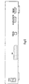
- Fig. 5 shows the front of a device designed as an ISDN-S-BOX S-BOX from Fig. 1.
- FIG. 6 shows the rear of an S-BOX device designed as an ISDN S-BOX from Fig. 1.
- the Embodiment relates to a device S-BOX, which both the function the device S-BOX from Fig. 1 as well as parts of the functions of Device SERVER from Fig. 1 takes over.
- the device S-BOX of the second embodiment is now under Using the figures 1 to 3 explained. With the same reference number Equipped facilities have the same functionality as that corresponding to the figures 1 to 3 explained.
- the S-BOX facility the first terminal END1 of the telecommunications network ISDN an intermediate memory MEMO for intermediate storage of Image information, an evaluation device AUS, which is suitable sequentially receive image information in the buffer MEMO caching and deviations and correspondences between determine two image information, and an automatic AUTO dialing device for automatically establishing a dial-up connection to a second, spatially separated from the first terminal END1 and connected to the telecommunications network ISDN terminal SERVER, the has a predetermined number, and for the transmission of a current image information together with an alarm message in case that the evaluation device AUS a deviation between the current and other image information.
- the automatic selection device AUTO is suitable for certain Times the current image information about the dial-up connection to a to transmit third terminal END2 in the event that the Evaluation device AUS a match between the current and other image information.
- the owner would like that a service provider is only informed in the event of an alarm, to take appropriate action.
- To the current status of Transferring surveillance can be the appropriate hardware and Software can be implemented in the S-BOX facility. This way and The owner becomes wise at the times determined by himself contacted directly. Concerns of the owner that he would leave as soon as he was out is continuously monitored by a "stranger", the service provider can be countered in this way.
- the S-BOX device contains a programmable control unit that is suitable to freely assign the number of the third terminal END2 program.
- the S-BOX device includes, for example, the Functionality of an ISDN video phone. The owner is therefore able to determine for yourself which phone number to which the specific Times to be transmitted for image information to be transmitted, e.g. to a videophone, e.g. at the reception of his hotel on Holiday destination.
- the S-BOX device contains a programmable control unit that is suitable to program the times at which the current Image information about the dial-up connection to the third terminal END2 should be transmitted in the event that the evaluation device AUS a Match between the current and another Image information.
- the S-BOX facility includes this for example the functionality of an ISDN videophone. The owner is thus able to determine for yourself at what times transmitting image information to be sent, for example once a day or twice a day to a videophone, e.g. at the Reception of his hotel at the vacation spot.
- the evaluation device AUS is suitable for the current image information a reference image information to compare to deviations and To find correspondences between these two image information.
- the reference image information is the same for all comparisons. This has the advantage already described above.
- the automatic selection device AUTO is suitable for certain A certain text instead of the current image information or a specific sound signal via the dial-up connection to the third End point END2 to be transmitted in the event that the evaluation device OFF a match between the current and another Image information.
- This has those already described above Advantages, e.g. Transmission to a fax machine, a (portable) computer or a mobile station.
Landscapes
- Engineering & Computer Science (AREA)
- Physics & Mathematics (AREA)
- General Physics & Mathematics (AREA)
- Multimedia (AREA)
- Library & Information Science (AREA)
- Computer Vision & Pattern Recognition (AREA)
- Computer Security & Cryptography (AREA)
- Signal Processing (AREA)
- Telephonic Communication Services (AREA)
- Monitoring And Testing Of Exchanges (AREA)
Applications Claiming Priority (2)
| Application Number | Priority Date | Filing Date | Title |
|---|---|---|---|
| DE19826087A DE19826087C2 (de) | 1998-06-12 | 1998-06-12 | Einrichtung einer Endstelle eines Telekommunikationsnetzes |
| DE19826087 | 1998-06-12 |
Publications (2)
| Publication Number | Publication Date |
|---|---|
| EP0964568A2 true EP0964568A2 (fr) | 1999-12-15 |
| EP0964568A3 EP0964568A3 (fr) | 2006-02-01 |
Family
ID=7870619
Family Applications (1)
| Application Number | Title | Priority Date | Filing Date |
|---|---|---|---|
| EP99440138A Withdrawn EP0964568A3 (fr) | 1998-06-12 | 1999-06-10 | Dispositif de surveillance et terminal d'un réseau de télécommunication associé |
Country Status (2)
| Country | Link |
|---|---|
| EP (1) | EP0964568A3 (fr) |
| DE (1) | DE19826087C2 (fr) |
Cited By (5)
| Publication number | Priority date | Publication date | Assignee | Title |
|---|---|---|---|---|
| WO2000036807A3 (fr) * | 1998-12-18 | 2000-12-21 | Cybersigns Inc | Reseau prive virtuel chiffre servant a acceder a des detecteurs a distance |
| RU2177179C1 (ru) * | 2000-06-13 | 2001-12-20 | ООО Научно-технический центр "АИР" | Система охранно-пожарной сигнализации |
| US6378072B1 (en) | 1998-02-03 | 2002-04-23 | Compaq Computer Corporation | Cryptographic system |
| RU2222051C1 (ru) * | 2002-06-21 | 2004-01-20 | Управление вневедомственной охраны при ГУВД Санкт-Петербурга и Ленинградской области | Система охранно-пожарной сигнализации |
| EP2608511A1 (fr) * | 2011-12-20 | 2013-06-26 | Telegärtner GmbH | Interphone de porte et procédé de fonctionnement d'un interphone de porte |
Family Cites Families (13)
| Publication number | Priority date | Publication date | Assignee | Title |
|---|---|---|---|---|
| DE3827928C2 (de) * | 1988-08-17 | 1997-07-10 | Sel Alcatel Ag | Bildfernsprechgerät |
| DE4203388A1 (de) * | 1992-02-06 | 1993-08-12 | Philips Patentverwaltung | Anlage zur fernueberwachung von raeumen |
| JPH05327914A (ja) * | 1992-02-18 | 1993-12-10 | Fujitsu Ltd | 割り込み機能を有するテレビ電話端末,通信切断通知機能を有するテレビ電話端末および3以上のテレビ電話端末間通信を制御するための交換機 |
| DE4229151A1 (de) * | 1992-09-01 | 1994-03-03 | Sel Alcatel Ag | Vorrichtung zur Übertragung von Videosignalen und Audiosignalen über ein diensteintegrierendes Nachrichtennetz |
| DE4402140A1 (de) * | 1994-01-26 | 1994-07-07 | Alexander Christ | Verfahren und Anlage zum Abbilden von Objekten |
| DE4407046C2 (de) * | 1994-03-03 | 2001-05-10 | Deutsche Telekom Ag | Verfahren und Anordnung zur Sicherung der Übertragung von Alarm- und Notrufdaten über ein ISDN-Netz |
| DE4408558C1 (de) * | 1994-03-14 | 1995-03-23 | Hitschfel Werner | Alarmanlage zur Überwachung von Gebäuden, Räumen, Geländeabschnitten oder Gegenständen |
| DE19512959A1 (de) * | 1995-04-10 | 1996-10-17 | Sel Alcatel Ag | Fernüberwachungsvorrichtung |
| DE19654721C1 (de) * | 1995-06-30 | 1998-05-20 | Hellemann Hans P | Verfahren zum Überwachen eines Objektes über ein digitales Datennetz |
| DE19523980C1 (de) * | 1995-06-30 | 1997-01-02 | Nca Mikroelektronic Gmbh | Verfahren zur Überwachung von Objekten über eine Datenfernübertragungsleitung |
| DE19603766A1 (de) * | 1996-02-02 | 1997-08-07 | Christian Gieselmann | Verfahren zum Erkennen gerichteter Bewegungen sowie Alarmanlage zur Durchführung des Verfahrens |
| DE19634778A1 (de) * | 1996-08-28 | 1998-03-05 | Sel Alcatel Ag | Einrichtung zur Anbindung einer Türsprechanlage mit Videokamera an ein diensteintegrierendes digitales Netz |
| AU5483998A (en) * | 1996-12-30 | 1998-07-31 | Hans-Peter Hellemann | Method for monitoring an object by means of a digital data network |
-
1998
- 1998-06-12 DE DE19826087A patent/DE19826087C2/de not_active Expired - Fee Related
-
1999
- 1999-06-10 EP EP99440138A patent/EP0964568A3/fr not_active Withdrawn
Cited By (5)
| Publication number | Priority date | Publication date | Assignee | Title |
|---|---|---|---|---|
| US6378072B1 (en) | 1998-02-03 | 2002-04-23 | Compaq Computer Corporation | Cryptographic system |
| WO2000036807A3 (fr) * | 1998-12-18 | 2000-12-21 | Cybersigns Inc | Reseau prive virtuel chiffre servant a acceder a des detecteurs a distance |
| RU2177179C1 (ru) * | 2000-06-13 | 2001-12-20 | ООО Научно-технический центр "АИР" | Система охранно-пожарной сигнализации |
| RU2222051C1 (ru) * | 2002-06-21 | 2004-01-20 | Управление вневедомственной охраны при ГУВД Санкт-Петербурга и Ленинградской области | Система охранно-пожарной сигнализации |
| EP2608511A1 (fr) * | 2011-12-20 | 2013-06-26 | Telegärtner GmbH | Interphone de porte et procédé de fonctionnement d'un interphone de porte |
Also Published As
| Publication number | Publication date |
|---|---|
| EP0964568A3 (fr) | 2006-02-01 |
| DE19826087A1 (de) | 1999-12-23 |
| DE19826087C2 (de) | 2000-08-17 |
Similar Documents
| Publication | Publication Date | Title |
|---|---|---|
| DE69727253T2 (de) | Verfahren und vorrichtung zur sychronisierten durchführung von konfigurationinformation in einem kommunikationssystem | |
| DE60300162T2 (de) | Fernüberwachungssystem und -verfahren | |
| EP0814611B1 (fr) | Méthode et système de communication pour l'enregistrement et la gestion d'images numériques | |
| DE10224788B4 (de) | Verfahren zur Beschaffung von persönlichen Notfallinformationen | |
| DE19908179A1 (de) | Überwachungsanordnung für ein Sicherheitsverbundsystem | |
| DE19509874A1 (de) | Vorrichtung und Verfahren zum Weiterleiten einer Rufinformation an einem Pager oder an ein Zweittelefon | |
| DE69531052T2 (de) | Telekommunikationsverfahren und eine zu seiner Durchführung geeignete Vorrichtung | |
| DE4420462A1 (de) | Verfahren zur Auswahl eines von mindestens zwei Fernmeldeendgeräten und Fernmeldeendgerät dafür | |
| DE19654859C1 (de) | Verfahren zur Ausgabe von Alarmierungsmeldungen und/oderProzeßdaten aus einer elektronischen Steuerung und eine Schaltungsanordnung zur Durchführung des Verfahrens | |
| EP1997277A1 (fr) | Procede et appareil pour la communication entre un grand nombre de stations mobiles et un réseau stationnaire souterrain | |
| DE19826087C2 (de) | Einrichtung einer Endstelle eines Telekommunikationsnetzes | |
| EP1574031B1 (fr) | Centre de messages multimedia et appareil de telecommunication destines a l'acces a des messages multimedia enregistres | |
| EP0828389A2 (fr) | Dispositif pour la connexion d'un système d'interphone comprenant une caméra vidéo à un réseau numérique à intégration de services | |
| DE60112297T2 (de) | Multifunktionelle vorrichtung zur entfernten signalisierung, steuerung und auslösung von ereignissen durch das telefonnetz | |
| EP1530861B1 (fr) | Procede de surveillance video d'objet au moyen d'un systeme de communication mobile | |
| DE69713405T2 (de) | Videosicherheitssystem | |
| DE102004020316B4 (de) | Türsprechanlage und Verfahren zum Betrieb einer Türsprechanlage | |
| WO2001001714A1 (fr) | Procede pour faire fonctionner un terminal mobile et un systeme radio mobile correspondant | |
| EP0879543A2 (fr) | Procede d'etablissement d'une liaison telephonique dans un reseau mobile et dispositif permettant la mise en oeuvre dudit procede | |
| DE4119555C2 (de) | Kleines Nebenstellenkommunikationssystem, insbesondere Heimtelefonsystem | |
| DE19859025C2 (de) | Funkgerät | |
| EP1668932B1 (fr) | Procédé et dispositif pour établir une liaison de communication | |
| EP0346568A2 (fr) | Méthode pour transmission de données interactive entre un central de communication et une installation de détection de présence du personnel | |
| EP1763949A1 (fr) | Procede d'interrogations a distance d'informations memorisees dans un dispositif de telecommunication, et dispositif de telecommunication a fonctionnalite d'interrogations a distance d'informations memorisees | |
| EP0673142A2 (fr) | Terminal de télécommunication |
Legal Events
| Date | Code | Title | Description |
|---|---|---|---|
| PUAI | Public reference made under article 153(3) epc to a published international application that has entered the european phase |
Free format text: ORIGINAL CODE: 0009012 |
|
| AK | Designated contracting states |
Kind code of ref document: A2 Designated state(s): AT BE CH CY DE DK ES FI FR GB GR IE IT LI LU MC NL PT SE |
|
| AX | Request for extension of the european patent |
Free format text: AL;LT;LV;MK;RO;SI |
|
| 17P | Request for examination filed |
Effective date: 20040809 |
|
| PUAL | Search report despatched |
Free format text: ORIGINAL CODE: 0009013 |
|
| AK | Designated contracting states |
Kind code of ref document: A3 Designated state(s): AT BE CH CY DE DK ES FI FR GB GR IE IT LI LU MC NL PT SE |
|
| AX | Request for extension of the european patent |
Extension state: AL LT LV MK RO SI |
|
| AKX | Designation fees paid |
Designated state(s): DE ES FR GB IT SE |
|
| RAP1 | Party data changed (applicant data changed or rights of an application transferred) |
Owner name: ALCATEL LUCENT |
|
| 17Q | First examination report despatched |
Effective date: 20070924 |
|
| STAA | Information on the status of an ep patent application or granted ep patent |
Free format text: STATUS: THE APPLICATION IS DEEMED TO BE WITHDRAWN |
|
| 18D | Application deemed to be withdrawn |
Effective date: 20080205 |