EP0964585A2 - Farbbildaufnahmegerät - Google Patents
Farbbildaufnahmegerät Download PDFInfo
- Publication number
- EP0964585A2 EP0964585A2 EP99201719A EP99201719A EP0964585A2 EP 0964585 A2 EP0964585 A2 EP 0964585A2 EP 99201719 A EP99201719 A EP 99201719A EP 99201719 A EP99201719 A EP 99201719A EP 0964585 A2 EP0964585 A2 EP 0964585A2
- Authority
- EP
- European Patent Office
- Prior art keywords
- image
- values
- value
- color
- luminance
- Prior art date
- Legal status (The legal status is an assumption and is not a legal conclusion. Google has not performed a legal analysis and makes no representation as to the accuracy of the status listed.)
- Withdrawn
Links
Images


Classifications
-
- G—PHYSICS
- G06—COMPUTING OR CALCULATING; COUNTING
- G06T—IMAGE DATA PROCESSING OR GENERATION, IN GENERAL
- G06T3/00—Geometric image transformations in the plane of the image
- G06T3/40—Scaling of whole images or parts thereof, e.g. expanding or contracting
- G06T3/4015—Image demosaicing, e.g. colour filter arrays [CFA] or Bayer patterns
-
- G—PHYSICS
- G06—COMPUTING OR CALCULATING; COUNTING
- G06T—IMAGE DATA PROCESSING OR GENERATION, IN GENERAL
- G06T3/00—Geometric image transformations in the plane of the image
- G06T3/40—Scaling of whole images or parts thereof, e.g. expanding or contracting
- G06T3/4007—Scaling of whole images or parts thereof, e.g. expanding or contracting based on interpolation, e.g. bilinear interpolation
-
- G—PHYSICS
- G06—COMPUTING OR CALCULATING; COUNTING
- G06T—IMAGE DATA PROCESSING OR GENERATION, IN GENERAL
- G06T3/00—Geometric image transformations in the plane of the image
- G06T3/40—Scaling of whole images or parts thereof, e.g. expanding or contracting
- G06T3/403—Edge-driven scaling; Edge-based scaling
-
- H—ELECTRICITY
- H04—ELECTRIC COMMUNICATION TECHNIQUE
- H04N—PICTORIAL COMMUNICATION, e.g. TELEVISION
- H04N23/00—Cameras or camera modules comprising electronic image sensors; Control thereof
- H04N23/60—Control of cameras or camera modules
- H04N23/63—Control of cameras or camera modules by using electronic viewfinders
- H04N23/633—Control of cameras or camera modules by using electronic viewfinders for displaying additional information relating to control or operation of the camera
- H04N23/634—Warning indications
-
- H—ELECTRICITY
- H04—ELECTRIC COMMUNICATION TECHNIQUE
- H04N—PICTORIAL COMMUNICATION, e.g. TELEVISION
- H04N23/00—Cameras or camera modules comprising electronic image sensors; Control thereof
- H04N23/80—Camera processing pipelines; Components thereof
- H04N23/84—Camera processing pipelines; Components thereof for processing colour signals
- H04N23/843—Demosaicing, e.g. interpolating colour pixel values
-
- H—ELECTRICITY
- H04—ELECTRIC COMMUNICATION TECHNIQUE
- H04N—PICTORIAL COMMUNICATION, e.g. TELEVISION
- H04N25/00—Circuitry of solid-state image sensors [SSIS]; Control thereof
- H04N25/10—Circuitry of solid-state image sensors [SSIS]; Control thereof for transforming different wavelengths into image signals
- H04N25/11—Arrangement of colour filter arrays [CFA]; Filter mosaics
- H04N25/13—Arrangement of colour filter arrays [CFA]; Filter mosaics characterised by the spectral characteristics of the filter elements
- H04N25/133—Arrangement of colour filter arrays [CFA]; Filter mosaics characterised by the spectral characteristics of the filter elements including elements passing panchromatic light, e.g. filters passing white light
-
- H—ELECTRICITY
- H04—ELECTRIC COMMUNICATION TECHNIQUE
- H04N—PICTORIAL COMMUNICATION, e.g. TELEVISION
- H04N25/00—Circuitry of solid-state image sensors [SSIS]; Control thereof
- H04N25/10—Circuitry of solid-state image sensors [SSIS]; Control thereof for transforming different wavelengths into image signals
- H04N25/11—Arrangement of colour filter arrays [CFA]; Filter mosaics
- H04N25/13—Arrangement of colour filter arrays [CFA]; Filter mosaics characterised by the spectral characteristics of the filter elements
- H04N25/135—Arrangement of colour filter arrays [CFA]; Filter mosaics characterised by the spectral characteristics of the filter elements based on four or more different wavelength filter elements
- H04N25/136—Arrangement of colour filter arrays [CFA]; Filter mosaics characterised by the spectral characteristics of the filter elements based on four or more different wavelength filter elements using complementary colours
-
- H—ELECTRICITY
- H04—ELECTRIC COMMUNICATION TECHNIQUE
- H04N—PICTORIAL COMMUNICATION, e.g. TELEVISION
- H04N2209/00—Details of colour television systems
- H04N2209/04—Picture signal generators
- H04N2209/041—Picture signal generators using solid-state devices
-
- H—ELECTRICITY
- H04—ELECTRIC COMMUNICATION TECHNIQUE
- H04N—PICTORIAL COMMUNICATION, e.g. TELEVISION
- H04N2209/00—Details of colour television systems
- H04N2209/04—Picture signal generators
- H04N2209/041—Picture signal generators using solid-state devices
- H04N2209/042—Picture signal generators using solid-state devices having a single pick-up sensor
- H04N2209/045—Picture signal generators using solid-state devices having a single pick-up sensor using mosaic colour filter
- H04N2209/046—Colour interpolation to calculate the missing colour values
Definitions
- This invention relates to the field of electronic imaging and is particularly suitable to electronic still imaging with improved luminance and chrominance pixel values from a measured digital image originally produced by an image sensor.
- each picture element, or pixel has three color values and can be processed by a variety of known image processing techniques depending on the needs of the system. Some examples of the reasons for processing are to do image sharpening, color correction or halftoning.
- color specification values such as, for example, luminance and chrominance values for each pixel need to be computed.
- luminance values for pixels on the edge of a feature of an image can be inaccurately interpolated.
- An object of this invention is to provide an improved apparatus which produces color specification values for pixels particularly those on the diagonal edge of a feature of the digital image.
- This object is achieved in apparatus for processing a digital color image value originally obtained from an image sensor or the like having color image pixels aligned in rows and columns having diagonal pixels with sufficient information to permit luminance estimation the digital image having at least three separate color values but only one color value for each image pixel location, such apparatus computing the luminance values for each image pixel, comprising:
- An advantage of this invention is that it is computationally efficient both in execution time and memory storage requirements for producing improved luminance or chrominance values. It is another advantage of the present invention to use the combination of the Laplacian second-order and gradient values to produce a classifier which substantially reduces artifacts (color interpolation) in output image are substantially reduced.
- the luminance and chrominance values constitute color specification for a pixel.
- portion of a color specification will refer to a pixel's luminance or chrominance values.
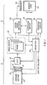
- an electronic still camera 1 is divided generally into an input section 2 and an interpolation and recording section 4.
- the input section 2 includes an exposure section 10 for directing image light from a subject (not shown) toward an image sensor 12.
- the exposure section 10 includes conventional optics for directing the image light through a diaphragm, which regulates the optical aperture, and a shutter, which regulates exposure time.
- the image sensor 12, which includes a two-dimensional array of colored photosites or pixels corresponding to picture elements of the image, can be a conventional charge-coupled device (CCD) using either well-known interline transfer or frame transfer techniques.
- the image sensor 12 is covered by a color filter array (CFA) 13.
- CFA color filter array
- the image sensor 12 is exposed to image light so that analog image charge information is generated in respective photosites.
- the charge information is applied to an output diode 14, which converts the charge information to analog image signals corresponding to respective picture elements.
- the analog image signals are applied to an A/D converter 16, which generates a digital image value from the analog input signal for each picture element.
- the digital values are applied to an image buffer 18, which may be a random access memory (RAM) with storage capacity for a plurality of still images.
- RAM random access memory
- a control processor 20 generally controls the input section 2 of the electronic still camera 1 by initiating and controlling exposure (by operation by the diaphragm and shutter (not shown) in the exposure section 10), by generating the horizontal and vertical clocks needed for driving the image sensor 12 and for clocking image information therefrom, and by enabling the A/D converter 16 in conjunction with the image buffer 18 for each value segment relating to a picture element.
- the control processor 20 typically includes a microprocessor and appropriate memory coupled to a system timing circuit. Once a certain number of digital image values have been accumulated in the image buffer 18, the stored values are applied to a digital signal processor 22, which controls the throughput processing rate for the interpolation and recording section 4 of the electronic still camera 1.
- the digital signal processor 22 applies an interpolation algorithm to the digital image values, and sends the interpolated values to a conventional, removable memory card 24 via a connector 26.
- a digital signal processor it will be understood that the digital signal processor 22 does not have to be an integral part of the electronic still camera 1.
- a requirement of this invention is that the digital image values are provided from an image sensor.
- the intermediate products of the processing algorithm are stored in a processing buffer 28.
- the processing buffer 28 may also be configured as part of the memory space of the image buffer 18.
- the number of image values needed in the image buffer 18 before digital processing can begin depends on the type of processing, that is, for a neighborhood interpolation to begin, a block of values including at least a portion of the image values comprising a video frame must be available. Consequently, in most circumstances, the interpolation may commence as soon as the requisite block of picture elements is present in the buffer 18.
- the input section 2 operates at a rate commensurate with normal operation of the electronic still camera 1 while interpolation, which may consume more time, can be relatively divorced from the input rate.
- the exposure section 10 exposes the image sensor 12 to image light for a time period dependent upon exposure requirements, for example, a time period between 1/1000 second and several seconds.
- the image charge is then swept from the photosites in the image sensor 12, convened to a digital format, and written into the image buffer 18.
- the driving signals provided by the control processor 20 to the image sensor 12, the A/D converter 16 and the buffer 18 are accordingly generated to achieve such a transfer.
- the processing throughput rate of the interpolation and recording section 4 is determined by the speed of the digital signal processor 22.
- the processing algorithm employed in the interpolation and recording section may be selected for quality treatment of the image rather than for throughput speed.
- This can put a delay between consecutive pictures which may affect the user, depending on the time between photographic events.
- This is a problem since it is well known and understood in the field of electronic imaging that a digital still camera should provide a continuous shooting capability for a successive sequence of images.
- the image buffer 18 shown in FIG. 1 provides for storage of a plurality of images, in effect allowing a series of images to "stack up" at video rates. The size of the buffer is established to hold enough consecutive images to cover most picture-taking situations.
- An operation display panel 30 is connected to the control processor 20 for displaying information useful in operation of the electronic still camera 1.
- information might include typical photographic data, such as shutter speed, aperture, exposure bias, color balance (auto, tungsten, fluorescent, daylight), field/frame, low battery, low light, exposure modes (aperture preferred, shutter preferred), and so on.
- other information unique to this type of electronic still camera 1 is displayed.
- the removable memory card 24 would ordinarily include a directory signifying the beginning and ending of each stored image. This would show on the display panel 30 as either (or both) the number of images stored or the number of image spaces remaining, or estimated to be remaining.
- the digital signal processor 22 interpolates each still video image stored in the image buffer 18 according to the interpolation technique shown in FIG. 2.
- the interpolation of missing data values at each pixel location follows the sequence shown in FIG. 2, as will later be discussed.
- the digital signal processor 22 provides an adaptive interpolation technique to provide a compute luminance function shown as luminance values block 32 for optimizing luminance values as will be described hereinafter in connection with FIG. 3A.
- a chrominance values block 34 computes the chrominance values of each pixel based upon the computed final luminance values.
- an RGB values block 36 computes the image in Red(R), Green(G), Blue(B) format which are used for an image display or for making a hard copy output.
- RGB values block 36 computes the image in Red(R), Green(G), Blue(B) format which are used for an image display or for making a hard copy output.
- RGB values block 36 computes the image in Red(R), Green(G), Blue(B) format which are used for an image display or for making a hard copy output.
- FIG. 3A where the luminance values block 32 is shown in more detail.
- a digital image from the image buffer 18 of FIG. 1 is applied to a blur block 42 which computes low frequency luminance values.
- the purpose of blur block 42 is to remove the high frequency components from the digital image.
- FIG. 4 where a 5x5 blur kernel arrangement is shown. For any given pixel which is selected as the center pixel of a 5x5 kernel it is assigned value weight of 4. Pixels which surround the kernel of interest are also assigned different values. These values shown in FIG. 4 are representative and those skilled in the art will appreciate that other values can be selected which will also provide an appropriate blur function. Note that once the weighted sum is computed is divided by 20, which is the sum of all the weights in the blur kernel. The following equations depict how these kernel values are used to compute each pixel in a digital image which has high frequency components removed.
- a pixel's horizontal and vertical classifier are both less than a fixed threshold, such as 24, the pixel is classified as "flat" and the flat predictor is used (see FIG. 7C). Otherwise, a pixel's classification is determined by the smallest classifier which indicates the preferred orientation of interpolation such as horizontal, vertical, diag1, or diag2.
- the predictors for interpolating in the preferred orientations horizontal, vertical, diag1, and diag2 are shown in FIGS. 7A, 7B, 7D, and 7E, respectively.
- the classifier values for horizontal, vertical, diag1, and diag2 were 32, 20, 18, and 25, respectively. Because the horizontal classifier 32 exceeds the threshold of 24, the pixel is not classified as "flat.” So then the minimum value 18 being the diag1 classifier determines that the preferred direction for interpolation is diag1.
- the predictor kernel weights for the diag1 direction (FIG. 7D)
- the predicted luminance value V33 would be:
- correction block 44 The operation of correction block 44 will now be discussed.
- the luminance correction term for a pixel depends on its classification and the computed blurred luminance values.
- a pixel classified as "flat" has a zero luminance correction.
- the other correction terms are determined as follows:
- the color filter array filters used are cyan (C), magenta (M), yellow (Y), and green (G).
- FIG. 3B which shows in detail the chrominance values block 34 shown in FIG. 2. Where parts correspond to FIG. 3A, the same numerals will be used.
- the color filter array data is applied to a partial block 52 which also receives luminance values as shown in FIG. 2.
- the purpose of the partial block is to provide a computation which provides chroma values that are completed by the complete block 54.
- the complete block 54 also receives an input from the classification block 48.
- each pixel location has an interpolated luminance value in addition to its original CFA color value (C, M, Y, or G).
- the pixels having Y or C can now use the interpolated luminance V in one of the above equations to compute Ca in the partial block 52.
- the pixels having M or G can use the interpolated luminance V to compute Cb in the partial block 52.
- each pixel now has an interpolated luminance value and one interpolated chrominance value. This input is applied to the complete block 54.
- the chrominance values Ca and Cb are computed on these same sub-blocks. That means that following the array shown in FIG. 8B, the known Ca and Cb values, computed in partial block 52, are arranged as follows:
- FIG. 9 which illustrates the operation of the complete block 54, the upper left 5x5 block of this array of chrominance values is shown.
- the center pixel already has an interpolated value for Cb and needs to get an interpolated value for Ca.
- Any pixel needing a value of Ca has a neighbor to the left (one or two steps away), a neighbor to the right (one or two steps away), a neighbor above (one or two steps away), a neighbor below (one or two steps away), and two neighbors touching on opposite corners (either top left and bottom right, or top right and bottom left) and all having an interpolated value for Ca.
- the two values in the horizontal direction are averaged and become the interpolated value for Ca. If the pixel was classified as vertical, then the values of Ca above and below are averaged to become the interpolated value for Ca. If the pixel was classified either as diag1 or diag2, the two values from opposite corners are averaged to become the interpolated value for Ca.
- any other pixel needing an interpolated value for Ca may be processed in a similar manner.
- each pixel needing an interpolated value for Cb may also be processed in a similar way with the roles of Ca and Cb reversed. When this step is done, every pixel has a luminance and two chrominance values, and the interpolation process is complete.
- RGB values block 36 For each pixel the conversion to red, green, and blue values (see RGB values block 36, FIG. 2) is accomplished by the following equations:
- the present invention is applicable to a digital color image value originally obtained from an image sensor or the like and has color image pixels aligned in rows and columns to define repeating kernels having diagonal pixels with sufficient information to permit luminance estimation the digital image having at least three separate color values but only one color value for each image pixel location.
- the so-called Bayer array generally takes the format shown in FIG. 8A. With this format, there is insufficient luminance (that is, green) information along certain diagonals labeled as b, d, and f of FIG. 8A. With other diagonals, there is complete information. They are labeled a, c, and e.
- the array pattern shown in US-A-5,631,703 has sufficient information (that is, magenta and green values or cyan and yellow values) along all its diagonals (for example, a-e of FIG. 8B) and so is especially suitable for use with the present invention.
- the present invention can be embodied in a computer program stored on a computer readable product such as, for example, magnetic storage media, such as a magnetic disk (for example, a floppy disk), magnetic tape, optical disks, optical tape, or machine readable memory.
- a computer readable product such as, for example, magnetic storage media, such as a magnetic disk (for example, a floppy disk), magnetic tape, optical disks, optical tape, or machine readable memory.
- apparatus for processing a digital color image value originally obtained from an image sensor or the like having color image pixels aligned in rows and columns having diagonal pixels with sufficient information to permit luminance estimation the digital image having at least three separate color values but only one color value for each image pixel location computes the luminance values for each image pixel, comprising:
- the apparatus wherein there are at least two possible selected orientations which include horizontal and vertical.
- the apparatus wherein there at least four possible selected orientations which include horizontal, vertical, and first and second diagonals.
- the apparatus further including means for selecting the smallest classifier which determines the selected orientation and corresponds to the predictor.
- apparatus for processing a measured digital color image value originally obtained from an image sensor having color image pixels aligned in rows and columns the image sensor generating at least three separate color values but only one color value for each image pixel location computes the luminance values for each image pixel, comprising:
- the apparatus further including means for using the smallest classifiers and when the horizontal and vertical classifiers are below a predetermined threshold level for selecting the flat orientation and when the smallest classifier corresponds to the horizontal, vertical, and first and second diagonals for selecting one of those orientations as the preferred orientation.
- the apparatus including means responsive to the selected orientation being flat to compute the average of the horizontal and vertical for computing a predictor which is used in determining the chrominance value for each corresponding image pixel.
- apparatus for processing a measured digital color image value originally obtained from an image sensor having color image pixels aligned in rows and columns the image sensor generating at least three separate color values but only one color value for each image pixel location computes the chrominance values for each image pixel, comprising:
- a computer program, product comprising a computer readable storage medium including program means comprising:
Landscapes
- Engineering & Computer Science (AREA)
- Physics & Mathematics (AREA)
- Multimedia (AREA)
- Signal Processing (AREA)
- General Physics & Mathematics (AREA)
- Theoretical Computer Science (AREA)
- Spectroscopy & Molecular Physics (AREA)
- Color Television Image Signal Generators (AREA)
- Image Input (AREA)
- Color Image Communication Systems (AREA)
Applications Claiming Priority (2)
| Application Number | Priority Date | Filing Date | Title |
|---|---|---|---|
| US96632 | 1998-06-12 | ||
| US09/096,632 US6075889A (en) | 1998-06-12 | 1998-06-12 | Computing color specification (luminance and chrominance) values for images |
Publications (2)
| Publication Number | Publication Date |
|---|---|
| EP0964585A2 true EP0964585A2 (de) | 1999-12-15 |
| EP0964585A3 EP0964585A3 (de) | 2000-03-29 |
Family
ID=22258311
Family Applications (1)
| Application Number | Title | Priority Date | Filing Date |
|---|---|---|---|
| EP99201719A Withdrawn EP0964585A3 (de) | 1998-06-12 | 1999-05-31 | Farbbildaufnahmegerät |
Country Status (3)
| Country | Link |
|---|---|
| US (1) | US6075889A (de) |
| EP (1) | EP0964585A3 (de) |
| JP (1) | JP2000078597A (de) |
Cited By (3)
| Publication number | Priority date | Publication date | Assignee | Title |
|---|---|---|---|---|
| EP1439715A1 (de) * | 2003-01-16 | 2004-07-21 | Dialog Semiconductor GmbH | Gewichtete gradientbasierte Farbinterpolation für eine Farbfilteranordnung |
| US7053953B2 (en) * | 2001-12-21 | 2006-05-30 | Eastman Kodak Company | Method and camera system for blurring portions of a verification image to show out of focus areas in a captured archival image |
| EP1377072A4 (de) * | 2001-03-05 | 2006-09-13 | Nikon Corp | Bildverarbeitungseinrichtung und bildverarbeitungsprogramm |
Families Citing this family (47)
| Publication number | Priority date | Publication date | Assignee | Title |
|---|---|---|---|---|
| GB2328336B (en) * | 1997-08-14 | 2001-10-10 | Quantel Ltd | An image processing system |
| US6356672B1 (en) * | 1999-03-08 | 2002-03-12 | Sharp Laboratories Of America, Inc. | Method and apparatus for reducing the color registration artifact of image capture devices |
| US6862106B1 (en) * | 1999-06-30 | 2005-03-01 | Canon Kabushiki Kaisha | Image-capturing apparatus, method of controlling the same apparatus, and computer program product for providing the same method |
| JP4317619B2 (ja) * | 1999-07-22 | 2009-08-19 | メディア・テック・ユーエスエイ・インコーポレーテッド | 画像処理装置 |
| JP4599672B2 (ja) * | 1999-12-21 | 2010-12-15 | 株式会社ニコン | 補間処理装置および補間処理プログラムを記録した記録媒体 |
| US7146042B2 (en) * | 2000-09-07 | 2006-12-05 | Nikon Corporation | Image processing apparatus and colorimetric system conversion method |
| US7088392B2 (en) * | 2001-08-27 | 2006-08-08 | Ramakrishna Kakarala | Digital image system and method for implementing an adaptive demosaicing method |
| US6862366B2 (en) * | 2001-09-13 | 2005-03-01 | Seiko Epson Corporation | Techniques for scratch and date removal from scanned film |
| US7002627B1 (en) * | 2002-06-19 | 2006-02-21 | Neomagic Corp. | Single-step conversion from RGB Bayer pattern to YUV 4:2:0 format |
| US7236191B2 (en) * | 2003-04-30 | 2007-06-26 | Nokia Corporation | Method and system for image processing with pixel interpolation using second order gradients |
| EP1641283B1 (de) | 2003-06-12 | 2019-01-09 | Nikon Corporation | Bildverarbeitungsverfahren, bildverarbeitungsprogramm, bildprozessor |
| WO2005013622A1 (ja) * | 2003-06-30 | 2005-02-10 | Nikon Corporation | 色成分の混在配列された画像を処理する画像処理装置、画像処理プログラム、電子カメラ、および画像処理方法 |
| US7463296B2 (en) * | 2004-04-01 | 2008-12-09 | Microsoft Corporation | Digital cameras with luminance correction |
| US7317843B2 (en) * | 2004-04-01 | 2008-01-08 | Microsoft Corporation | Luminance correction |
| US7852343B2 (en) * | 2004-04-15 | 2010-12-14 | Panasonic Corporation | Burst memory access method to rectangular area |
| CN100394883C (zh) * | 2005-12-02 | 2008-06-18 | 清华大学 | 无线内窥镜系统的准无损图像压缩和解压缩方法 |
| US20080123997A1 (en) * | 2006-11-29 | 2008-05-29 | Adams James E | Providing a desired resolution color image |
| US10298834B2 (en) | 2006-12-01 | 2019-05-21 | Google Llc | Video refocusing |
| US8594451B2 (en) * | 2007-03-30 | 2013-11-26 | Omnivision Technologies, Inc. | Edge mapping incorporating panchromatic pixels |
| JP4620095B2 (ja) * | 2007-08-24 | 2011-01-26 | 盛群半導體股▲ふん▼有限公司 | Ymcgカラー・フィルタ・アレイに用いられる色彩補間法 |
| TWI400961B (zh) * | 2007-08-24 | 2013-07-01 | Holtek Semiconductor Inc | 用於ymcg彩色濾波陣列的色彩內插法 |
| US7961224B2 (en) * | 2008-01-25 | 2011-06-14 | Peter N. Cheimets | Photon counting imaging system |
| US8131067B2 (en) * | 2008-09-11 | 2012-03-06 | Seiko Epson Corporation | Image processing apparatus, image processing method, and computer-readable media for attaining image processing |
| US8330827B2 (en) * | 2009-11-19 | 2012-12-11 | Eastman Kodak Company | Increasing image resolution using combined differential image |
| US9858649B2 (en) | 2015-09-30 | 2018-01-02 | Lytro, Inc. | Depth-based image blurring |
| US10334151B2 (en) | 2013-04-22 | 2019-06-25 | Google Llc | Phase detection autofocus using subaperture images |
| US9635332B2 (en) * | 2014-09-08 | 2017-04-25 | Lytro, Inc. | Saturated pixel recovery in light-field images |
| US10565734B2 (en) | 2015-04-15 | 2020-02-18 | Google Llc | Video capture, processing, calibration, computational fiber artifact removal, and light-field pipeline |
| US10275898B1 (en) | 2015-04-15 | 2019-04-30 | Google Llc | Wedge-based light-field video capture |
| US10412373B2 (en) | 2015-04-15 | 2019-09-10 | Google Llc | Image capture for virtual reality displays |
| US10546424B2 (en) | 2015-04-15 | 2020-01-28 | Google Llc | Layered content delivery for virtual and augmented reality experiences |
| US11328446B2 (en) | 2015-04-15 | 2022-05-10 | Google Llc | Combining light-field data with active depth data for depth map generation |
| US10341632B2 (en) | 2015-04-15 | 2019-07-02 | Google Llc. | Spatial random access enabled video system with a three-dimensional viewing volume |
| US10567464B2 (en) | 2015-04-15 | 2020-02-18 | Google Llc | Video compression with adaptive view-dependent lighting removal |
| US10444931B2 (en) | 2017-05-09 | 2019-10-15 | Google Llc | Vantage generation and interactive playback |
| US10440407B2 (en) | 2017-05-09 | 2019-10-08 | Google Llc | Adaptive control for immersive experience delivery |
| US10419737B2 (en) | 2015-04-15 | 2019-09-17 | Google Llc | Data structures and delivery methods for expediting virtual reality playback |
| US10540818B2 (en) | 2015-04-15 | 2020-01-21 | Google Llc | Stereo image generation and interactive playback |
| US10469873B2 (en) | 2015-04-15 | 2019-11-05 | Google Llc | Encoding and decoding virtual reality video |
| US9979909B2 (en) | 2015-07-24 | 2018-05-22 | Lytro, Inc. | Automatic lens flare detection and correction for light-field images |
| US10275892B2 (en) | 2016-06-09 | 2019-04-30 | Google Llc | Multi-view scene segmentation and propagation |
| US10679361B2 (en) | 2016-12-05 | 2020-06-09 | Google Llc | Multi-view rotoscope contour propagation |
| US10594945B2 (en) | 2017-04-03 | 2020-03-17 | Google Llc | Generating dolly zoom effect using light field image data |
| US10474227B2 (en) | 2017-05-09 | 2019-11-12 | Google Llc | Generation of virtual reality with 6 degrees of freedom from limited viewer data |
| US10354399B2 (en) | 2017-05-25 | 2019-07-16 | Google Llc | Multi-view back-projection to a light-field |
| US10545215B2 (en) | 2017-09-13 | 2020-01-28 | Google Llc | 4D camera tracking and optical stabilization |
| US10965862B2 (en) | 2018-01-18 | 2021-03-30 | Google Llc | Multi-camera navigation interface |
Citations (1)
| Publication number | Priority date | Publication date | Assignee | Title |
|---|---|---|---|---|
| US5631703A (en) * | 1996-05-29 | 1997-05-20 | Eastman Kodak Company | Particular pattern of pixels for a color filter array which is used to derive luminance and chrominance values |
Family Cites Families (6)
| Publication number | Priority date | Publication date | Assignee | Title |
|---|---|---|---|---|
| US3971065A (en) * | 1975-03-05 | 1976-07-20 | Eastman Kodak Company | Color imaging array |
| US5629734A (en) * | 1995-03-17 | 1997-05-13 | Eastman Kodak Company | Adaptive color plan interpolation in single sensor color electronic camera |
| US5506619A (en) * | 1995-03-17 | 1996-04-09 | Eastman Kodak Company | Adaptive color plan interpolation in single sensor color electronic camera |
| US5596367A (en) * | 1996-02-23 | 1997-01-21 | Eastman Kodak Company | Averaging green values for green photosites in electronic cameras |
| US5652621A (en) * | 1996-02-23 | 1997-07-29 | Eastman Kodak Company | Adaptive color plane interpolation in single sensor color electronic camera |
| JP3031613B2 (ja) * | 1996-11-12 | 2000-04-10 | 株式会社つくばソフト研究所 | カラー/濃淡画像入力出力装置と入力出力方法 |
-
1998
- 1998-06-12 US US09/096,632 patent/US6075889A/en not_active Expired - Lifetime
-
1999
- 1999-05-31 EP EP99201719A patent/EP0964585A3/de not_active Withdrawn
- 1999-06-11 JP JP11165172A patent/JP2000078597A/ja active Pending
Patent Citations (1)
| Publication number | Priority date | Publication date | Assignee | Title |
|---|---|---|---|---|
| US5631703A (en) * | 1996-05-29 | 1997-05-20 | Eastman Kodak Company | Particular pattern of pixels for a color filter array which is used to derive luminance and chrominance values |
Cited By (6)
| Publication number | Priority date | Publication date | Assignee | Title |
|---|---|---|---|---|
| EP1377072A4 (de) * | 2001-03-05 | 2006-09-13 | Nikon Corp | Bildverarbeitungseinrichtung und bildverarbeitungsprogramm |
| US7289665B2 (en) | 2001-03-05 | 2007-10-30 | Nikon Corporation | Image processing device and image processing program |
| EP2056607A1 (de) * | 2001-03-05 | 2009-05-06 | Nikon Corporation | Bildverarbeitungseinrichtung und Bildverarbeitungsprogramm |
| US7053953B2 (en) * | 2001-12-21 | 2006-05-30 | Eastman Kodak Company | Method and camera system for blurring portions of a verification image to show out of focus areas in a captured archival image |
| EP1439715A1 (de) * | 2003-01-16 | 2004-07-21 | Dialog Semiconductor GmbH | Gewichtete gradientbasierte Farbinterpolation für eine Farbfilteranordnung |
| US7256828B2 (en) | 2003-01-16 | 2007-08-14 | Dialog Imaging Systems Gmbh | Weighted gradient based and color corrected interpolation |
Also Published As
| Publication number | Publication date |
|---|---|
| US6075889A (en) | 2000-06-13 |
| EP0964585A3 (de) | 2000-03-29 |
| JP2000078597A (ja) | 2000-03-14 |
Similar Documents
| Publication | Publication Date | Title |
|---|---|---|
| US6075889A (en) | Computing color specification (luminance and chrominance) values for images | |
| EP0732859B1 (de) | Adaptive Farbebeneninterpolation in einer elektronischen Einfachsensorfarbkamera | |
| US5596367A (en) | Averaging green values for green photosites in electronic cameras | |
| US5652621A (en) | Adaptive color plane interpolation in single sensor color electronic camera | |
| EP0732858B1 (de) | Adaptive Interpolation von Farbflächen in einer elektronischen Farbkamera mit nur einem Sensor | |
| US5382976A (en) | Apparatus and method for adaptively interpolating a full color image utilizing luminance gradients | |
| US6697107B1 (en) | Smoothing a digital color image using luminance values | |
| US5373322A (en) | Apparatus and method for adaptively interpolating a full color image utilizing chrominance gradients | |
| US6192162B1 (en) | Edge enhancing colored digital images | |
| US5808674A (en) | Producing and improved digital image from digital signals corresponding to pairs of photosites | |
| JP5108172B2 (ja) | 画像データサイズ変換処理装置、電子スチルカメラ、および画像データサイズ変換処理用記録媒体 | |
| US7808533B2 (en) | Electronic camera having signal processing units that perform signal processing on image data | |
| US6900836B2 (en) | Correcting defects in a digital image caused by a pre-existing defect in a pixel of an image sensor | |
| US7148925B2 (en) | Solid-state honeycomb type image pickup apparatus using a complementary color filter and signal processing method therefor | |
| US7586525B2 (en) | Noise reduction apparatus, method and program | |
| US6897425B2 (en) | Method of processing an image signal with the result from decision on a correlation corrected | |
| US6542187B1 (en) | Correcting for chrominance interpolation artifacts | |
| US6809765B1 (en) | Demosaicing for digital imaging device using perceptually uniform color space | |
| JP2002010276A (ja) | 撮像装置 | |
| US6034724A (en) | Imaging device utilizing a line-crawling correction coefficient | |
| JPH07123421A (ja) | 撮像装置 | |
| US7564490B2 (en) | Noise reduction apparatus, method and program | |
| JP2002209100A (ja) | 画像処理装置および画像処理方法 | |
| JP3962518B2 (ja) | 画像信号処理装置 | |
| JP2002209224A (ja) | 画像処理装置、画像処理方法および記録媒体 |
Legal Events
| Date | Code | Title | Description |
|---|---|---|---|
| PUAI | Public reference made under article 153(3) epc to a published international application that has entered the european phase |
Free format text: ORIGINAL CODE: 0009012 |
|
| AK | Designated contracting states |
Kind code of ref document: A2 Designated state(s): DE FR GB |
|
| AX | Request for extension of the european patent |
Free format text: AL;LT;LV;MK;RO;SI |
|
| PUAL | Search report despatched |
Free format text: ORIGINAL CODE: 0009013 |
|
| AK | Designated contracting states |
Kind code of ref document: A3 Designated state(s): AT BE CH CY DE DK ES FI FR GB GR IE IT LI LU MC NL PT SE |
|
| AX | Request for extension of the european patent |
Free format text: AL;LT;LV;MK;RO;SI |
|
| 17P | Request for examination filed |
Effective date: 20000902 |
|
| AKX | Designation fees paid |
Free format text: DE FR GB |
|
| 17Q | First examination report despatched |
Effective date: 20070921 |
|
| STAA | Information on the status of an ep patent application or granted ep patent |
Free format text: STATUS: THE APPLICATION IS DEEMED TO BE WITHDRAWN |
|
| 18D | Application deemed to be withdrawn |
Effective date: 20091030 |