EP0964643B1 - Tomodensitometre helicoidal a axe de scintigraphie a orientation variable - Google Patents
Tomodensitometre helicoidal a axe de scintigraphie a orientation variable Download PDFInfo
- Publication number
- EP0964643B1 EP0964643B1 EP97904563A EP97904563A EP0964643B1 EP 0964643 B1 EP0964643 B1 EP 0964643B1 EP 97904563 A EP97904563 A EP 97904563A EP 97904563 A EP97904563 A EP 97904563A EP 0964643 B1 EP0964643 B1 EP 0964643B1
- Authority
- EP
- European Patent Office
- Prior art keywords
- view
- axis
- row
- elements
- detector elements
- Prior art date
- Legal status (The legal status is an assumption and is not a legal conclusion. Google has not performed a legal analysis and makes no representation as to the accuracy of the status listed.)
- Expired - Lifetime
Links
- 238000001514 detection method Methods 0.000 claims description 20
- 230000001154 acute effect Effects 0.000 claims description 5
- 238000000034 method Methods 0.000 description 12
- 239000011159 matrix material Substances 0.000 description 11
- 230000001419 dependent effect Effects 0.000 description 7
- 238000013170 computed tomography imaging Methods 0.000 description 4
- 238000003491 array Methods 0.000 description 3
- 238000001914 filtration Methods 0.000 description 2
- 230000005855 radiation Effects 0.000 description 2
- 238000006073 displacement reaction Methods 0.000 description 1
- 238000003384 imaging method Methods 0.000 description 1
- 238000010606 normalization Methods 0.000 description 1
- 210000000496 pancreas Anatomy 0.000 description 1
- 239000007787 solid Substances 0.000 description 1
Images


Classifications
-
- A—HUMAN NECESSITIES
- A61—MEDICAL OR VETERINARY SCIENCE; HYGIENE
- A61B—DIAGNOSIS; SURGERY; IDENTIFICATION
- A61B6/00—Apparatus or devices for radiation diagnosis; Apparatus or devices for radiation diagnosis combined with radiation therapy equipment
- A61B6/02—Arrangements for diagnosis sequentially in different planes; Stereoscopic radiation diagnosis
- A61B6/03—Computed tomography [CT]
- A61B6/032—Transmission computed tomography [CT]
-
- A—HUMAN NECESSITIES
- A61—MEDICAL OR VETERINARY SCIENCE; HYGIENE
- A61B—DIAGNOSIS; SURGERY; IDENTIFICATION
- A61B6/00—Apparatus or devices for radiation diagnosis; Apparatus or devices for radiation diagnosis combined with radiation therapy equipment
- A61B6/02—Arrangements for diagnosis sequentially in different planes; Stereoscopic radiation diagnosis
- A61B6/027—Arrangements for diagnosis sequentially in different planes; Stereoscopic radiation diagnosis characterised by the use of a particular data acquisition trajectory, e.g. helical or spiral
-
- Y—GENERAL TAGGING OF NEW TECHNOLOGICAL DEVELOPMENTS; GENERAL TAGGING OF CROSS-SECTIONAL TECHNOLOGIES SPANNING OVER SEVERAL SECTIONS OF THE IPC; TECHNICAL SUBJECTS COVERED BY FORMER USPC CROSS-REFERENCE ART COLLECTIONS [XRACs] AND DIGESTS
- Y10—TECHNICAL SUBJECTS COVERED BY FORMER USPC
- Y10S—TECHNICAL SUBJECTS COVERED BY FORMER USPC CROSS-REFERENCE ART COLLECTIONS [XRACs] AND DIGESTS
- Y10S378/00—X-ray or gamma ray systems or devices
- Y10S378/901—Computer tomography program or processor
Definitions
- the present invention relates generally to computerized tomographic (CT) imaging, and specifically to multi-slice CT scanners having helical scan paths.
- CT computerized tomographic
- Helical-path CT scanners are well known in the art.
- such scanners comprise an X-ray tube, mounted on an annular gantry, so as to rotate continuously about a subject being imaged.
- the subject lies on a table, which is translated continuously through the gantry simultaneously with the gantry's rotation, while X-ray detectors on the opposite side of the subject from the X-ray tube receive radiation transmitted through the subject.
- the axis of translation of the bed is generally parallel to the long axis of the subject's body, which is typically perpendicular to the plane of rotation of the gantry.
- the path of the X-ray tube relative to the subject generally describes a helix about this axis, and X-ray attenuation data received from the X-ray detectors similarly correspond to a series of helically-disposed "views" through the subject.
- attenuation data for each point in such a planar slice are derived by interpolation between data points in the original helical-path views.
- Document EP-A-0 471 455 discloses a helical CT apparatus comprising means for producing a planar corrected view by interpolation of data from first and second views having the same effective view angle, means repeating these steps at a plurality of rotational angles of the X-ray tube, and means for reconstructing a planar image slice from corrected views taken over said plurality of view angles.
- Multi-slice helical-path scanners are similarly known in the art.
- U.S. patent 5,485,493 describes a multiple detector ring spiral scanner with relatively adjustable helical paths, in which two or more adjacent, parallel slices are acquired along two or more parallel paths simultaneously or sequentially. Data corresponding to planar slices are derived by interpolating between data acquired along the two helical paths.
- Helical-path scanners in which more than two slices are acquired are also known in the art.
- the long axis of the subject's body, along which direction the bed is translated may be angled relative to the plane of rotation of the gantry, rather than being perpendicular to the axis, as in conventional scanners.
- This angling typically includes swiveling the bed about a vertical axis, tilting the gantry about a horizontal axis, or a combination of swiveling and tilting. Since the image views are similarly angled relative to the body axis, this angling function is frequently useful in resolving image features that may be difficult to observe in conventional, non-angled scanning.
- bed swivel may be used in generating longitudinal image slices through the pancreas
- variable gantry tilt may be used to generate images of angled, sectional cuts through the disc spaces of the spine.
- the object is solved by an apparatus according to the invention as defined in claim 1.
- angled helical scan data generated during different positions of the gantry are combined to form a data set of a view for reconstruction of the image.
- the helical-scan data are used to reconstruct planar corrected image slices.
- the CT data comprise multiple-slice CT data, acquired using a multi-row detector array.
- a variable-angle multi-slice helical-scan CT scanner comprises an X-ray tube, mounted on an annular gantry, which rotates about a bed on which a subject lies, and a detector array.
- the X-ray tube irradiates the subject from multiple points along its helical trajectory.
- the detector array comprises one or more parallel rows of X-ray detector elements, each row having a long axis disposed in a generally circumferential direction with respect to the long axis of the subject's body.
- the detector elements receive radiation that has passed through the subject's body and generate signals responsive to attenuation of the X-rays.
- the bed is advanced through the gantry along a translation axis that is generally parallel to the long axis of the subject's body.
- the gantry tilts about a horizontal axis, and the bed swivels, relative to the gantry, about a vertical axis, so that the translation axis of the bed describes an acute angle relative to the axis of rotation of the gantry.
- the scanner thus performs an angled helical scan over at least a portion of the body.
- the detector array For each view, i.e., each position of the X-ray tube relative to the body at which X-ray attenuation signals are received from the detector array, the detector array generates a matrix of attenuation signals. Each row in the signal matrix corresponds to a row of elements in the detector array. These signals are normalized and undergo a log operation, as is known in the art.
- the resultant data are then interpolated to generate geometrically-corrected CT data, which are associated with planar slices through the body. These slices are generally perpendicular to the gantry rotation axis, and are therefore swiveled and/or tilted with respect to the long axis of the body.
- the corrected data in these planar slices are filtered and back-projected to reconstruct a three-dimensional CT image of the subject's body, using methods known in the art.
- the "raw" signals may first be interpolated before undergoing the log operations.
- the data may be interpolated after the filtering or after the back-projection operation. It will be appreciated that the principles of the present invention may be applied in these cases, as well.
- the geometrically-corrected CT data comprise effective attenuation values with respect to each of the planar slices. For each slice, these values are calculated for a plurality of effective detection points, geometrically fixed along a periphery of the slice. Each of the effective attenuation values corresponds to the approximate attenuation that would have been measured along a ray in the planar slice from the X-ray tube to the location of the effective detection point, at a given rotation angle of the tube about the gantry's axis of rotation.
- the effective attenuation values for each planar slice are calculated for a plurality of rotation angles, preferably covering 360° of rotation about the axis (or more, depending on the helix angle). These values are filtered and back-projected using 360° CT image reconstruction, as is known in the art. Reconstruction using single slices requires at least two rotations and generally more, depending on the helix angle.
- the effective detection points are fixed in the plane of the slice, the actual elements of the detector array are generally not in this plane.
- the positions of the actual elements relative to the effective detection points vary from one tube rotation angle to another, due to the helical shape of the scan path. Therefore, for each of the effective detection points at each rotation angle, two or more detector elements are selected.
- the elements selected are those whose positions are geometrically closest to the position of the effective detection point at that rotation angle.
- the actual, measured attenuation data at the element positions are interpolated to calculate the corresponding effective attenuation value at the effective detection point.
- the actual elements selected for some rotation angles will be mutually-adjacent elements in adjoining, parallel rows of the array.
- the effective attenuation values are interpolated from measured attenuation data from adjacent rows of the signal matrix at a single view, i.e., signals that are acquired while the X-ray tube is at one, given position along the helical scan path.
- the effective attenuation values are interpolated from two or more different signal matrix rows, acquired at different views of the X-ray tube along the helical scan path.
- the different views are separated by a 360° rotation of the gantry, which is accompanied by translational motion of the bed through the gantry. Additional data may be acquired during further rotations.
- the actual detector elements whose positions are closest to any one of the effective detection points are typically not mutually adjacent elements of the array.
- the tilt and/or swivel of the scanner introduces an offset, dependent on the rotation angle, between the positions of the elements.
- the actual detector elements corresponding to each effective detection point are selected based on the tilt and/or swivel angles, the rotation angle, the pitch of the helical path, and other geometrical considerations. Failure to take any of these aspects into account will typically result in artifacts appearing in the CT image.
- each effective attenuation value, for each effective detection point is calculated by weighted interpolation between actual attenuation values derived from two different signal matrix rows. Weighting factors for the interpolation at each point are preferably determined based on the respective distances between the point and the positions of the corresponding actual detector elements. Most preferably, the element closest to the point has the largest weighting factor.
- the effective attenuation values are calculated by weighted interpolation between elements in three or more different signal matrix rows.
- the wider range of interpolation is useful in reducing noise and artifacts in the resultant image.
- the weighting factors are preferably dependent on the distances between each of the effective detection points and the corresponding actual detector elements, as described above.
- an apparatus for reconstructing images of a subject in a variable-angle helical-scan CT scanner includes an X-ray tube mounted for rotation about a rotation axis, a detector array having one or more rows of detector elements that generate signals responsive to X-rays incident thereon, and a bed, translatable along a translation axis, on which bed the subject is placed, said apparatus being adapted for: angling the translation axis and the rotation axis at an acute angle relative to one another; rotating the X-ray tube about the rotation axis while translating the bed along the translation axis through a plane of rotation of the tube, whereby the X-ray tube describes a helical path relative to the subject; acquiring first and second views of the subject at the same effective rotational angle about the axis of rotation, said views comprising X-ray attenuation data received from elements of the array; producing a planar corrected image slice by interpolation of the data in different views, according to the way the way the way the apparatus is adapted for:
- producing the planar corrected image slice comprises:
- finding first and second rows of detector elements comprises finding two adjoining rows of the detector array in one of the first and second views.
- finding first and second rows of detector elements comprises finding a first row in the first view and a second row in the second view, and wherein determining first and second attenuation values comprises determining an offset between the first and second rows.
- determining the offset between the first and second rows comprises determining an offset dependent on the rotational angle of the X-ray tube.
- determining the offset between the first and second rows comprises determining an offset dependent on the acute angle between the translation axis and the rotation axis.
- determining the first attenuation value comprises computing a weighted sum of attenuation data received from two or more detector elements in the first row.
- determining the second attenuation value comprises computing a weighted sum of attenuation data received from two or more detector elements in the second row.
- calculating the effective attenuation value by weighted interpolation comprises determining weighting factors dependent on the rotational angle of the X-ray tube.
- calculating the effective attenuation value by weighted interpolation preferably comprises determining weighting factors dependent on the acute angle between the translation axis and the rotation axis.
- determining the first attenuation value at a point in the view comprises finding the two elements in the first row whose centroids are closest to the point and calculating an effective row element attenuation value based on signals received from the two elements.
- determining the second attenuation value at a point in the view preferably comprises finding the two elements in the second row whose centroids are closest to the point and calculating an effective row element attenuation value based on signals received from the two elements.
- the apparatus is furthermore adapted for finding one or more additional rows of detector elements, parallel to the first and second rows, and determining one or more additional attenuation values from the additional rows, wherein calculating an effective attenuation value in the planar slice comprises calculating the effective attenuation value by weighted interpolation of the additional values with the first and second attenuation values.
- the apparatus is furthermore adapted for acquiring one or more additional views at the same effective rotational angle as the first and second views, wherein producing the planar corrected image slice by interpolation of the data in the views comprises combining the one or more additional views with the first and second views by weighted interpolation of the data.
- the detector array has one row of elements. In an alternative preferred embodiment of the invention, the detector array has more than one row of elements.
- Scanner 20 comprises a bed 24, supported by a base 26, on which bed a subject 22 lies while his body is being imaged by the scanner.
- Scanner 20 further comprises an X-ray tube 28, which irradiates subject 22, and a detector array 30, which receives X-rays from tube 28 and generates signals responsive to the attenuation of the X-rays in passing through the subject's body.
- array 30 comprises multiple, parallel rows of X-ray detector elements 23.
- Tube 28 and array 30 are mounted on an annular gantry 32, so as to rotate about subject 22. Simultaneously, bed 24 is advanced through gantry 32 along axis 34, which is generally parallel to the long axis of the subject's body.
- Scanner 20 as pictured in Fig. 1 is of a type known in the art as a third-generation CT-scanner, characterized in that both tube 28 and detector array 30 rotate about subject 22. It will be appreciated, however, that the principles of the present invention and the methods of image reconstruction to be described below are equally applicable to other types of CT scanners, for example, fourth-generation CT scanners, which include annular detector arrays that are generally rotationally stationary, while the X-ray tube rotates about the subject.
- Scanner 20 may be configured so that axis 34 is substantially perpendicular to the plane of rotation of gantry 32. Additionally, axis 34 may preferably be angled relative to the gantry plane, for example, by swiveling bed 24 horizontally, in a direction indicated by arrow 33, and/or by tilting gantry 32 about a generally horizontal tilt axis in a direction indicated by arrow 35. Preferably, the tilt and swivel angles are controlled by a system control unit 46, which also regulates the rotation of the gantry and the advance of the bed.
- Fig. 1 rotating, gantry-fixed axes X, Y, Z, indicated by dashed arrows, and bed-fixed axes X', Y', Z', indicated by solid arrows.
- the Z-axis is substantially the axis of rotation of gantry 32 and is fixed in space.
- the Y-axis points from the center of rotation of the gantry to tube 28 and rotates therewith, and the X-axis is, therefore, generally parallel to the long axis of array 30.
- the Z'-axis is parallel to bed axis 34.
- Axis Y' points vertically upward, parallel to the swivel axis (if any) of bed 24, and axis X' is thus generally horizontal.
- Axis Z' is angled relative to axis Z by a two-dimensional angle ⁇ , which takes into account both the tilt of gantry 32 and the swivel of bed 24. The angle of rotation of the gantry ⁇ is taken to be zero when tube 28 is at its uppermost rotational position.
- the tube As tube 28 rotates and bed 24 advances, the tube describes a generally spiral path around axis 34. Preferably, bed 24 moves with substantially constant velocity, so that the spiral path has a constant pitch.
- data acquisition circuitry 36 acquires a matrix of attenuation signals.
- the elements of this matrix are signals received from each detector element 23 of array 30 responsive to X-ray attenuation along a ray from tube 28 to the detector element.
- Each such matrix may comprise a plurality of rows, wherein each such row corresponds to signals received at one of the plurality of views from one of the multiple rows of array 30.
- data acquisition circuitry 36 For each view, data acquisition circuitry 36 performs signal normalization and logarithm operations, as are known in the art, to derive an X-ray attenuation value corresponding to each of elements 23.
- Image reconstruction circuitry 40 receives these values and performs interpolation and other data processing operations, as will be described below, to convert the views acquired during the helical scan into corrected, planar image slices at desired positions along the Z-axis. These planar image slices may then be used to reconstruct three-dimensional or other CT images of the body of subject 22, using methods known in the art.
- these images are stored in image memory 42, displayed by display unit 44, and may be otherwise printed and/or processed as is known in the art.
- the data and/or images may also be stored for later reconstruction and or display.
- Fig. 2A schematically represents the positions and detection areas of detector elements 23 in array 30 in two views, labeled "VIEW 1" and "VIEW 2."
- two views will be said to be acquired at the same effective rotational angle when they are acquired at gantry positions separated by an integer number of full, 360° rotations, for the case of 360° reconstruction.
- array 30 is shown as having only two parallel rows 27 and 29 of detectors 23, each row comprising M detector elements 23, labeled D 11 ..D 1M and D 21 ..D 2M respectively.
- Gantry 32 is assumed to be tilted by angle ⁇ relative to bed 24, while the swivel angle of bed 24 is substantially zero. It will be understood, however, that the principles of the method to be described below are equally applicable to multi-slice arrays having greater or lesser numbers of rows, and to configurations of scanner 20 in which bed 24 has a non-zero swivel angle. Similarly, the method applies generally for any rotational angle ⁇ of tube 28, as will be shown below.
- a planar image slice is to be reconstructed in a plane parallel to the rotation plane of gantry 32, at the position marked Z 0 .
- FIG. 2A there is no view acquired that includes a row 27 or 29 centered at Z 0 .
- a corrected slice at this position is reconstructed by choosing and interpolating between a plurality of effective detection points around a periphery of the corrected slice, at a radial distance from the Z-axis that is generally equal to the distance of the detection points in rows 27 and 29 of array 30 from the Z axis.
- An effective attenuation value is determined at each of the points by interpolating between the X-ray attenuation data received from two or more elements 23 in different rows 27 and 29 and/or in different views, VIEW 1 and VIEW 2.
- the effective attenuation at each of the plurality of points corresponds, in close approximation, to the attenuation that would be measured along a line in the X-Y plane from X-ray tube 28 to the point.
- a weighted sum is taken of data input from element D 2i in VIEW 1 and data input from its adjacent element D 1i in VIEW 2.
- the weighting factors for the two input elements will vary inversely with the relative distances of the respective centroids of the two elements from point 50. These weighting factors will generally be the same, however, for all points (at varying values of R) along the periphery of the slice at position Z 0 . If the fan beam data is rebinned into parallel beam data an adjustment of the weighting for different positions on the fan may be desirable. However, such adjustments generally quite small.
- greater numbers of input elements may be included in the weighted sum to determine the effective attenuation value at point 50, so as to improve the quality of the image, using Z-axis weighting or filtering methods known in the art.
- the attenuation data from array 30 may be reformatted, as is known in the art, from the fan beam format in which the attenuation signals are received, as exemplified in Fig. 1, to a parallel beam format, for the purpose of improving the quality of the resultant CT image. It will be understood that the methods described herein with reference to elements 23 and the unreforrnatted data received are preferably applied to such reformatted data samples.
- point 50 at position Z 0 is shown in Fig. 2A as being midway between rows 27 and 29, it will be understood that the method described above may be applied to determine effective attenuation values at any Z-position in between rows 27 and 29 or within the detection area of one of the rows.
- the effective attenuation value at the point is preferably derived directly from the attenuation data in that row.
- the effective attenuation value may be calculated by taking a weighted average of the data in the row within which point 50 is centered with data from neighboring rows on either side thereof.
- Fig. 2B schematically represents the positions of detector elements 23 in the same configuration of scanner 20 as in Fig. 2A, i.e., with tilt angle ⁇ .
- the Z-axis of gantry 32 is seen to be tilted with respect to the Z'-axis of bed 24, and the positions of elements 23 of array 30 in the two views are mutually offset along the X-axis.
- bed 24 has advanced along the Z'-axis direction relative to its position in VIEW 1 and VIEW 2, the X-axis, coinciding with the plane of the image to be reconstructed, is shown in Fig. 2B as having shifted in the Z'-direction.
- elements 23 of array 30 are taken to have a common pitch P.
- Each of the two rows 27 and 29 of array 30 has a respective longitudinal axis passing substantially through the centroids of the elements in the row, which axes are marked 52a and 54a respectively for VIEW 1', and 52b and 54b respectively for VIEW 2'.
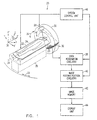
- Fig. 3 is a flow chart illustrating a method for calculating effective attenuation values in a planar image slice in the X-Y plane, generally perpendicular to the rotation axis of gantry 32, in accordance with a preferred embodiment of the present invention.
- the key steps in this method involve taking a plurality of effective detection points in the periphery of the plane, as described above, and then selecting and calculating appropriate input data from elements 23 to determine the effective attenuation values at each of the plurality of points.
- the process of selecting and calculating the effective attenuation values is repeated at each of a plurality of gantry rotation angles ⁇ .
- at least two attenuation signal matrices from respective views at angles ⁇ and ⁇ +360°, are used in the calculation.
- image reconstruction circuitry 40 receives the coordinates of rows 27 and 29 in VIEW 1' and VIEW 2' from system control unit 46 (shown in Fig. 1). The circuitry compares the Z-axis position of the plane for reconstruction, marked by the X-axis, with the positions of rows 27 and 29 to determine which of axes 52a, 54a, 52b and 54b is closest to the plane. In the case shown in Fig. 2B, axis 52b in VIEW 2' is the closest. If two axes are equidistant from the plane, then either may be chosen as the closest, and the remainder of the calculation is substantially unaffected.
- the circuitry determines which of the remaining row axes is the next closest to the point. For some rotation angles ⁇ , the next closest axis is from the same view as the closest axis. Such would be the case, for example, with regard to a plane passing through point 56 in Fig. 2B, for which axis 54b is the next closest.
- the corrected attenuation value at point 56 is then determined simply by weighted interpolation between elements D 1,k and D 2,k , with the weighting factors dependent on the relative distances of axes 52b and 54b from point 56.
- Element D 2,k+2 in VIEW 1' is closest to point 55 in its detection area, but the border between this element and its neighboring element in array 30, D 2,k+1 , is offset relative to the borders between element D 1,k and its neighboring elements in VIEW 2'.
- an effective row element attenuation value is calculated by weighted interpolation between the attenuation values of elements D 2,k+1 and D 2,k+2 in VIEW 1'.
- Weighting factors for this interpolation are calculated based on the relative offset of elements 23 of array 30 between VIEW 1' and VIEW 2'. This effective row element attenuation value is then combined by weighted interpolation with the value of the first input element (in this case D 1,k in VIEW 2') to compute the effective attenuation value at point 55.
- V eff V 2,k for M-1- ⁇ Z' ⁇ sin ⁇ /P ⁇ k ⁇ M-1
- V eff W m V 2,m + W m+1 V 2,m+1 for 0 ⁇ k ⁇ M-1- ⁇ Z' ⁇ sin ⁇ /P
- m INT[k + ⁇ Z' ⁇ sin ⁇ /P]
- W m and W m+1 are interpolation weighting factors
- INT(x) is the greatest integer in x.
- ⁇ ⁇ , where ⁇ is the tilt angle of bed 24
- weighting factors may similarly be used, such as, but not limited to utilizing more elements per row, depending, inter alia , on geometrical considerations in the CT scanner.
- effective row attenuation values are calculated for the row whose axis is nearest the plane of the planar corrected slice, as well as for the row whose axis is next-nearest the plane.
- an effective row attenuation value for row 27 could be calculated with respect to point 55 by weighted interpolation between elements D 1,k and D 1,k-1 in VIEW 2'. The value would then be combined by weighted interpolation with the value of V eff determined for row 29 in VIEW 1', as described above, to calculate the effective attenuation value for point 55.
- data from more than two rows may be combined by interpolation to determine effective attenuation values for a planar corrected slice.
- the respective offset of each of the rows is taken into account, and interpolative weighting factors are calculated accordingly, based on the principles described above.
Landscapes
- Health & Medical Sciences (AREA)
- Life Sciences & Earth Sciences (AREA)
- Engineering & Computer Science (AREA)
- Medical Informatics (AREA)
- Radiology & Medical Imaging (AREA)
- Molecular Biology (AREA)
- Biophysics (AREA)
- Nuclear Medicine, Radiotherapy & Molecular Imaging (AREA)
- Optics & Photonics (AREA)
- Pathology (AREA)
- Physics & Mathematics (AREA)
- Biomedical Technology (AREA)
- Heart & Thoracic Surgery (AREA)
- High Energy & Nuclear Physics (AREA)
- Surgery (AREA)
- Animal Behavior & Ethology (AREA)
- General Health & Medical Sciences (AREA)
- Public Health (AREA)
- Veterinary Medicine (AREA)
- Pulmonology (AREA)
- Theoretical Computer Science (AREA)
- Apparatus For Radiation Diagnosis (AREA)
Claims (3)
- Appareil pour reconstruire des images d'un sujet, comprenant:dans lequel l'axe de translation (Z') et l'axe de rotation (Z) forment un angle aigu () l'un par rapport à l'autre;un scanner CT à balayage hélicoïdal à angle variable, ledit scanner comprenant:un tube à rayons X (28) monté de manière à tourner autour d'un axe de - rotation (Z);un ensemble de détecteurs (30) comportant une ou plusieurs rangées d'éléments détecteurs (23), comportant chacun une zone de détection, qui génèrent des signaux en fonction des rayons X qui les frappent, chaque rangée comprenant M éléments détecteurs, M étant un nombre entier, et les éléments détecteurs dans chaque rangée étant marqués par un indice k, k étant 1 ≤ k ≤ M; etun lit (24), déplaçable le long d'un axe de translation (Z'), le sujet (22) étant placé sur le lit,un moyen pour faire tourner le tube à rayons X autour de l'axe de rotation (Z) tout en déplaçant le lit (24) le long de l'axe de translation (Z') à travers un plan de rotation du tube (28), de sorte que le tube à rayons X (28) décrit un trajet hélicoïdal par rapport au sujet (22);un moyen pour acquérir au moins une première vue (VIEW 1') et une seconde vue (VIEW 2') au même angle de vue effectif (Ø), lesdites vues comprenant des données d'atténuation de rayons X reçues d'éléments (23) de l'ensemble;un moyen (36) pour produire une vue corrigée plane à une position de coupe tomographique donnée par interpolation des données dans au moins ladite première vue (VIEW 1') et ladite seconde vue (VIEW 2'), dans lequel au moins une interpolation est exécutée entre des données d'un élément détecteur de la première vue (VIEW 1') et d'un élément détecteur de la seconde vue (VIEW 2') qui ont différents indices k, étant entendu que lesdits éléments détecteurs sont déterminés de telle sorte que leurs zones de détection respectives soient les plus proches d'un point d'interpolation (55) sur la vue corrigée plane;un moyen pour répéter les étapes qui précèdent à une pluralité d'angles de vue (Φ); etun moyen (40) pour reconstruire une coupe tomographique plane à partir de vues corrigées planes prises sur ladite pluralité d'angles de vue (Φ), en utilisant un algorithme de reconstruction de 360 degrés;dans lequel des vues prises à des angles de vue séparées par des multiples entiers de 360 degrés sont définies comme étant au même angle de vue effectif.
- Appareil suivant la revendication 1, dans lequel chaque rangée d'éléments détecteurs présente un axe longitudinal (52a, 54a, 52b, 54b) passant en substance par les centroïdes des éléments détecteurs de cette rangée et la détermination des éléments détecteurs à indices k différents implique la détermination d'une première rangée dans celle de la première vue (VIEW 1') ou de la seconde vue (VIEW 2') dont l'axe longitudinal est le plus proche de la position du plan de la coupe tomographique et d'une seconde rangée dans l'autre de la première vue (VIEW 1') et de la seconde vue (VIEW 2') dont l'axe longitudinal se trouve immédiatement après le plus proche.
- Appareil suivant la revendication 1 ou 2, dans lequel l'interpolation comprend la détermination d'un décalage entre les frontières des éléments détecteurs à indice k différent et le calcul d'une valeur d'atténuation d'élément de rangée effective par interpolation pondérée entre un des éléments détecteurs à indice k différent et son élément voisin.
Applications Claiming Priority (1)
| Application Number | Priority Date | Filing Date | Title |
|---|---|---|---|
| PCT/IL1997/000069 WO1998036689A1 (fr) | 1997-02-20 | 1997-02-20 | Tomodensitometre helicoidal a axe de scintigraphie a orientation variable |
Publications (2)
| Publication Number | Publication Date |
|---|---|
| EP0964643A1 EP0964643A1 (fr) | 1999-12-22 |
| EP0964643B1 true EP0964643B1 (fr) | 2005-12-28 |
Family
ID=11061983
Family Applications (1)
| Application Number | Title | Priority Date | Filing Date |
|---|---|---|---|
| EP97904563A Expired - Lifetime EP0964643B1 (fr) | 1997-02-20 | 1997-02-20 | Tomodensitometre helicoidal a axe de scintigraphie a orientation variable |
Country Status (5)
| Country | Link |
|---|---|
| US (1) | US6324246B1 (fr) |
| EP (1) | EP0964643B1 (fr) |
| JP (1) | JP2001512346A (fr) |
| DE (1) | DE69735005T2 (fr) |
| WO (1) | WO1998036689A1 (fr) |
Cited By (1)
| Publication number | Priority date | Publication date | Assignee | Title |
|---|---|---|---|---|
| DE102005044407A1 (de) * | 2005-09-16 | 2007-03-22 | Siemens Ag | Verfahren zur artefaktreduzierten radiologischen 3D-Bildgebung, Medizinische Bildgebungsvorrichtung und Verfahren zur Erstellung eines Therapieplans |
Families Citing this family (26)
| Publication number | Priority date | Publication date | Assignee | Title |
|---|---|---|---|---|
| DE69830986T2 (de) | 1997-02-20 | 2006-05-24 | Picker Medical Systems, Ltd. | Rekonstruktion von on-line-bildern bei spiral-computertomographen |
| JP2000197627A (ja) * | 1999-01-05 | 2000-07-18 | Hitachi Medical Corp | X線ct装置 |
| US6263040B1 (en) * | 1999-08-10 | 2001-07-17 | General Electric Company | Methods and apparatus for cone-tilted parallel sampling and reconstruction |
| EP1474040B1 (fr) * | 2002-02-15 | 2007-10-24 | Breakaway Imaging, Llc | Portique circulaire a segment amovible pour imagerie a rayons x multidimensionnelle |
| CN100398066C (zh) * | 2002-03-13 | 2008-07-02 | 分离成像有限责任公司 | 准同步多平面x射线成像的系统和方法 |
| EP2915488B1 (fr) | 2002-03-19 | 2019-06-05 | Medtronic Navigation, Inc. | Tomodensitométrie avec un détecteur suivant le mouvement d'une source à rayons x pivotable |
| AU2002258133A1 (en) * | 2002-05-06 | 2003-11-17 | Philips Medical Systems Technologies Ltd. | Cone beam ct scanners with reduced scan length |
| JP3950782B2 (ja) * | 2002-05-22 | 2007-08-01 | ジーイー・メディカル・システムズ・グローバル・テクノロジー・カンパニー・エルエルシー | 3次元逆投影方法およびx線ct装置 |
| CN1658796A (zh) * | 2002-06-03 | 2005-08-24 | 株式会社日立医药 | 多层面x线ct装置 |
| AU2003245439A1 (en) | 2002-06-11 | 2003-12-22 | Breakaway Imaging, Llc | Cantilevered gantry apparatus for x-ray imaging |
| US7099428B2 (en) * | 2002-06-25 | 2006-08-29 | The Regents Of The University Of Michigan | High spatial resolution X-ray computed tomography (CT) system |
| US6751283B2 (en) * | 2002-08-06 | 2004-06-15 | Koninklijke Philips Electronics, N.V. | Reconstruction method for tilted-gantry computed tomography |
| JP4030827B2 (ja) | 2002-08-13 | 2008-01-09 | ジーイー・メディカル・システムズ・グローバル・テクノロジー・カンパニー・エルエルシー | 投影データ作成方法、画素データ作成方法およびマルチ検出器x線ct装置 |
| JP4425792B2 (ja) * | 2002-08-21 | 2010-03-03 | メドトロニック・ナビゲーション・インコーポレーテッド | X線画像化のためのガントリ位置決め装置 |
| AU2003262726A1 (en) | 2002-08-21 | 2004-03-11 | Breakaway Imaging, Llc | Apparatus and method for reconstruction of volumetric images in a divergent scanning computed tomography system |
| WO2004036251A2 (fr) * | 2002-10-15 | 2004-04-29 | Digitome Corporation | Noyau de lancer de rayon |
| ATE508443T1 (de) * | 2003-06-17 | 2011-05-15 | Univ Brown | Verfahren und vorrichtung zur modelbasierten detektion einer struktur in projektionsdaten |
| JP4032357B2 (ja) | 2004-05-21 | 2008-01-16 | ソニー株式会社 | 画像情報処理装置および方法、並びにプログラム |
| US7394887B2 (en) * | 2004-10-15 | 2008-07-01 | General Electric Company | Method and apparatus for reconstruction of tilted cone beam data |
| EP1769744B9 (fr) * | 2005-09-28 | 2012-04-04 | Kabushiki Kaisha Toshiba | Système de tomographie à rayons X par ordinateur |
| CN100435736C (zh) * | 2006-12-13 | 2008-11-26 | 林井副 | 基于多层螺旋ct的人体索条状组织同层显示成像方法 |
| JP4723535B2 (ja) * | 2007-06-01 | 2011-07-13 | ジーイー・メディカル・システムズ・グローバル・テクノロジー・カンパニー・エルエルシー | 投影データ作成方法、画素データ作成方法およびマルチ検出器x線ct装置 |
| EP2282050B1 (fr) * | 2009-06-30 | 2016-03-16 | Siemens Aktiengesellschaft | Procédé d'inspection de pale d'éollienne |
| JP6257962B2 (ja) * | 2012-09-04 | 2018-01-10 | 東芝メディカルシステムズ株式会社 | X線ct装置 |
| JP6280851B2 (ja) * | 2014-09-30 | 2018-02-14 | ジーイー・メディカル・システムズ・グローバル・テクノロジー・カンパニー・エルエルシー | 放射線断層撮影装置及びプログラム |
| CN114732430B (zh) * | 2022-04-22 | 2026-03-06 | 武汉联影生命科学仪器有限公司 | 动物舱位置校正方法、装置、扫描成像系统及电子设备 |
Citations (1)
| Publication number | Priority date | Publication date | Assignee | Title |
|---|---|---|---|---|
| EP0471455A2 (fr) * | 1990-08-14 | 1992-02-19 | Picker International, Inc. | Appareil d'imagerie et méthodes |
Family Cites Families (5)
| Publication number | Priority date | Publication date | Assignee | Title |
|---|---|---|---|---|
| US5485493A (en) | 1988-10-20 | 1996-01-16 | Picker International, Inc. | Multiple detector ring spiral scanner with relatively adjustable helical paths |
| US5291402A (en) * | 1992-08-07 | 1994-03-01 | General Electric Company | Helical scanning computed tomography apparatus |
| US5515409A (en) | 1994-12-22 | 1996-05-07 | General Electric Company | Helical interpolative algorithm for image reconstruction in a CT system |
| US5513236A (en) | 1995-01-23 | 1996-04-30 | General Electric Company | Image reconstruction for a CT system implementing a dual fan beam helical scan |
| EP1005631A2 (fr) * | 1997-07-01 | 2000-06-07 | Analogic Corporation | Geometrie de groupement de detecteurs amelioree pour systeme de tomographie informatise volumique a balayage helicoidal |
-
1997
- 1997-02-20 JP JP53644898A patent/JP2001512346A/ja not_active Ceased
- 1997-02-20 US US09/367,771 patent/US6324246B1/en not_active Expired - Fee Related
- 1997-02-20 EP EP97904563A patent/EP0964643B1/fr not_active Expired - Lifetime
- 1997-02-20 WO PCT/IL1997/000069 patent/WO1998036689A1/fr not_active Ceased
- 1997-02-20 DE DE69735005T patent/DE69735005T2/de not_active Expired - Fee Related
Patent Citations (1)
| Publication number | Priority date | Publication date | Assignee | Title |
|---|---|---|---|---|
| EP0471455A2 (fr) * | 1990-08-14 | 1992-02-19 | Picker International, Inc. | Appareil d'imagerie et méthodes |
Cited By (1)
| Publication number | Priority date | Publication date | Assignee | Title |
|---|---|---|---|---|
| DE102005044407A1 (de) * | 2005-09-16 | 2007-03-22 | Siemens Ag | Verfahren zur artefaktreduzierten radiologischen 3D-Bildgebung, Medizinische Bildgebungsvorrichtung und Verfahren zur Erstellung eines Therapieplans |
Also Published As
| Publication number | Publication date |
|---|---|
| DE69735005D1 (de) | 2006-02-02 |
| EP0964643A1 (fr) | 1999-12-22 |
| WO1998036689A1 (fr) | 1998-08-27 |
| US6324246B1 (en) | 2001-11-27 |
| JP2001512346A (ja) | 2001-08-21 |
| DE69735005T2 (de) | 2006-08-24 |
Similar Documents
| Publication | Publication Date | Title |
|---|---|---|
| EP0964643B1 (fr) | Tomodensitometre helicoidal a axe de scintigraphie a orientation variable | |
| US5291402A (en) | Helical scanning computed tomography apparatus | |
| US6937690B2 (en) | Method for computed tomography of a periodically moving object to be examined, and a CT unit for carrying out this method | |
| JP4465062B2 (ja) | 計算機式断層写真装置 | |
| US6324247B1 (en) | Partial scan weighting for multislice CT imaging with arbitrary pitch | |
| US6256366B1 (en) | Apparatus and method for reconstruction of volumetric images in a computed tomography system using sementation of slices | |
| US6256365B1 (en) | Apparatus and method for reconstruction of images in a computed tomography system using oblique slices | |
| US5559847A (en) | Systems, methods and apparatus for reconstructing images in a CT system implementing a helical scan | |
| EP1061476B1 (fr) | Reconstitution d'images volumétriques | |
| EP1387321A2 (fr) | Système et procédé de pondération de données de tomographie | |
| EP0426464A2 (fr) | MÀ©thode de reconstruction d'image tomographique par calculateur pour balayage spiral | |
| JP4553894B2 (ja) | 正確な再構成を伴うヘリカルコーンビームコンピュータトモグラフィのためのシステム及び方法 | |
| WO1998044847A1 (fr) | Reconstruction d'image ct par tranches en nutation | |
| US6904117B2 (en) | Tilted gantry helical cone-beam Feldkamp reconstruction for multislice CT | |
| JP3682308B2 (ja) | 計算機式断層写真装置及び撮像されるべき物体の像を発生する方法 | |
| US5469487A (en) | CT system with twin fan beam helical scan | |
| US6522714B1 (en) | Row-wise full helical view weighting method and apparatus for CT scanners | |
| JP4993163B2 (ja) | 傾斜円錐形ビームデータの再構成のための方法及び装置 | |
| US5974109A (en) | Methods and apparatus for cell ganging in a multislice computed tomography system | |
| JP2001128964A (ja) | 画像再構成における重みを前フィルタ処理するための方法及び装置 | |
| JP2000023966A (ja) | 螺旋再構成アルゴリズム | |
| EP0982680A2 (fr) | Systèmes, procédés et appareil de reconstruction d'images | |
| US6154515A (en) | Computerized tomography reconstruction using shadow zone patching | |
| US20020186871A1 (en) | Computed tomography apparatus | |
| WO1995012353A1 (fr) | Appareil de tomographie a balayage helicoidal, avec un agencement de dectecteurs disposes en une pluralite de rangees |
Legal Events
| Date | Code | Title | Description |
|---|---|---|---|
| PUAI | Public reference made under article 153(3) epc to a published international application that has entered the european phase |
Free format text: ORIGINAL CODE: 0009012 |
|
| 17P | Request for examination filed |
Effective date: 19990920 |
|
| AK | Designated contracting states |
Kind code of ref document: A1 Designated state(s): DE FR NL |
|
| 17Q | First examination report despatched |
Effective date: 20020510 |
|
| APBN | Date of receipt of notice of appeal recorded |
Free format text: ORIGINAL CODE: EPIDOSNNOA2E |
|
| APBR | Date of receipt of statement of grounds of appeal recorded |
Free format text: ORIGINAL CODE: EPIDOSNNOA3E |
|
| APBV | Interlocutory revision of appeal recorded |
Free format text: ORIGINAL CODE: EPIDOSNIRAPE |
|
| GRAP | Despatch of communication of intention to grant a patent |
Free format text: ORIGINAL CODE: EPIDOSNIGR1 |
|
| GRAS | Grant fee paid |
Free format text: ORIGINAL CODE: EPIDOSNIGR3 |
|
| GRAA | (expected) grant |
Free format text: ORIGINAL CODE: 0009210 |
|
| AK | Designated contracting states |
Kind code of ref document: B1 Designated state(s): DE FR NL |
|
| PG25 | Lapsed in a contracting state [announced via postgrant information from national office to epo] |
Ref country code: NL Free format text: LAPSE BECAUSE OF FAILURE TO SUBMIT A TRANSLATION OF THE DESCRIPTION OR TO PAY THE FEE WITHIN THE PRESCRIBED TIME-LIMIT Effective date: 20051228 |
|
| REF | Corresponds to: |
Ref document number: 69735005 Country of ref document: DE Date of ref document: 20060202 Kind code of ref document: P |
|
| NLV1 | Nl: lapsed or annulled due to failure to fulfill the requirements of art. 29p and 29m of the patents act | ||
| ET | Fr: translation filed | ||
| PLBE | No opposition filed within time limit |
Free format text: ORIGINAL CODE: 0009261 |
|
| STAA | Information on the status of an ep patent application or granted ep patent |
Free format text: STATUS: NO OPPOSITION FILED WITHIN TIME LIMIT |
|
| 26N | No opposition filed |
Effective date: 20060929 |
|
| PGFP | Annual fee paid to national office [announced via postgrant information from national office to epo] |
Ref country code: DE Payment date: 20090430 Year of fee payment: 13 |
|
| PGFP | Annual fee paid to national office [announced via postgrant information from national office to epo] |
Ref country code: FR Payment date: 20090227 Year of fee payment: 13 |
|
| REG | Reference to a national code |
Ref country code: FR Ref legal event code: ST Effective date: 20101029 |
|
| PG25 | Lapsed in a contracting state [announced via postgrant information from national office to epo] |
Ref country code: FR Free format text: LAPSE BECAUSE OF NON-PAYMENT OF DUE FEES Effective date: 20100301 |
|
| PG25 | Lapsed in a contracting state [announced via postgrant information from national office to epo] |
Ref country code: DE Free format text: LAPSE BECAUSE OF NON-PAYMENT OF DUE FEES Effective date: 20100901 |