EP0964762B1 - Fraise de percage circulaire avec plaquettes amovibles et sieges de plaquette associes - Google Patents
Fraise de percage circulaire avec plaquettes amovibles et sieges de plaquette associes Download PDFInfo
- Publication number
- EP0964762B1 EP0964762B1 EP98916853A EP98916853A EP0964762B1 EP 0964762 B1 EP0964762 B1 EP 0964762B1 EP 98916853 A EP98916853 A EP 98916853A EP 98916853 A EP98916853 A EP 98916853A EP 0964762 B1 EP0964762 B1 EP 0964762B1
- Authority
- EP
- European Patent Office
- Prior art keywords
- cutting
- bit
- indexable
- cutting edge
- contact surfaces
- Prior art date
- Legal status (The legal status is an assumption and is not a legal conclusion. Google has not performed a legal analysis and makes no representation as to the accuracy of the status listed.)
- Expired - Lifetime
Links
Images



Classifications
-
- B—PERFORMING OPERATIONS; TRANSPORTING
- B23—MACHINE TOOLS; METAL-WORKING NOT OTHERWISE PROVIDED FOR
- B23C—MILLING
- B23C5/00—Milling-cutters
- B23C5/16—Milling-cutters characterised by physical features other than shape
- B23C5/20—Milling-cutters characterised by physical features other than shape with removable cutter bits or teeth or cutting inserts
- B23C5/202—Plate-like cutting inserts with special form
-
- B—PERFORMING OPERATIONS; TRANSPORTING
- B23—MACHINE TOOLS; METAL-WORKING NOT OTHERWISE PROVIDED FOR
- B23B—TURNING; BORING
- B23B51/00—Tools for drilling machines
-
- B—PERFORMING OPERATIONS; TRANSPORTING
- B23—MACHINE TOOLS; METAL-WORKING NOT OTHERWISE PROVIDED FOR
- B23C—MILLING
- B23C2200/00—Details of milling cutting inserts
- B23C2200/04—Overall shape
- B23C2200/0416—Irregular
-
- B—PERFORMING OPERATIONS; TRANSPORTING
- B23—MACHINE TOOLS; METAL-WORKING NOT OTHERWISE PROVIDED FOR
- B23C—MILLING
- B23C2200/00—Details of milling cutting inserts
- B23C2200/04—Overall shape
- B23C2200/0466—Star form
-
- B—PERFORMING OPERATIONS; TRANSPORTING
- B23—MACHINE TOOLS; METAL-WORKING NOT OTHERWISE PROVIDED FOR
- B23C—MILLING
- B23C2200/00—Details of milling cutting inserts
- B23C2200/12—Side or flank surfaces
- B23C2200/125—Side or flank surfaces discontinuous
-
- B—PERFORMING OPERATIONS; TRANSPORTING
- B23—MACHINE TOOLS; METAL-WORKING NOT OTHERWISE PROVIDED FOR
- B23C—MILLING
- B23C2200/00—Details of milling cutting inserts
- B23C2200/20—Top or side views of the cutting edge
- B23C2200/205—Discontinuous cutting edges
-
- Y—GENERAL TAGGING OF NEW TECHNOLOGICAL DEVELOPMENTS; GENERAL TAGGING OF CROSS-SECTIONAL TECHNOLOGIES SPANNING OVER SEVERAL SECTIONS OF THE IPC; TECHNICAL SUBJECTS COVERED BY FORMER USPC CROSS-REFERENCE ART COLLECTIONS [XRACs] AND DIGESTS
- Y10—TECHNICAL SUBJECTS COVERED BY FORMER USPC
- Y10T—TECHNICAL SUBJECTS COVERED BY FORMER US CLASSIFICATION
- Y10T407/00—Cutters, for shaping
- Y10T407/19—Rotary cutting tool
- Y10T407/1906—Rotary cutting tool including holder [i.e., head] having seat for inserted tool
- Y10T407/1908—Face or end mill
-
- Y—GENERAL TAGGING OF NEW TECHNOLOGICAL DEVELOPMENTS; GENERAL TAGGING OF CROSS-SECTIONAL TECHNOLOGIES SPANNING OVER SEVERAL SECTIONS OF THE IPC; TECHNICAL SUBJECTS COVERED BY FORMER USPC CROSS-REFERENCE ART COLLECTIONS [XRACs] AND DIGESTS
- Y10—TECHNICAL SUBJECTS COVERED BY FORMER USPC
- Y10T—TECHNICAL SUBJECTS COVERED BY FORMER US CLASSIFICATION
- Y10T407/00—Cutters, for shaping
- Y10T407/19—Rotary cutting tool
- Y10T407/1906—Rotary cutting tool including holder [i.e., head] having seat for inserted tool
- Y10T407/1908—Face or end mill
- Y10T407/191—Plural simultaneously usable separable tools in common seat or common clamp actuator for plural simultaneously usable tools
-
- Y—GENERAL TAGGING OF NEW TECHNOLOGICAL DEVELOPMENTS; GENERAL TAGGING OF CROSS-SECTIONAL TECHNOLOGIES SPANNING OVER SEVERAL SECTIONS OF THE IPC; TECHNICAL SUBJECTS COVERED BY FORMER USPC CROSS-REFERENCE ART COLLECTIONS [XRACs] AND DIGESTS
- Y10—TECHNICAL SUBJECTS COVERED BY FORMER USPC
- Y10T—TECHNICAL SUBJECTS COVERED BY FORMER US CLASSIFICATION
- Y10T407/00—Cutters, for shaping
- Y10T407/23—Cutters, for shaping including tool having plural alternatively usable cutting edges
-
- Y—GENERAL TAGGING OF NEW TECHNOLOGICAL DEVELOPMENTS; GENERAL TAGGING OF CROSS-SECTIONAL TECHNOLOGIES SPANNING OVER SEVERAL SECTIONS OF THE IPC; TECHNICAL SUBJECTS COVERED BY FORMER USPC CROSS-REFERENCE ART COLLECTIONS [XRACs] AND DIGESTS
- Y10—TECHNICAL SUBJECTS COVERED BY FORMER USPC
- Y10T—TECHNICAL SUBJECTS COVERED BY FORMER US CLASSIFICATION
- Y10T407/00—Cutters, for shaping
- Y10T407/23—Cutters, for shaping including tool having plural alternatively usable cutting edges
- Y10T407/235—Cutters, for shaping including tool having plural alternatively usable cutting edges with integral chip breaker, guide or deflector
Definitions
- the invention relates to a circular milling cutter with indexable inserts and associated plate seats for manufacturing of pockets, slots, through holes in full material with the possibility of back milling and backward countersinking, milling of existing ones Recesses, the tool on a CNC controlled Machine driven in rotation on a track with continuous Z-axis infeed, or with recesses in large pockets and with copy milling, sometimes without Z-axis infeed is moved, the indexable inserts per cutting engagement area one major cutting edge and one minor cutting edge, a finishing edge area and one Chisel edge the transition from the finishing edge area to the next cutting engagement area, and that the transition from the main cutting edge to the next cutting engagement area is formed by a chisel edge and the indexable insert in the main cutting area Has chip-shaped groove.
- the cutting edges are designed as indexable inserts, they can only be rotated once; on the other hand, in some applications, such as the creation of a pocket in copy milling work, as well as milling work of flame cuts and pre-cast recesses, a second internal end cutting edge is not required. Even when drilling through bores, the internal end cutting edge does not necessarily have to be at the same height. Furthermore, the non-slip fixing of the indexable inserts on the carrier tool is not guaranteed by the proposed solution (recess and tube) shown in DE 43 42 577 A1 during heavy machining work. Furthermore, the number of indexable inserts to be attached to the milling head by means of screw clamping is limited by the free space of the key required for changing (Torx screwdriver). In addition, the possibility of chamfering through recesses and back milling of the recesses should also be possible.
- the invention is therefore based on the object more economical working circular milling cutter with To create indexable inserts using the insert can be rotated more than once, the Roughing edge area to improve a finishing edge area to integrate into this insert and a cutting edge for chamfering through recesses at the back, with this additional cutting edge too it is possible to mill recesses, and one To create a non-slip seat, taking one if possible large number of indexable inserts with different Face cutting should be attached to the circular milling cutter.
- the indexable insert has a triangular shape, whereby it can be rotated twice.
- the main cutting area shows a short straight Main cutting edge, and one by a radius trained cutting edge to the finishing edge.
- the Length of the main and finishing cutting area is approximately as large as the Z infeed dimension per revolution.
- the finishing edge area runs through an approx. 45 ° formed edge (which as a bevel edge from below to Milling insert comes) at a height of about half the Z infeed dimension to the next cutting unit.
- Through the Cutting edge arrangement comes when creating a Bore recess in the full material during the roughing process already a part of the finishing edge and the Chamfer cutting for cutting intervention. Therefore, with such a trained insert a limited stepless Bore recess in the full material are generated.
- the possible stepless diameter range depends on Distance of the inner end cutting edge to the outer one Cutting the forehead (twice the distance). To one lower cutting pressure and a longer service life to achieve. the main cutting area obliquely to Cutter axis must be employed. Furthermore, the as Roughing cutting edge area two have different cutting edge angles (e.g. 30 ° and 45 °).
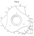
- the plate seat (25) shown in Figure 1 is with a Indexable insert (1), which three has rotationally symmetrical cutting units (2.3.4). there the respective roughing edge area (9) is through a main cutting edge (6) is formed, this in a short, straight front edge (5) and one with a Radius (23) formed cutting edge to the finishing edge area (27) divides.
- This can be the cutting edge also a straight chisel edge (8 ⁇ or through a broken line (24,24a) with an angle of can rise approx. 30 "and then at an angle of approx. 4 ° (24a) to be designed to run further.
- the finishing edge area (27) is through a straight finishing edge (7) formed, each in the direction of Milling axis (26) runs and to which a cross cutting edge (11) connects, this in about 45 ° to next cutting unit (3) runs.
- the frontal cutting edge (5) closes on the inside Area another cross cutting edge (10) in the form of a straight line or curve that connects to next cutting unit (4) forms.
- the seat shown (25) is designed so that with a different Distance (12) to the outer circumference a stepped Surface (13) revolves around the insert (1).
- This area (13) is designed such that three per cutting area Contact surfaces (13a, 13b, 13c) arise, two each Contact surfaces (13a, 13b) of adjacent cutting areas lie flush with one another on a line (33) and that the plate seat (25) is designed such that he has three contact surfaces (15a, 15b, 15c), which with the The contact surfaces of the indexable insert correspond and which protrude from the panel milling (16). How it got there the indexable insert to a three-point system.
- Fig. 3 shows an indexable insert (1) with a cross cutting edge (8) as a connecting cutting edge.
- Fig. 4 shows an indexable insert (1) with a broken connecting cutting edge (24, 24a).
- the plate seat (25) has a negative one Axial angle (26a) and a negative radial angle (17) on. This allows the clearance angle of the insert (1) 0 ° in some areas (la), and in the built-in Condition a clearance angle of approx. 7 ° -12 ° is achieved.
- the pivoting of the plate seat (25) both radial as well as axial has the advantages that the insert (1) Reinforced in their roughing area the indexable insert holder (14) reinforced in the foot area. So in Fig. 6 in the roughing area (21) of the insert (1) a set area (8a) of about 18 ° in the built-in Condition visible.
- the finishing edge (7) and the Finishing edge area (27) run parallel to Milling axis (26). This ensures that the Finishing edge (7) over the roughing edge (8,23,24a) protrudes approx.0.05 mm (32). Since the indexable insert (1) only with the main cutting edge (6), the finishing cutting edge (7) and the cross cutting edge (11) has come into cutting engagement the inside cutting area (6a) has no cutting intervention.
Landscapes
- Engineering & Computer Science (AREA)
- Mechanical Engineering (AREA)
- Milling Processes (AREA)
- Drilling Tools (AREA)
- Soil Working Implements (AREA)
- Preparation Of Fruits And Vegetables (AREA)
- Drilling And Exploitation, And Mining Machines And Methods (AREA)
- Earth Drilling (AREA)
Claims (5)
- Fraiseuse-aléseuse circulaire avec des plaquettes de coupe réversibles et des sièges de plaquettes correspondants pour usiner dans du matériau plein des poches, des trous oblongs, des alésages traversants, offrant la possibilité de détalonner, de chanfreiner en arrière et de fraiser des évidements déjà existants, étant observé quecaractérisée en ce que la plaquette de coupe réversible (1) comporte, d'une part, trois zones de coupe identiques (2), (3), (4) disposées l'une par rapport à l'autre avec un décalage de 120° dans le sens de la rotation, dont la lame frontale principale (6) se subdivise en une courte lame droite (5) et une lame présentant un rayon (23) formant transition vers la lame de finissage (7) et dont la lame transversale (11) entre la lame de finissage (7) et la prochaine zone de coupe (3) est formée d'une lame à chanfreiner, et, d'autre part, une surface étagée en retrait (13) de profondeur variable par rapport à la périphérie de la plaquette et s'étendant sur tout le pourtour de celle-ci de sorte que chaque zone de coupe présente trois surfaces d'appui (15a), (15b), (15c), étant précisé que deux surfaces d'appui (15a) et (15b) appartenant à des zones de coupe voisines (3), (4) sont alignées sur une même ligne (33), et en ce que le siège (25) de la plaquette de coupe est conçu de façon à présenter trois zones d'appui (13a), (13b), (13c) correspondant aux surfaces d'appui (15a), (15b), (15c) de la plaquette de coupe réversible (1) et qui sont saillantes sur le fraisage (16), et, est disposé avec simultanément un angle négatif de pivotement radial (17) et un angle négatif de rotation axiale (26a).la fraiseuse-aléseuse est entraínée en rotation par une machine à commande CNC sur une trajectoire avec avance continue selon l'axe Z ou est déplaçable partiellement sans avance selon l'axe Z lors de l'évidage de poches de grandes dimensions ou du fraisage sur fraiseuse à copier,chaque zone de coupe de la plaquette de coupe réversible comporte une lame frontale principale, une lame frontale secondaire avec des lames latérales extérieures et intérieures, une lame de finissage ainsi qu'une lame transversale assurant la transition entre la lame principale et la prochaine zone de coupe,la plaquette réversible comporte dans la zone de la lame principale une rainure pour la formation de copeaux,
- Fraiseuse-aléseuse circulaire avec des plaquettes de coupe réversibles et des sièges de plaquettes correspondants pour usiner dans du matériau plein des poches, des trous oblongs, des alésages traversants, offrant la possibilité de détalonner, de chanfreiner en arrière et de fraiser des évidements déjà existants, étant observé quecaractérisée en ce que la plaquette de coupe réversible (1) comporte, d'une part, trois zones de coupe identiques (2), (3), (4), disposées l'une par rapport à l'autre avec un décalage de 120° dans le sens de la rotation, dont la lame frontale principale (6) se subdivise en une courte lame droite (5) et une lame transversale (8) formant transition vers la lame de finissage et dont la lame transversale (11) entre la lame de finissage (7) et la prochaine zone de coupe (3) est formée d'une lame à chanfreiner, et, d'autre part, une surface étagée en retrait (13) de profondeur variable par rapport à la périphérie de la plaquette et s'étendant sur tout le pourtour de celle-ci de sorte que chaque zone de coupe présente trois surfaces d'appui (15a), (15b), (15c), étant précisé que deux surfaces d'appui (15a) et (15b) appartenant à des zones de coupe voisines (3), (4) sont alignées sur une même ligne (33), et en ce que le siège (25) de la plaquette de coupe est conçu de façon à présenter trois zones d'appui (13a), (13b), (13c) correspondant aux surfaces d'appui (15a), (15b), (15c) de la piaquette de coupe réversible (1) et qui sont saillantes sur le fraisage (16), et, est disposé avec simultanément un angle négatif de pivotement radial (17) et un angle négatif de rotation axiale (26a).la fraiseuse-aléseuse est entraínée en rotation par une machine à commande CNC sur une trajectoire avec avance continue selon l'axe Z ou est déplaçable partiellement sans avance selon l'axe Z lors de l'évidage de poches de grandes dimensions ou du fraisage sur fraiseuse à copier,chaque zone de coupe de la plaquette de coupe réversible comporte une lame frontale principale, une lame frontale secondaire avec des lames latérales extérieures et intérieures, une lame de finissage ainsi qu'une lame transversale assurant la transition entre la lame principale et la prochaine zone de coupe,la plaquette réversible comporte dans la zone de la lame principale une rainure pour la formation de copeaux,
- Fraiseuse-aléseuse circulaire avec des plaquettes de coupe réversibles et des sièges de plaquettes correspondants pour usiner dans du matériau plein des poches, des trous oblongs, des alésages traversants, offrant la possibilité de détalonner, de chanfreiner en arrière et de fraiser des évidements déjà existants, étant observé quecaractérisée en ce que la plaquette de coupe réversible (1) comporte, d'une part, trois zones de coupe identiques (2), (3), (4), disposées l'une par rapport à l'autre avec un décalage de 120° dans le sens de la rotation, dont la lame frontale principale (6) se subdivise en une courte lame droite (5) et une lame de transition vers la lame de finissage (7) ayant la forme d'une ligne coupée (24), (24a) et dont la lame transversale (11) entre la lame de finissage (7) et la prochaine zone de coupe (3) est formée d'une lame à chanfreiner, et, d'autre part, une surface étagée en retrait (13) de profondeur variable par rapport à la périphérie de la plaquette et s'étendant sur tout le pourtour de celle-ci de sorte que chaque zone de coupe présente trois surfaces d'appui (15a), (15b), (15c), étant précisé que deux surfaces d'appui (15a) et (15b) appartenant à des zones de coupe voisines (3), (4) sont alignées sur une même ligne (33), et en ce que le siège (25) de la plaquette de coupe est conçu de façon à présenter trois zones d'appui (13a), (13b), (13c) correspondant aux surfaces d'appui (15a), (15b), (15c) de la plaquette de coupe réversible (1) et qui sont saillantes sur le fraisage (16), et, est disposé avec simultanément un angle négatif de pivotement radial (17) et un angle négatif de rotation axiale (26a).la fraiseuse-aléseuse est entraínée en rotation par une machine à commande CNC sur une trajectoire avec avance continue selon l'axe Z ou est déplaçable partiellement sans avance selon l'axe Z lors de l'évidage de poches de grandes dimensions ou du fraisage sur fraiseuse à copier,chaque zone de coupe de la plaquette de coupe réversible comporte une lame frontale principale, une lame frontale secondaire avec des lames latérales extérieures et intérieures, une lame de finissage ainsi qu'une lame transversale assurant la transition entre la lame principale et la prochaine zone de coupe,la plaquette réversible comporte dans la zone de la lame principale une rainure pour la formation de copeaux,
- Fraiseuse-aléseuse circulaire selon l'une des revendications 1 à 3 caractérisée en ce que l'angle de dépouille (19a) de la plaquette de coupe réversible (1) après montage est compris entre 7° et 9° et qu'un angle de dépouille (20a) compris entre 9° et 11° est atteint dans la zone de coupe périphérique, l'angle de dépouille de la plaquette de coupe seule pouvant être de 0°.
- Fraiseuse-aléseuse circulaire selon l'une des revendications 1 à 4 caractérisée en ce que le siège (25) de la plaquette de coupe peut être utilisé également pour d'autres plaquettes de coupe réversibles.
Applications Claiming Priority (3)
| Application Number | Priority Date | Filing Date | Title |
|---|---|---|---|
| DE19709436A DE19709436C2 (de) | 1997-03-07 | 1997-03-07 | Zirkularbohrfräser |
| DE19709436 | 1997-03-07 | ||
| PCT/DE1998/000640 WO1998040183A1 (fr) | 1997-03-07 | 1998-03-03 | Fraise de perçage circulaire avec plaquettes amovibles et sieges de plaquette associes |
Publications (2)
| Publication Number | Publication Date |
|---|---|
| EP0964762A1 EP0964762A1 (fr) | 1999-12-22 |
| EP0964762B1 true EP0964762B1 (fr) | 2001-06-27 |
Family
ID=7822604
Family Applications (1)
| Application Number | Title | Priority Date | Filing Date |
|---|---|---|---|
| EP98916853A Expired - Lifetime EP0964762B1 (fr) | 1997-03-07 | 1998-03-03 | Fraise de percage circulaire avec plaquettes amovibles et sieges de plaquette associes |
Country Status (8)
| Country | Link |
|---|---|
| US (1) | US6213691B1 (fr) |
| EP (1) | EP0964762B1 (fr) |
| JP (1) | JP2001514580A (fr) |
| AT (1) | ATE202508T1 (fr) |
| AU (1) | AU7029998A (fr) |
| DE (3) | DE19709436C2 (fr) |
| ES (1) | ES2158680T3 (fr) |
| WO (1) | WO1998040183A1 (fr) |
Families Citing this family (23)
| Publication number | Priority date | Publication date | Assignee | Title |
|---|---|---|---|---|
| JP4304935B2 (ja) * | 2002-03-11 | 2009-07-29 | 三菱マテリアル株式会社 | 切削工具及びスローアウェイチップ |
| JP3775321B2 (ja) | 2002-03-20 | 2006-05-17 | 三菱マテリアル株式会社 | スローアウェイチップおよびスローアウェイ式切削工具 |
| WO2004105988A2 (fr) * | 2003-05-29 | 2004-12-09 | Arm Tooling, Inc. | Accessoire pour outil de coupe et corps d'outil a couper |
| DE102004019535A1 (de) * | 2004-04-22 | 2005-11-17 | MAPAL Fabrik für Präzisionswerkzeuge Dr. Kress KG | Messerplatte und Werkzeug zur spanenden Bearbeitung von Bohrungsoberflächen |
| DE102004026601A1 (de) * | 2004-06-01 | 2005-12-22 | Sandvik Ab | Wendeschneideinsatz zum Drehen |
| AT8743U1 (de) * | 2005-10-19 | 2006-12-15 | Ceratizit Austria Gmbh | Fräswerkzeug |
| DE102005054434B4 (de) * | 2005-11-15 | 2009-09-24 | Kennametal Inc. | Wendeschneidplatte mit zwei Teilkörpern |
| DE102006044605A1 (de) | 2006-09-19 | 2008-03-27 | Komet Group Holding Gmbh | Wendeschneidplatte sowie Verwendung der Wendeschneidplatte in einem Vollbohrer |
| SE531250C2 (sv) * | 2007-06-05 | 2009-02-03 | Sandvik Intellectual Property | Indexerbart hörnfrässkär |
| SE531858C2 (sv) * | 2007-12-21 | 2009-08-25 | Sandvik Intellectual Property | Fräsverktyg för spånavskiljande bearbetning, samt skärkropp och grundkropp härför |
| KR101314882B1 (ko) * | 2008-11-27 | 2013-10-14 | 대구텍 유한회사 | 양면형 절삭 인서트 및 이를 구비하는 절삭 공구 |
| DE102009034481A1 (de) * | 2009-07-22 | 2011-01-27 | AS GbR (vertretungsberechtigter Gesellschafter:Sadri Ibrahimi, 71665 Vaihingen) | Wendeschneidplatte |
| JP2013006221A (ja) * | 2009-10-13 | 2013-01-10 | Mitsubishi Materials Corp | 切削インサート及び刃先交換式回転工具 |
| KR20120083499A (ko) * | 2009-12-08 | 2012-07-25 | 가부시키가이샤 탕가로이 | 날끝 교환식 절삭공구 |
| JP5403167B2 (ja) * | 2010-09-30 | 2014-01-29 | 株式会社タンガロイ | 刃先交換式切削工具 |
| EP2478982A1 (fr) * | 2011-01-21 | 2012-07-25 | VARGUS Ltd. | Insert de coupe pour fileter et outil de coupe |
| EP2722122B1 (fr) * | 2011-06-17 | 2020-10-14 | Tungaloy Corporation | Plaquette de coupe et outil de coupe rotatif |
| US9421622B2 (en) * | 2014-01-14 | 2016-08-23 | Iscar, Ltd. | Indexable central drill insert and cutting tool therefor |
| US9700947B2 (en) | 2014-06-27 | 2017-07-11 | Kennametal Inc. | Ballnose cutting tool and ballnose cutting insert |
| CN110802285A (zh) * | 2019-10-30 | 2020-02-18 | 澳普洛钻探工具(无锡)有限公司 | 密封性钻杆外螺纹生产用刀具 |
| JP6919824B2 (ja) * | 2020-01-15 | 2021-08-18 | 株式会社タンガロイ | 切削インサート及び該切削インサートを用いた旋削工具 |
| US11534838B1 (en) * | 2021-06-08 | 2022-12-27 | Iscar, Ltd. | Indexable lay-down cutting insert having a central body portion and three circumferentially spaced cutting portions, and cutting tool |
| CN116748570B (zh) * | 2023-06-21 | 2026-05-12 | 浙江欣兴工具股份有限公司 | 一种高性能可转位钻头刀片组合及可转位钻头 |
Family Cites Families (10)
| Publication number | Priority date | Publication date | Assignee | Title |
|---|---|---|---|---|
| US4084917A (en) * | 1976-11-10 | 1978-04-18 | Zahnradfabrik Friedrichshafen Ag | Turning tool, especially for copying turning |
| DE3831046A1 (de) * | 1988-09-12 | 1990-03-15 | Felix Leeb | Hohlfraeser zur herstellug von kreisrunden ausnehmungen mit stufenlos veraenderlichem durchmesser |
| US4934878A (en) * | 1988-12-27 | 1990-06-19 | Gte Valenite Corporation | Center and peripheral cutting end mill |
| DE3909077C2 (de) * | 1989-03-20 | 1994-12-08 | Felix Leeb | Fräsbohrwerkzeug mit einem Schaft zur Herstellung von kreisrunden Ausnehmungen in Vollmaterial |
| DE9217148U1 (de) * | 1992-12-16 | 1994-04-14 | Leeb, Felix, 94405 Landau | Wendeplatten zum Passungs- und Gewindefräsen ins volle Material und dazu einen einfachen Plattensitz |
| DE4342577C2 (de) * | 1993-12-14 | 1997-10-02 | Kaspar Dipl Ing Emunds | Rückschlagventil |
| JP3376727B2 (ja) * | 1994-11-11 | 2003-02-10 | 三菱マテリアル株式会社 | スローアウェイ式エンドミル |
| IL115338A (en) * | 1995-09-18 | 1999-07-14 | Iscar Ltd | Exchangeable cutting insert and a tool assembly for use therewith |
| US5913644A (en) * | 1998-04-20 | 1999-06-22 | Kennametal Inc. | Helical mill having multiple flutes with differing rake angles |
| US6050752A (en) * | 1999-03-19 | 2000-04-18 | Kennametal Inc. | Cutting insert |
-
1997
- 1997-03-07 DE DE19709436A patent/DE19709436C2/de not_active Expired - Fee Related
-
1998
- 1998-03-03 DE DE59800929T patent/DE59800929D1/de not_active Expired - Fee Related
- 1998-03-03 DE DE19880267T patent/DE19880267D2/de not_active Ceased
- 1998-03-03 AU AU70299/98A patent/AU7029998A/en not_active Abandoned
- 1998-03-03 US US09/194,655 patent/US6213691B1/en not_active Expired - Fee Related
- 1998-03-03 EP EP98916853A patent/EP0964762B1/fr not_active Expired - Lifetime
- 1998-03-03 AT AT98916853T patent/ATE202508T1/de not_active IP Right Cessation
- 1998-03-03 ES ES98916853T patent/ES2158680T3/es not_active Expired - Lifetime
- 1998-03-03 JP JP53906698A patent/JP2001514580A/ja active Pending
- 1998-03-03 WO PCT/DE1998/000640 patent/WO1998040183A1/fr not_active Ceased
Also Published As
| Publication number | Publication date |
|---|---|
| DE19709436A1 (de) | 1998-09-10 |
| ATE202508T1 (de) | 2001-07-15 |
| ES2158680T3 (es) | 2001-09-01 |
| JP2001514580A (ja) | 2001-09-11 |
| EP0964762A1 (fr) | 1999-12-22 |
| WO1998040183A1 (fr) | 1998-09-17 |
| DE19880267D2 (de) | 2000-01-13 |
| US6213691B1 (en) | 2001-04-10 |
| DE59800929D1 (de) | 2001-08-02 |
| DE19709436C2 (de) | 1999-03-04 |
| AU7029998A (en) | 1998-09-29 |
Similar Documents
| Publication | Publication Date | Title |
|---|---|---|
| DE19709436C2 (de) | Zirkularbohrfräser | |
| EP1004380B1 (fr) | Fraise de précision avec plaquette de coupe | |
| EP1184116B1 (fr) | Outil de fraisage et de perçage | |
| DE10291948C5 (de) | Spanwerkzeug mit verbesserter Schneidplättchensitzanordnung für austauschbare Schneidplättchen | |
| DE60019929T2 (de) | Bohrer mit drei schneidkanten | |
| DE102015112417B4 (de) | Rotierendes Schneidwerkzeug mit nachschleifbaren Schneideinsätzen | |
| EP3758876B1 (fr) | Outil de chanfreinage, système de chanfreinage, machine à tailler des dentures et procédé servant à chanfreiner des dentures | |
| DE3610016C2 (fr) | ||
| EP0792709A2 (fr) | Méthode à usiner des rainures courbées et outil destiné à cet usinage | |
| DE4342557A1 (de) | Wendeschneidplatten zum Passungs- und Gewindefräsen ins volle Material und dazu einen einfachen Plattensitz | |
| EP1907158B1 (fr) | Element de coupe a inserer, outil et procede d'usinage d'une piece | |
| CH648226A5 (de) | In einem halter eines maschinenwerkzeuges, insbesondere drehwerkzeuges, einsetzbarer schneidplattentraeger. | |
| EP0334002A2 (fr) | Fraise de filetage | |
| EP0485546B1 (fr) | Garniture de coupe pour outils | |
| DE102017118738A1 (de) | Fräswerkzeug für eine Werkzeugmaschine, Fräsanordnung mit dem Fräswerkzeug sowie Verfahren zur Herstellung eines Kammkäfigs | |
| EP0264599B1 (fr) | Outil d'alésage | |
| DE19626608B4 (de) | Verfahren zur spanenden Bearbeitung | |
| DE102004008166A1 (de) | Werkzeug zur spanenden Bearbeitung von Präzisionsbohrungen | |
| WO2005037472A1 (fr) | Outil pour realiser des alesages et/ou usiner ces derniers | |
| DE3909643C2 (de) | Mehrschneidenwerkzeugkopf zur spanabhebenden Vor- und Feinbearbeitung mit kreisförmiger Schnittbewegung | |
| DE19915536C1 (de) | Bohrwerkzeug | |
| EP0780182A1 (fr) | Méthode à former une filetage interne et outil à utiliser cette méthode | |
| DE10144735B4 (de) | Schneideinsätze und Rotations-Umfangsfräser mit austauschbaren Schneideinsätzen | |
| DE102008049516B9 (de) | Verfahren zur spanenden Bearbeitung von Werkstückflächen an Werkstücken, insbesondere an Kurbelwellen, sowie Schneideinsatz zur Durchführung eines solchen Verfahrens | |
| DE2617455A1 (de) | Stechdrehmeissel |
Legal Events
| Date | Code | Title | Description |
|---|---|---|---|
| PUAI | Public reference made under article 153(3) epc to a published international application that has entered the european phase |
Free format text: ORIGINAL CODE: 0009012 |
|
| 17P | Request for examination filed |
Effective date: 19981130 |
|
| AK | Designated contracting states |
Kind code of ref document: A1 Designated state(s): AT BE CH DE DK ES FR GB IT LI LU NL PT SE |
|
| AX | Request for extension of the european patent |
Free format text: SI PAYMENT 19981130 |
|
| GRAG | Despatch of communication of intention to grant |
Free format text: ORIGINAL CODE: EPIDOS AGRA |
|
| GRAG | Despatch of communication of intention to grant |
Free format text: ORIGINAL CODE: EPIDOS AGRA |
|
| GRAH | Despatch of communication of intention to grant a patent |
Free format text: ORIGINAL CODE: EPIDOS IGRA |
|
| GRAH | Despatch of communication of intention to grant a patent |
Free format text: ORIGINAL CODE: EPIDOS IGRA |
|
| 17Q | First examination report despatched |
Effective date: 20000728 |
|
| GRAA | (expected) grant |
Free format text: ORIGINAL CODE: 0009210 |
|
| AK | Designated contracting states |
Kind code of ref document: B1 Designated state(s): AT BE CH DE DK ES FR GB IT LI LU NL PT SE |
|
| AX | Request for extension of the european patent |
Free format text: SI PAYMENT 19981130 |
|
| PG25 | Lapsed in a contracting state [announced via postgrant information from national office to epo] |
Ref country code: NL Free format text: LAPSE BECAUSE OF FAILURE TO SUBMIT A TRANSLATION OF THE DESCRIPTION OR TO PAY THE FEE WITHIN THE PRESCRIBED TIME-LIMIT Effective date: 20010627 Ref country code: GB Free format text: LAPSE BECAUSE OF FAILURE TO SUBMIT A TRANSLATION OF THE DESCRIPTION OR TO PAY THE FEE WITHIN THE PRESCRIBED TIME-LIMIT Effective date: 20010627 Ref country code: FR Free format text: LAPSE BECAUSE OF FAILURE TO SUBMIT A TRANSLATION OF THE DESCRIPTION OR TO PAY THE FEE WITHIN THE PRESCRIBED TIME-LIMIT Effective date: 20010627 |
|
| REF | Corresponds to: |
Ref document number: 202508 Country of ref document: AT Date of ref document: 20010715 Kind code of ref document: T |
|
| REG | Reference to a national code |
Ref country code: CH Ref legal event code: EP |
|
| REG | Reference to a national code |
Ref country code: CH Ref legal event code: NV Representative=s name: A. BRAUN, BRAUN, HERITIER, ESCHMANN AG PATENTANWAE |
|
| REF | Corresponds to: |
Ref document number: 59800929 Country of ref document: DE Date of ref document: 20010802 |
|
| REG | Reference to a national code |
Ref country code: ES Ref legal event code: FG2A Ref document number: 2158680 Country of ref document: ES Kind code of ref document: T3 |
|
| ITF | It: translation for a ep patent filed | ||
| PG25 | Lapsed in a contracting state [announced via postgrant information from national office to epo] |
Ref country code: SE Free format text: LAPSE BECAUSE OF FAILURE TO SUBMIT A TRANSLATION OF THE DESCRIPTION OR TO PAY THE FEE WITHIN THE PRESCRIBED TIME-LIMIT Effective date: 20010927 Ref country code: PT Free format text: LAPSE BECAUSE OF FAILURE TO SUBMIT A TRANSLATION OF THE DESCRIPTION OR TO PAY THE FEE WITHIN THE PRESCRIBED TIME-LIMIT Effective date: 20010927 Ref country code: DK Free format text: LAPSE BECAUSE OF FAILURE TO SUBMIT A TRANSLATION OF THE DESCRIPTION OR TO PAY THE FEE WITHIN THE PRESCRIBED TIME-LIMIT Effective date: 20010927 |
|
| NLV1 | Nl: lapsed or annulled due to failure to fulfill the requirements of art. 29p and 29m of the patents act | ||
| EN | Fr: translation not filed | ||
| GBV | Gb: ep patent (uk) treated as always having been void in accordance with gb section 77(7)/1977 [no translation filed] |
Effective date: 20010627 |
|
| PG25 | Lapsed in a contracting state [announced via postgrant information from national office to epo] |
Ref country code: LU Free format text: LAPSE BECAUSE OF NON-PAYMENT OF DUE FEES Effective date: 20020303 |
|
| PGFP | Annual fee paid to national office [announced via postgrant information from national office to epo] |
Ref country code: AT Payment date: 20020314 Year of fee payment: 5 |
|
| PG25 | Lapsed in a contracting state [announced via postgrant information from national office to epo] |
Ref country code: LI Free format text: LAPSE BECAUSE OF NON-PAYMENT OF DUE FEES Effective date: 20020331 Ref country code: CH Free format text: LAPSE BECAUSE OF NON-PAYMENT OF DUE FEES Effective date: 20020331 Ref country code: BE Free format text: LAPSE BECAUSE OF NON-PAYMENT OF DUE FEES Effective date: 20020331 |
|
| PLBE | No opposition filed within time limit |
Free format text: ORIGINAL CODE: 0009261 |
|
| STAA | Information on the status of an ep patent application or granted ep patent |
Free format text: STATUS: NO OPPOSITION FILED WITHIN TIME LIMIT |
|
| 26N | No opposition filed | ||
| BERE | Be: lapsed |
Owner name: *LEEB FELIX Effective date: 20020331 |
|
| PG25 | Lapsed in a contracting state [announced via postgrant information from national office to epo] |
Ref country code: DE Free format text: LAPSE BECAUSE OF NON-PAYMENT OF DUE FEES Effective date: 20021001 |
|
| REG | Reference to a national code |
Ref country code: CH Ref legal event code: PL |
|
| PG25 | Lapsed in a contracting state [announced via postgrant information from national office to epo] |
Ref country code: AT Free format text: LAPSE BECAUSE OF NON-PAYMENT OF DUE FEES Effective date: 20030303 |
|
| PGFP | Annual fee paid to national office [announced via postgrant information from national office to epo] |
Ref country code: ES Payment date: 20080318 Year of fee payment: 11 |
|
| PGFP | Annual fee paid to national office [announced via postgrant information from national office to epo] |
Ref country code: IT Payment date: 20080328 Year of fee payment: 11 |
|
| REG | Reference to a national code |
Ref country code: ES Ref legal event code: FD2A Effective date: 20090304 |
|
| PG25 | Lapsed in a contracting state [announced via postgrant information from national office to epo] |
Ref country code: ES Free format text: LAPSE BECAUSE OF NON-PAYMENT OF DUE FEES Effective date: 20090304 |
|
| PG25 | Lapsed in a contracting state [announced via postgrant information from national office to epo] |
Ref country code: IT Free format text: LAPSE BECAUSE OF NON-PAYMENT OF DUE FEES Effective date: 20090303 |