EP0964778B1 - Laufrolle - Google Patents
Laufrolle Download PDFInfo
- Publication number
- EP0964778B1 EP0964778B1 EP97937531A EP97937531A EP0964778B1 EP 0964778 B1 EP0964778 B1 EP 0964778B1 EP 97937531 A EP97937531 A EP 97937531A EP 97937531 A EP97937531 A EP 97937531A EP 0964778 B1 EP0964778 B1 EP 0964778B1
- Authority
- EP
- European Patent Office
- Prior art keywords
- hub
- tread
- casing
- roller
- tread roller
- Prior art date
- Legal status (The legal status is an assumption and is not a legal conclusion. Google has not performed a legal analysis and makes no representation as to the accuracy of the status listed.)
- Expired - Lifetime
Links
- 239000000463 material Substances 0.000 claims abstract description 32
- 230000002093 peripheral effect Effects 0.000 claims description 15
- 238000009826 distribution Methods 0.000 claims description 9
- 238000000034 method Methods 0.000 abstract description 4
- 239000004033 plastic Substances 0.000 description 12
- 229920003023 plastic Polymers 0.000 description 12
- 238000005266 casting Methods 0.000 description 6
- 238000004519 manufacturing process Methods 0.000 description 6
- 229910052782 aluminium Inorganic materials 0.000 description 5
- XAGFODPZIPBFFR-UHFFFAOYSA-N aluminium Chemical compound [Al] XAGFODPZIPBFFR-UHFFFAOYSA-N 0.000 description 5
- 238000002347 injection Methods 0.000 description 4
- 239000007924 injection Substances 0.000 description 4
- 229910052751 metal Inorganic materials 0.000 description 3
- 239000002184 metal Substances 0.000 description 3
- 238000000465 moulding Methods 0.000 description 3
- 239000000243 solution Substances 0.000 description 3
- 229920001169 thermoplastic Polymers 0.000 description 3
- 239000004604 Blowing Agent Substances 0.000 description 2
- 235000004443 Ricinus communis Nutrition 0.000 description 2
- 230000015572 biosynthetic process Effects 0.000 description 2
- 229920001971 elastomer Polymers 0.000 description 2
- 239000000806 elastomer Substances 0.000 description 2
- 208000015943 Coeliac disease Diseases 0.000 description 1
- JOYRKODLDBILNP-UHFFFAOYSA-N Ethyl urethane Chemical compound CCOC(N)=O JOYRKODLDBILNP-UHFFFAOYSA-N 0.000 description 1
- 240000000528 Ricinus communis Species 0.000 description 1
- 239000000956 alloy Substances 0.000 description 1
- 229910045601 alloy Inorganic materials 0.000 description 1
- 230000004323 axial length Effects 0.000 description 1
- 230000006835 compression Effects 0.000 description 1
- 238000007906 compression Methods 0.000 description 1
- 230000006735 deficit Effects 0.000 description 1
- 230000001771 impaired effect Effects 0.000 description 1
- 238000001746 injection moulding Methods 0.000 description 1
- 238000003780 insertion Methods 0.000 description 1
- 230000037431 insertion Effects 0.000 description 1
- 238000003754 machining Methods 0.000 description 1
- 239000007769 metal material Substances 0.000 description 1
- 239000000203 mixture Substances 0.000 description 1
- 229920000642 polymer Polymers 0.000 description 1
- 229920002635 polyurethane Polymers 0.000 description 1
- 239000004814 polyurethane Substances 0.000 description 1
- 238000012805 post-processing Methods 0.000 description 1
- 238000012545 processing Methods 0.000 description 1
- 239000003380 propellant Substances 0.000 description 1
- 238000000926 separation method Methods 0.000 description 1
- 238000003892 spreading Methods 0.000 description 1
- 239000004416 thermosoftening plastic Substances 0.000 description 1
Images


Classifications
-
- B—PERFORMING OPERATIONS; TRANSPORTING
- B29—WORKING OF PLASTICS; WORKING OF SUBSTANCES IN A PLASTIC STATE IN GENERAL
- B29D—PRODUCING PARTICULAR ARTICLES FROM PLASTICS OR FROM SUBSTANCES IN A PLASTIC STATE
- B29D99/00—Subject matter not provided for in other groups of this subclass
- B29D99/0032—Producing rolling bodies, e.g. rollers, wheels, pulleys or pinions
-
- A—HUMAN NECESSITIES
- A63—SPORTS; GAMES; AMUSEMENTS
- A63C—SKATES; SKIS; ROLLER SKATES; DESIGN OR LAYOUT OF COURTS, RINKS OR THE LIKE
- A63C17/00—Roller skates; Skate-boards
- A63C17/22—Wheels for roller skates
- A63C17/223—Wheel hubs
-
- B—PERFORMING OPERATIONS; TRANSPORTING
- B29—WORKING OF PLASTICS; WORKING OF SUBSTANCES IN A PLASTIC STATE IN GENERAL
- B29C—SHAPING OR JOINING OF PLASTICS; SHAPING OF MATERIAL IN A PLASTIC STATE, NOT OTHERWISE PROVIDED FOR; AFTER-TREATMENT OF THE SHAPED PRODUCTS, e.g. REPAIRING
- B29C45/00—Injection moulding, i.e. forcing the required volume of moulding material through a nozzle into a closed mould; Apparatus therefor
- B29C45/14—Injection moulding, i.e. forcing the required volume of moulding material through a nozzle into a closed mould; Apparatus therefor incorporating preformed parts or layers, e.g. injection moulding around inserts or for coating articles
- B29C45/14311—Injection moulding, i.e. forcing the required volume of moulding material through a nozzle into a closed mould; Apparatus therefor incorporating preformed parts or layers, e.g. injection moulding around inserts or for coating articles using means for bonding the coating to the articles
-
- B—PERFORMING OPERATIONS; TRANSPORTING
- B29—WORKING OF PLASTICS; WORKING OF SUBSTANCES IN A PLASTIC STATE IN GENERAL
- B29C—SHAPING OR JOINING OF PLASTICS; SHAPING OF MATERIAL IN A PLASTIC STATE, NOT OTHERWISE PROVIDED FOR; AFTER-TREATMENT OF THE SHAPED PRODUCTS, e.g. REPAIRING
- B29C45/00—Injection moulding, i.e. forcing the required volume of moulding material through a nozzle into a closed mould; Apparatus therefor
- B29C45/14—Injection moulding, i.e. forcing the required volume of moulding material through a nozzle into a closed mould; Apparatus therefor incorporating preformed parts or layers, e.g. injection moulding around inserts or for coating articles
- B29C45/1459—Coating annular articles
-
- B—PERFORMING OPERATIONS; TRANSPORTING
- B29—WORKING OF PLASTICS; WORKING OF SUBSTANCES IN A PLASTIC STATE IN GENERAL
- B29C—SHAPING OR JOINING OF PLASTICS; SHAPING OF MATERIAL IN A PLASTIC STATE, NOT OTHERWISE PROVIDED FOR; AFTER-TREATMENT OF THE SHAPED PRODUCTS, e.g. REPAIRING
- B29C45/00—Injection moulding, i.e. forcing the required volume of moulding material through a nozzle into a closed mould; Apparatus therefor
- B29C45/14—Injection moulding, i.e. forcing the required volume of moulding material through a nozzle into a closed mould; Apparatus therefor incorporating preformed parts or layers, e.g. injection moulding around inserts or for coating articles
- B29C45/14311—Injection moulding, i.e. forcing the required volume of moulding material through a nozzle into a closed mould; Apparatus therefor incorporating preformed parts or layers, e.g. injection moulding around inserts or for coating articles using means for bonding the coating to the articles
- B29C2045/14327—Injection moulding, i.e. forcing the required volume of moulding material through a nozzle into a closed mould; Apparatus therefor incorporating preformed parts or layers, e.g. injection moulding around inserts or for coating articles using means for bonding the coating to the articles anchoring by forcing the material to pass through a hole in the article
-
- B—PERFORMING OPERATIONS; TRANSPORTING
- B29—WORKING OF PLASTICS; WORKING OF SUBSTANCES IN A PLASTIC STATE IN GENERAL
- B29K—INDEXING SCHEME ASSOCIATED WITH SUBCLASSES B29B, B29C OR B29D, RELATING TO MOULDING MATERIALS OR TO MATERIALS FOR MOULDS, REINFORCEMENTS, FILLERS OR PREFORMED PARTS, e.g. INSERTS
- B29K2705/00—Use of metals, their alloys or their compounds, for preformed parts, e.g. for inserts
- B29K2705/02—Aluminium
-
- B—PERFORMING OPERATIONS; TRANSPORTING
- B29—WORKING OF PLASTICS; WORKING OF SUBSTANCES IN A PLASTIC STATE IN GENERAL
- B29L—INDEXING SCHEME ASSOCIATED WITH SUBCLASS B29C, RELATING TO PARTICULAR ARTICLES
- B29L2031/00—Other particular articles
- B29L2031/32—Wheels, pinions, pulleys, castors or rollers, Rims
Definitions
- the invention relates to a roller according to the Preamble of claim 1.
- a hard material is used for the hub, for example a Duroplastic or a metallic material used
- a softer material such as a thermoplastic or an elastomer such as cast urethane
- air pockets in the tread shell arise. Apart from the appearance of the roller that is impaired by this can such air pockets to detach the tread shell from the Lead hub.
- EP-A-0 298 356 discloses a method for producing a plastic part as well as this component.
- a metallic insert such as a roller bearing or a sliding bush in a molding tool under injection or compression pressure in embedded a polymer plastic mass.
- the polymeric plastic mass is subjected to impermissible loads during manufacture a blowing agent is added.
- the molding tool is used after insertion of the insert with the plastic mass with propellant admixture under one comparatively low pressure filled.
- the blowing agent in the mold a pressure built up, through which the plastic mass to form a Tread against the mold and against the outer circumference of the insert expanded.
- the component produced in this way can be used, for example, as a belt tensioner be used
- the intermediate shells only cover part of the outer circumferential surface of the hub.
- the non-rotatable connection between the intermediate jacket and the tread jacket can be achieved in different ways. So, depending on the material for the intermediate jacket, a material connection between the intermediate jacket and tread jacket. There is also the possibility that the Non-rotatable connection between the intermediate casing and the tread casing takes place, for example, in such a way that the intermediate jacket openings or has undercuts into which the material for the Tread shell can flow during the manufacturing process, so that Form fit is present.
- the intermediate jacket at least one, preferably at least two approximately radially extending and at least partially ring-shaped on the Outer peripheral surface has circumferential elevations.
- These surveys can be provided with the openings already mentioned, which for a et al positive connection between intermediate jacket and tread jacket are provided.
- this can also be done be designed so that one of the occurring pressure or force distribution at Use the contoured roller insert. This can be done, for example achieved that the two elevations in cross section at least approximately are pyramid-shaped or camel-like.
- the mutually facing sides of the elevation diverge from the outer peripheral surface the hub from in the radial direction to its outer, preferably rounded End up. Since the pressure distribution in the cross section of the Considered roller, essentially takes a parabolic shape, is by the Solution proposed above achieves that the contour of the two surveys this parabolic curve is adapted to the pressure distribution. The result can be achieve a longer life of the roller, especially if the Roller is exposed to high speeds because of the adapted contour the elevations detach the tread shell from the hub or the Intermediate jacket is avoided.
- the intermediate jacket has on it with the Tread mantle in contact with surfaces without edges, especially sharp edges or burrs.
- the mantle has bumps , it has proven to be advantageous if at least these surveys their radial outer ends are rounded.
- the outer peripheral surface of the hub has a recess into which the intermediate jacket is axially fixed.
- two or more intermediate coats are provided, two or more recesses or only one only recess for receiving all intermediate shells can be provided.
- the intermediate jacket also with the hub is rotationally fixed, but not releasably connected.
- the intermediate jacket be shrunk or vulcanized onto the hub.
- the hub is off made of a high quality material so that when the tread shell wears out a repeated use of the hub is possible, it can also be provided be that the intermediate jacket detachable, preferably by screw is held on the hub. This can then by loosening the screw Intermediate jacket and possibly the remains of the still on the intermediate jacket tread shell located can be removed from the hub and the hub a new application, in particular a new manufacturing process for manufacturing a new rollers are fed.
- the The tread jacket can then already be replaced by the user can, if the tread is still intact, not yet completely worn out is.
- the releasable attachment of the intermediate jacket can, for example, thereby happen that the intermediate jacket is attached to the hub by means of screws, the essentially radially extending threaded bores of the hub are screwable.
- the hub can be designed so that it Has spokes in which the threaded holes are provided.
- the intermediate jacket with itself radially inwards extending fastening tab is provided when attaching the intermediate jacket can be fixed by the screw. This can be done, for example happen that the mounting tabs have through holes through which the Screws can be inserted.
- the hub can be placed on at least two in a hub radial plane Hub halves is formed, which are rotatably connected together. It has proven particularly advantageous here if the division of the Hub into the two hub halves in the radial plane of symmetry of the hub.
- the hub halves an inner ring and an outer ring have preferably three, at least approximately radially extending Crosspieces are connected to one another, the crosspieces for receiving the screwing means are provided. It can further be provided that in one One half of the hub has a through hole and one in the other half of the hub Threaded hole, preferably provided as a blind hole.
- the intermediate jacket can not be removed or be detachably attached to the hub.
- the screw means for fixing the two halves of the hub also hold the intermediate coat.
- the two Hub halves define a space on their sides facing each other, if they are placed on top of each other in the fastening tabs of the Intermediate sheath are recordable.
- the mounting tabs point in this case a passage opening through which the screw means is passed can be.
- the hub is made of metal, preferably aluminum, for example Die-cast aluminum, or an alloy thereof is made.
- metal preferably aluminum, for example Die-cast aluminum, or an alloy thereof is made.
- the above-mentioned occurs Especially problem of formation of bubbles when pouring the tread shell clearly due to the burrs and / or sharp edges of the Metal hub there is a stall during casting and thus air bubbles arise.
- the intermediate jacket now provided in this case this problem elegantly solved, since the material of the tread shell is not or only slightly comes into contact with the metal surface of the hub. It can the intermediate jacket should be designed so that it has no or very few has sharp edges.
- the intermediate jacket only has, or at least largely, rounded surfaces, so that no stall at Pouring is done.
- the intermediate sheath made of a plastic preferably a hard plastic such as ABS, PAG etc.
- the intermediate coat itself can be manufactured, for example, by an injection molding process.
- any suitable material can be provided for the material of the tread shell be because of the arrangement of the intermediate jacket on the material the hub does not have to be considered. It has come in handy proven if the material for the tread shell is a thermoplastic Plastic that is more recyclable, or an elastomer, preferably polyurethane is used.
- the roller according to the invention is also intended to pose such a risk counteract. This happens according to the invention in that the hub on their outer circumferential surface one of the pressure distribution when using the roller has an adapted contour.
- the hub can have both an intermediate jacket have the shape described above, as well as without such Intermediate jacket.
- the contour adapted to the pressure distribution when using the roller can be on be formed in different ways. For example, it turned out to be Appropriately proven that two to each other on the outer peripheral surface of the hub spaced, radially extending and at least in sections in the circumferential direction circumferential rings of the hub are provided, their facing each other Converge sides toward the outer peripheral surface of the hub. Through this Convergence is the course of the two rings the course of the pressure distribution adapted, whereby high mileage is achieved even at high speeds can be.
- the rings at least one have approximately trapezoidal cross-section and / or the two rings symmetrical to the radial symmetry axis of the hub on the outer peripheral surface are arranged.
- the Rings viewed in the axial direction of the hub, spaced from the hub edge are arranged.
- the rings can be used to produce a positive fit Connection between the hub and the tread shell with openings be provided. These openings can either be oval holes in the Be rings or be open radially outwards, also in the axial direction the hub considered, at least approximately the shape of an upside down Have the letter "T".
- a roller 110 according to the invention shown in FIGS. 1 and 2 has one Hub 120 made of an aluminum material, preferably die-cast aluminum, an intermediate jacket 130 made of a hard plastic, in particular of ABS or PAG, and a tread shell 140 made of a preferably thermoplastic Plastic on.
- the hub 120 is made of a first one Hub half 122, which is shown in more detail in Figures 5 and 6, and from a second hub half 124, which is shown in more detail in FIGS. 7 and 8 is shown.
- the two hub halves 122, 124 are in a radial plane of symmetry R of the roller 110 placed on top of each other. For better orientation are in the figure 5 parts of the total roller 110 still represented by phantom lines.
- the two hub halves 122, 124 each have an inner ring 122a, 124a and an outer ring 122b, 124b.
- the inner rings 122a, 124a and the outer rings 122b, 124b of the two Hub halves 122, 124 are each separated by three radially extending webs or Spokes 122c, 124c connected together.
- the webs 22c, 24c are each in an approximately 120 ° division to each other.
- the webs 122c of the first hub half 122 have, as is particularly the case Figure 6 shows through holes 122ca which are used to receive Screws 126 serve as will be explained below.
- the right-hand end is the through hole 122ca provided with a countersink 122cb.
- the first is Hub half 122 on its outer ring 122b on the, also related to figure 6, right end face with a radially outwardly projecting annular web 122ba Mistake.
- This ring web 122ba defines together with that in the corresponding
- the intermediate casing 130 is axially fixed by the two ring webs 122ba, 124ba held in the recess 128.
- the first hub half 122 is on its side Inner circumferential surface 122d provided with a bearing receiving surface 122e, which is from that, based on FIG. 6, of the right end of the first hub half 122 extends axially into the first half of the hub 122.
- a Diameter reduction is a paragraph not specified, which is formed as Contact surface for the bearing accommodated in the bearing surface 122e serves.
- the first half of the hub faces 122 is arranged on its side facing the second hub half 124 Ring 122f on, together with an appropriately designed ring recess 124f of the second hub half 124 forms a centering device, which the stacking of the two hub halves 122, 124 relieved.
- the centering ring 122f or the annular centering recess 124f are each on the inner ring 122a, 124a arranged.
- the second hub half is shown in FIGS. 7 and 8 and is except for the Differences explained below are constructed in the same way as those in the figures 5 and 6, the first half of the hub 122.
- FIGS. 7 and 8 are the matching components of the second hub half 124 with the same Letters as in the first half of the hub 122 marked only with the Difference that instead of the reference number "122", the reference number "124" is used.
- blind holes 124ca are provided in contrast to the first hub half 122.
- the second hub half 124 in their webs 124c blind holes 124ca, each with a thread are provided in this connection.
- blind holes 124ca are shown with visible lines, although they are in the viewing direction 7 are not recognizable.
- the intermediate jacket 130 is used, as can be seen in particular from FIG. 2.
- the intermediate casing 130 shown in FIGS. 3 and 4 has on its inner peripheral surface 132 three radially inwardly extending fastening tabs 134, which are also arranged in an approximately 120 ° division.
- the tabs 134 are provided with through holes 134a through which the already above mentioned screws 126 passed through when assembling the hub 120 can be.
- the intermediate jacket 130 is also with two pyramidal or camel-shaped, radially outward and annular around elevations 136 surrounding the outer circumferential surface of the intermediate casing 130 provided, as can be seen from Figures 3 and 4. How in particular 4 can be seen, the two elevations 136 are symmetrical to Radial symmetry plane S of the intermediate shell 130 arranged with the Radial symmetry plane R of the roller 110 coincides.
- the camel-like ones Elevations 136 have openings 136a, which, like this in particular can be seen from Figure 3, have an oval shape, the "main axis" of the Ovals runs essentially in the circumferential direction.
- the radially outward pointing ends 136b of the elevations 136 and the unspecified The edges of the openings are, as can be seen in particular from FIG. 4, rounded.
- the intermediate jacket 130 is first on the second hub half 124 placed in such a way that the fastening tabs 134th rest on the webs 124c of the second hub half 124 and thereby the Bore axes of the openings 134a of these mounting tabs 134 with the Drill axes of the blind holes 124ca are aligned. So with the first one on Hub half 122 the fastening tabs 134 of the intermediate jacket 130 without Increase in the axial length of the two stacked hub halves 122, 124 or the overall hub 120 can be accommodated between them, form the two Na halves 122, 124 on their sides facing each other Recess 129, in which the fastening tabs 134 are received can, as shown in Figure 2.
- first hub half 22 placed on the second hub half 124 in such a way that the webs 122c of the first hub half 122 with the fastening tab 130 and the webs 124c of the second half of the hub and the bore axes of the through bores 122ca of the first hub half 122 with the bore axes of the Through bores 134a of the fastening tabs 134 and the bore axes of the blind holes 124ca of the second half of the hub 124 are aligned.
- the fastening screws 126 are screwed in and thereby the two hub halves 122, 124 attached to each other, with the Intermediate casing 130 by means of its fastening tabs 134 so as to rotate with the hub 120 is connected.
- the hub 120 thus produced can then be inserted into an appropriate molding tool be inserted and after further preparatory measures that for the Tread shell 140 necessary plastic material entered into the mold become.
- the material for the tread shell 140 also flows into the Through openings 136a of the intermediate jacket 136. After curing the material for the tread shell 140 is thereby a positive non-rotatable connection between the intermediate jacket 130 and the Tread shell 140. Since the intermediate shell 130 is already rotatably on the hub 120 is attached, this in turn creates a non-rotatable connection between the tread shell 140 and the hub 120.
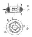
- FIGS. 11 and 12 show a further embodiment of the invention Castor shown.
- the known roller 200 has the outer circumference 220a of its hub 220 several extending radially outwards, in the radial plane of symmetry R of Roller 200 arranged T-shaped extensions 202, the undercuts form, through which the tread shell 240 rotatably with the hub 220 of the known roller 200 is connected.
- these extensions 202 are just in the area of the highest pressure occurring when the roller 200 is used, as shown schematically in FIG.
- the cross section of the tread shell 240 can be reduced this results in a particularly rapid wear of the tread shell 240 up to occur to detach the tread shell 240 from the hub 220.
- a roller 300 which has two axially spaced apart, has radially extending rings 306, 308 made of T-shaped extensions.
- This T-shaped extensions 302 have a trapezoidal cross-section like this is shown in Figure 12.
- the two rings 306, 308 are from the extensions 302 arranged so that the sides facing each other in the direction of Outer peripheral surface 320a of hub 320 converge to each other like this also emerges from Figure 12.
- the outer peripheral surface 320a is the The contour of the hub 320 that occurs when the roller 300 is used Pressure distribution adjusted, as shown in Figure 12.
Landscapes
- Engineering & Computer Science (AREA)
- Mechanical Engineering (AREA)
- Manufacturing & Machinery (AREA)
- Rolls And Other Rotary Bodies (AREA)
- Massaging Devices (AREA)
- Moulds For Moulding Plastics Or The Like (AREA)
Description
- Figur 1
- eine Ansicht auf eine erfindungsgemäße Laufrolle;
- Figur 2
- einen Schnitt durch die in Figur 1 dargestellte Laufrolle entlang der Linie VII-VII in Figur 1;
- Figur 3
- eine Ansicht auf einen Zwischenmantel, der bei der in Figur 1 gezeigten Laufrolle Verwendung findet;
- Figur 4
- einen Schnitt durch den in Figur 3 gezeigten Zwischenmantel entlang der Linie IX-IX in Figur 3;
- Figur 5
- eine Ansicht einer ersten Nabenhälfte der in Figur 1 gezeigten Laufrolle;
- Figur 6
- einen Schnitt durch die in Figur 5 gezeigte, erste Nabenhälfte entlang der Linie XI-XI in Figur 5;
- Figur 7
- eine Ansicht einer zweiten Nabenhälfte der in Figur 1 gezeigten Laufrolle;
- Figur 8
- einen Schnitt durch die in Figur 7 gezeigte, zweite Nabenhälfte entlang der Linie XIII-XIII in Figur 7;
- Figur 9
- eine Ansicht einer bekannten Laufrolle;
- Figur 10
- einen Schnitt durch die in Figur 9 gezeigte, bekannte Laufrolle entlang der Linie XV-XV in Figur 9,
- Figur 11
- eine Ansicht einer weiteren erfindungsgemäßen Laufrolle; und
- Figur 12
- einen Schnitt durch die in Figur 11 gezeigte Laufrolle entlang der Linie XVI-XVI in Figur 11.
Claims (8)
- Laufrolle, insbesonders für Inline-Skater, mit einer Nabe (120) und einem an der Nabe (120) drehfest angeformten, die Lauffläche aufweisenden Lauflächenmantel (140), wobei die Nabe (120) an ihrer Außenumfangsfläche (120a) mit wenigstens einem drehfest, mit ihr verbundenen Zwischenmantel (130) versehen ist, an dem zumindest teilweise der Laufflächenmantel (140) drehfest angeformt ist,
dadurch gekennzeichnet, daß der Zwischenmantel (130) mit sich radial einwärtserstreckenden Befestigungslappen (134) versehen ist, die mittels lösbarer Befestigungsmittel (126) anbringbar sind, wenn der Zwischenmantel (130) an der Nabe (120) angebracht wird. - Laufrolle nach Anspruch 1,
dadurch gekennzeichnet, daß die drehfeste Verbindung zwischen Zwischenmantel (130) und Laufflächenmantel (140) stoff- und/oder formschlüssig erfolgt. - Laufrolle nach Anspruch 1 oder 2,
dadurch gekennzeichnet, daß der Zwischenmantel (130) wenigstens eine, vorzugsweise zwei sich zumindest annähernd radial erstreckende und zumindest abschnittsweise ringförmig an der Außenumfangsfläche (120a) umlaufende Erhebungen (136) aufweist. - Laufrolle nach Anspruch 3,
dadurch gekennzeichnet, daß die Erhebungen (136) mit sich zumindest annähernd parallel zur Achse (A) der Nabe (120) erstreckenden Durchbrechungen (136a) versehen sind. - Laufrolle nach Anspruch 6 oder 7,
dadurch gekennzeichnet, daß die Erhebungen (136) im Querschnitt zumindest annähernd pyramidenförmig ausgebildet sind. - Laufrolle nach einem der Ansprüche 1 bis 5,
dadurch gekennzeichnet, daß zumindest ein Teil der in Kontakt mit dem Laufflächenmantel (140) kommenden Ecken und/oder Kanten des Zwischenmantels (130) abgerundet sind. - Laufrollen nach einem der Ansprüche 1 bis 6,
dadurch gekennzeichnet, daß die Nabe (120) aus wenigstens zwei in einer Nabenradialebene (R) aufeinandersetzbare Nabenhälften (122, 124) gebildet ist, die drehfest miteinander verbunden sind. - Laufrolle nach einem der Ansprüche 1 bis 7,
dadurch gekennzeichnet, daß die Nabe (320) an ihrer Außenumfangsfläche (320a) eine der Druckverteilung beim Einsatz der Laufrolle (300) angepaßte Kontur besitzt.
Applications Claiming Priority (5)
| Application Number | Priority Date | Filing Date | Title |
|---|---|---|---|
| DE19630811 | 1996-07-31 | ||
| DE1996130811 DE19630811C1 (de) | 1996-07-31 | 1996-07-31 | Laufrolle |
| DE19715721 | 1997-04-15 | ||
| DE1997115721 DE19715721A1 (de) | 1997-04-15 | 1997-04-15 | Laufrolle mit Zwischenmantel |
| PCT/EP1997/004151 WO1998004400A1 (de) | 1996-07-31 | 1997-07-30 | Laufrolle |
Publications (2)
| Publication Number | Publication Date |
|---|---|
| EP0964778A1 EP0964778A1 (de) | 1999-12-22 |
| EP0964778B1 true EP0964778B1 (de) | 2003-04-09 |
Family
ID=26027953
Family Applications (1)
| Application Number | Title | Priority Date | Filing Date |
|---|---|---|---|
| EP97937531A Expired - Lifetime EP0964778B1 (de) | 1996-07-31 | 1997-07-30 | Laufrolle |
Country Status (4)
| Country | Link |
|---|---|
| EP (1) | EP0964778B1 (de) |
| AT (1) | ATE236786T1 (de) |
| DE (1) | DE59709807D1 (de) |
| WO (1) | WO1998004400A1 (de) |
Families Citing this family (2)
| Publication number | Priority date | Publication date | Assignee | Title |
|---|---|---|---|---|
| EP2830848B1 (de) | 2012-03-30 | 2016-10-19 | Magna International Inc. | Kunststoffumgiessung von aluminiumextrusionen |
| IT201800004696A1 (it) * | 2018-04-19 | 2019-10-19 | Ruota con sistema di ancoraggio fra pneumatico solido e cerchio |
Family Cites Families (8)
| Publication number | Priority date | Publication date | Assignee | Title |
|---|---|---|---|---|
| DE945072C (de) * | 1953-08-18 | 1956-06-28 | Ernst Rennebaum Dipl Kfm | Spielzeuglaufrad |
| FR2462596A1 (fr) * | 1979-07-25 | 1981-02-13 | Paris & Du Rhone | Perfectionnements aux organes tournant en matiere plastique tels que les ventilateurs |
| GB2084508A (en) * | 1980-09-30 | 1982-04-15 | Eventhall Leon Harry | Moulding |
| US4588542A (en) * | 1981-05-04 | 1986-05-13 | G. P. Plastics, Inc. | Bicycle wheel assembly |
| DE3212318C1 (de) * | 1982-04-02 | 1983-07-21 | Triumph-Adler Aktiengesellschaft für Büro- und Informationstechnik, 8500 Nürnberg | Verfahren zur Herstellung von einstueckigen Typenscheibenrohlingen fuer Schreib- oder aehnliche Maschinen sowie nach diesem Verfahren hergestellte Typenscheibenrohlinge |
| JPH0225962Y2 (de) * | 1984-11-12 | 1990-07-16 | ||
| DE3722052A1 (de) * | 1987-07-03 | 1989-01-12 | Schaeffler Waelzlager Kg | Verfahren zum herstellen eines kunststoffteils und bauteil |
| US5312844A (en) * | 1993-05-14 | 1994-05-17 | S&W Plastics, Inc. | Method of producing polyurethane injection molded in-line skate wheels |
-
1997
- 1997-07-30 WO PCT/EP1997/004151 patent/WO1998004400A1/de not_active Ceased
- 1997-07-30 DE DE59709807T patent/DE59709807D1/de not_active Expired - Lifetime
- 1997-07-30 AT AT97937531T patent/ATE236786T1/de not_active IP Right Cessation
- 1997-07-30 EP EP97937531A patent/EP0964778B1/de not_active Expired - Lifetime
Also Published As
| Publication number | Publication date |
|---|---|
| EP0964778A1 (de) | 1999-12-22 |
| ATE236786T1 (de) | 2003-04-15 |
| DE59709807D1 (de) | 2003-05-15 |
| WO1998004400A1 (de) | 1998-02-05 |
Similar Documents
| Publication | Publication Date | Title |
|---|---|---|
| DE69729945T2 (de) | Fräser | |
| DE69929551T2 (de) | Zusammengesetztes, diametralgeteiltes, sphärisches Lager und Herstellungsverfahren | |
| DE69913271T2 (de) | Verbundwerkstoffschwungrad | |
| DE3840869C2 (de) | Anordnung zur Befestigung eines harten Lagerringes in der Bohrungsfläche eines Gehäuses oder auf der Mantelfläche eines Zapfens | |
| EP1024081B1 (de) | Blattwurzel für Propeller- und Rotorblätter | |
| EP1053847A2 (de) | Formeinsatz | |
| EP0306738B1 (de) | Vorrichtung zum Einpressen und Abziehen von Lagern oder Hülsen, insbesondere für Achslager und/oder Radflanschnaben an Kraftfahrzeugen | |
| DE9406691U1 (de) | Vorrichtung zur Verbindung von Lagerringen | |
| DE3217458C2 (de) | Einstückig aus einer Leichtmetallegierung gegossenes oder geschmiedetes Rad für Kraftfahrzeuge, sowie Verfahren zu seiner Herstellung | |
| DE60320424T2 (de) | Run-flat-vorrichtung | |
| DE3690665C2 (de) | ||
| DE3504322C2 (de) | ||
| DE102016117104A1 (de) | Mehrteiliges, gefedertes Schienenrad | |
| DE2105292A1 (de) | Gehorschutz | |
| EP0807025A1 (de) | Fahrzeugrad und verfahren zur herstellung desselben | |
| EP0636217B1 (de) | Verfahren zum herstellen einer bremsscheibe für eine scheibenbremse | |
| DE69305145T2 (de) | Bremsrotor aus Verbundwerkstoff | |
| DE8713304U1 (de) | Mittenfreies Wälzlager | |
| DE19543516C2 (de) | Transportelement für flächiges Gut | |
| EP0897780A2 (de) | Werkzeug zum Entfernen von Klebstoffresten oder dergleichen von Unterlagen | |
| DE19715721A1 (de) | Laufrolle mit Zwischenmantel | |
| DE19630811C1 (de) | Laufrolle | |
| DE202004018828U1 (de) | Geschmiedeter Spannsatz | |
| DE2815698C3 (de) | Spritzgieß- oder Preßform zur Verarbeitung plastischer Massen | |
| EP0964778A1 (de) | Laufrolle |
Legal Events
| Date | Code | Title | Description |
|---|---|---|---|
| PUAI | Public reference made under article 153(3) epc to a published international application that has entered the european phase |
Free format text: ORIGINAL CODE: 0009012 |
|
| 17P | Request for examination filed |
Effective date: 19980327 |
|
| AK | Designated contracting states |
Kind code of ref document: A1 Designated state(s): AT BE CH DE FR GB IT LI NL |
|
| RBV | Designated contracting states (corrected) |
Designated state(s): AT BE CH DE FR GB IT LI NL |
|
| 17Q | First examination report despatched |
Effective date: 20000621 |
|
| GRAG | Despatch of communication of intention to grant |
Free format text: ORIGINAL CODE: EPIDOS AGRA |
|
| RAP1 | Party data changed (applicant data changed or rights of an application transferred) |
Owner name: KISTNER, ROLF |
|
| RIN1 | Information on inventor provided before grant (corrected) |
Inventor name: KISTNER, ROLF |
|
| GRAG | Despatch of communication of intention to grant |
Free format text: ORIGINAL CODE: EPIDOS AGRA |
|
| GRAH | Despatch of communication of intention to grant a patent |
Free format text: ORIGINAL CODE: EPIDOS IGRA |
|
| GRAH | Despatch of communication of intention to grant a patent |
Free format text: ORIGINAL CODE: EPIDOS IGRA |
|
| GRAA | (expected) grant |
Free format text: ORIGINAL CODE: 0009210 |
|
| AK | Designated contracting states |
Designated state(s): AT BE CH DE FR GB IT LI NL |
|
| PG25 | Lapsed in a contracting state [announced via postgrant information from national office to epo] |
Ref country code: NL Free format text: LAPSE BECAUSE OF FAILURE TO SUBMIT A TRANSLATION OF THE DESCRIPTION OR TO PAY THE FEE WITHIN THE PRESCRIBED TIME-LIMIT Effective date: 20030409 Ref country code: GB Free format text: LAPSE BECAUSE OF FAILURE TO SUBMIT A TRANSLATION OF THE DESCRIPTION OR TO PAY THE FEE WITHIN THE PRESCRIBED TIME-LIMIT Effective date: 20030409 |
|
| REG | Reference to a national code |
Ref country code: GB Ref legal event code: FG4D Free format text: NOT ENGLISH |
|
| REG | Reference to a national code |
Ref country code: CH Ref legal event code: EP |
|
| REG | Reference to a national code |
Ref country code: CH Ref legal event code: NV Representative=s name: PATENTANWAELTE SCHAAD, BALASS, MENZL & PARTNER AG |
|
| NLV1 | Nl: lapsed or annulled due to failure to fulfill the requirements of art. 29p and 29m of the patents act | ||
| GBV | Gb: ep patent (uk) treated as always having been void in accordance with gb section 77(7)/1977 [no translation filed] |
Effective date: 20030409 |
|
| ET | Fr: translation filed | ||
| PGFP | Annual fee paid to national office [announced via postgrant information from national office to epo] |
Ref country code: BE Payment date: 20040212 Year of fee payment: 7 |
|
| PLBE | No opposition filed within time limit |
Free format text: ORIGINAL CODE: 0009261 |
|
| STAA | Information on the status of an ep patent application or granted ep patent |
Free format text: STATUS: NO OPPOSITION FILED WITHIN TIME LIMIT |
|
| 26N | No opposition filed |
Effective date: 20040112 |
|
| PGFP | Annual fee paid to national office [announced via postgrant information from national office to epo] |
Ref country code: AT Payment date: 20040608 Year of fee payment: 7 |
|
| PG25 | Lapsed in a contracting state [announced via postgrant information from national office to epo] |
Ref country code: AT Free format text: LAPSE BECAUSE OF NON-PAYMENT OF DUE FEES Effective date: 20040730 |
|
| PG25 | Lapsed in a contracting state [announced via postgrant information from national office to epo] |
Ref country code: BE Free format text: LAPSE BECAUSE OF NON-PAYMENT OF DUE FEES Effective date: 20040731 |
|
| PGFP | Annual fee paid to national office [announced via postgrant information from national office to epo] |
Ref country code: CH Payment date: 20041231 Year of fee payment: 8 |
|
| BERE | Be: lapsed |
Owner name: *KISTNER ROLF Effective date: 20040731 |
|
| PG25 | Lapsed in a contracting state [announced via postgrant information from national office to epo] |
Ref country code: IT Free format text: LAPSE BECAUSE OF NON-PAYMENT OF DUE FEES;WARNING: LAPSES OF ITALIAN PATENTS WITH EFFECTIVE DATE BEFORE 2007 MAY HAVE OCCURRED AT ANY TIME BEFORE 2007. THE CORRECT EFFECTIVE DATE MAY BE DIFFERENT FROM THE ONE RECORDED. Effective date: 20050730 |
|
| PG25 | Lapsed in a contracting state [announced via postgrant information from national office to epo] |
Ref country code: LI Free format text: LAPSE BECAUSE OF NON-PAYMENT OF DUE FEES Effective date: 20050731 Ref country code: CH Free format text: LAPSE BECAUSE OF NON-PAYMENT OF DUE FEES Effective date: 20050731 |
|
| REG | Reference to a national code |
Ref country code: CH Ref legal event code: PL |
|
| BERE | Be: lapsed |
Owner name: *KISTNER ROLF Effective date: 20040731 |
|
| REG | Reference to a national code |
Ref country code: FR Ref legal event code: ST Effective date: 20080229 |
|
| PG25 | Lapsed in a contracting state [announced via postgrant information from national office to epo] |
Ref country code: FR Free format text: LAPSE BECAUSE OF NON-PAYMENT OF DUE FEES Effective date: 20030731 |
|
| PGFP | Annual fee paid to national office [announced via postgrant information from national office to epo] |
Ref country code: DE Payment date: 20140731 Year of fee payment: 18 |
|
| REG | Reference to a national code |
Ref country code: DE Ref legal event code: R119 Ref document number: 59709807 Country of ref document: DE |
|
| PG25 | Lapsed in a contracting state [announced via postgrant information from national office to epo] |
Ref country code: DE Free format text: LAPSE BECAUSE OF NON-PAYMENT OF DUE FEES Effective date: 20160202 |