EP0964807B1 - Cadre pour fixer des elements plats - Google Patents
Cadre pour fixer des elements plats Download PDFInfo
- Publication number
- EP0964807B1 EP0964807B1 EP98912261A EP98912261A EP0964807B1 EP 0964807 B1 EP0964807 B1 EP 0964807B1 EP 98912261 A EP98912261 A EP 98912261A EP 98912261 A EP98912261 A EP 98912261A EP 0964807 B1 EP0964807 B1 EP 0964807B1
- Authority
- EP
- European Patent Office
- Prior art keywords
- frame
- wall structure
- profiled
- section
- cold
- Prior art date
- Legal status (The legal status is an assumption and is not a legal conclusion. Google has not performed a legal analysis and makes no representation as to the accuracy of the status listed.)
- Expired - Lifetime
Links
- 229920002430 Fibre-reinforced plastic Polymers 0.000 claims description 2
- 239000011151 fibre-reinforced plastic Substances 0.000 claims description 2
- 238000005304 joining Methods 0.000 abstract description 3
- 238000004519 manufacturing process Methods 0.000 description 6
- 239000000463 material Substances 0.000 description 6
- 238000003698 laser cutting Methods 0.000 description 3
- 239000002184 metal Substances 0.000 description 3
- 238000013000 roll bending Methods 0.000 description 3
- 239000000853 adhesive Substances 0.000 description 2
- 230000001070 adhesive effect Effects 0.000 description 2
- 239000012790 adhesive layer Substances 0.000 description 2
- 238000009434 installation Methods 0.000 description 2
- 238000000034 method Methods 0.000 description 2
- 230000006978 adaptation Effects 0.000 description 1
- 238000004026 adhesive bonding Methods 0.000 description 1
- 238000005452 bending Methods 0.000 description 1
- 239000004918 carbon fiber reinforced polymer Substances 0.000 description 1
- 150000001875 compounds Chemical class 0.000 description 1
- 238000010276 construction Methods 0.000 description 1
- 238000011161 development Methods 0.000 description 1
- 230000018109 developmental process Effects 0.000 description 1
- 230000000694 effects Effects 0.000 description 1
- 239000011152 fibreglass Substances 0.000 description 1
- 239000003292 glue Substances 0.000 description 1
- 238000012423 maintenance Methods 0.000 description 1
- 230000007246 mechanism Effects 0.000 description 1
- 239000004033 plastic Substances 0.000 description 1
- 229920003023 plastic Polymers 0.000 description 1
- 239000002994 raw material Substances 0.000 description 1
- 238000007789 sealing Methods 0.000 description 1
- 238000007493 shaping process Methods 0.000 description 1
- 125000006850 spacer group Chemical group 0.000 description 1
- 239000003351 stiffener Substances 0.000 description 1
- 230000007704 transition Effects 0.000 description 1
- 239000013585 weight reducing agent Substances 0.000 description 1
Images

Classifications
-
- B—PERFORMING OPERATIONS; TRANSPORTING
- B61—RAILWAYS
- B61D—BODY DETAILS OR KINDS OF RAILWAY VEHICLES
- B61D25/00—Window arrangements peculiar to rail vehicles
Definitions
- the invention relates to a wall structure with a frame consisting of profile parts and, for the mutual connection of cold-available connecting means for Fasten surface elements, especially window surfaces, to the wall structure according to the features of the preamble of claim 1.
- the document DE-A-44 04 846 discloses window frames for adhesive glazing, by gluing and / or locking four straight plastic profile parts can be assembled cold-joined with separate corner connections. Cold joining techniques are also preferably used to attach these frames to a wall structure applied.
- EP-A-0 515 953 discloses a window frame which is not discussed as such as such for glazing flush with the outer skin, with screws on one side of the structure Carrier frame is attached. The screws can either be from the inside or be accessible from the outside of the wall structure.
- Bodies e.g. B. for railway passenger cars, as is well known, have between two load-bearing, contour-giving columns or frames of the side walls larger cutouts for installing windows and / or flaps. These sections are included Double-decker carriages on both the lower and upper floors. In the lower floor area the outer wall is often flat, while in the upper floor area it is curved in the roof merges.
- the invention is therefore based on the object of a framework of the initially discussed Specify a type that is particularly, but not exclusively, for a highly mechanized Production in the sense of a rework-free fitting to the given a flat or curved wall structure.
- the frame for a flap e.g. maintenance flap for units in the roof area l appropriate hinges and closures on the to attach the specified positions of the individual parts.
- the individual parts of the frame are joined using cold joints (punch rivets, pressure joining) warp-free and preferably made of metallic tube and / or folded profiles. You can also use a hybrid construction apply by removing such frame parts that do not need to be cold formed glass or carbon fiber reinforced plastic profiles (e.g. pultrusion material) be produced, and thus a noticeable weight reduction compared achieve metallic profile parts.
- cold joints punch rivets, pressure joining
- the precision and accuracy of fit of the individual parts is preferably by laser cutting ensured.
- Fasteners for flap hinges on the frame and closures (holes, recesses), possibly also for hinged window mechanisms, can then be introduced during the mechanized production of the frame parts become.
- the frame is also designed with contact surfaces to the body structure, so that you can fix it with distortion-free cold joint connections can.
- These contact surfaces are preferably with positioning aids correspond to provide the structure side in the vicinity of the recesses are.
- Such a frame is always between two pillars of a wall structure arrange, and its - directly upright in a wall structure - cross bars attach to it.
- Its longitudinal spars, which extend in the longitudinal direction of the wall structure may extend along longitudinal struts (buckling stiffeners, purlins) be attached or to fit in their longitudinal course.
- the Frame parts also include support surfaces for attaching an outer skin. On such a frame also does not need to have webs that cover the glazing or flap Border on the side. Because it is used between two pillars anyway and his Support surface is recessed, form the columns and, if necessary, upper and lower longitudinal profiles the lateral structure of the wall structure, between which the surface element is to fit.
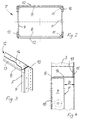
- a wall structure 1 - here a side wall section of a double-decker railway passenger car - is constructed modularly from module elements 2 with longitudinally oriented separating joints. Their shape and contour is largely determined by columns or frames 3. Their ends are connected to one another by edge profiles 4 placed along the parting lines. Connecting elements (not shown in more detail) fix the modules to one another at the ends of abutting frame sections. In this way, circumferential columns are formed from successive frame sections.
- the frames 3, the edge profiles 4 and longitudinally oriented purlins 5 form contact surfaces for an outer skin sheet not shown here.
- the wall structure 1 has an adapted to the clearance profile, curved contour.
- the shaping curvature in the longitudinal course of the concerned Frame sections are produced fully mechanically by CNC-controlled roll bending.
- window cutouts 6 for the installation of Windows (or flaps) provided in the upper floor area within the curved surface.
- this frame 7 will have to be used to support surfaces for glazing or to form the flaps mentioned.
- the distance of the Frames 3 directly determine the maximum window or flap width.
- the above-mentioned highly flexible production method of the frames should also be used for the frame 7.
- these consist of two parallel longitudinal spars 8 and transverse spars 9, which are cold-joined to one another at cross-sectional overlaps in the corner regions of the frame 7, as will be described in more detail below.
- Blind rivets are preferably used as connecting means, which can be inserted into predrilled holes and then tightened.
- the upright crossbars that run parallel to the frames 3 when installed 9 of the frames are made of closed hollow profile or tubular material without laterally projecting webs. This allows one of undesirable cross-sectional changes largely free cold deformation of the longitudinal profile, in particular by Roll bending.
- the cross section of the cross bars is somewhat flatter than the frame cross section, because of the difference in thickness, the lowering of the contact surface for the glazing compared to the outer skin. If the window packs should be glued, the cross-sectional width must be sufficiently wide for this.
- a conceivable fastening alternative - among others - is the window package from one side on the frame 7 and from the other side with To fasten screws or the like releasably. Even then, the frame forms the contact surface, however, its spars may be less wide than the adhesive solution.
- the cross bars are dimensionally accurate - preferably through Laser cutting - cut from the raw material and then into the desired curvature bent. Thereafter, recesses can be made to reduce weight into the wall parts that do not serve as the supporting surface for the glazing the crossbars are introduced, preferably again by laser cutting. in the The holes for inserting the blind rivets are the same step manufactured.
- the longitudinal bars 8 of the frame 7 have essentially one Bending made of sheet metal U-cross section.
- One of the two parallel ones Leg is part of the bearing surface of frame 7. This leg is in turn sufficiently wide to dimemise the glazing securely.
- Both ends of the longitudinal spars 8 are in one piece with connecting surfaces or elements 10 provided. These are obviously higher than the legs of the rest of the U-section. In the transition area you can see to avoid notch effects and to increase the shear rigidity of the frame 7 rounding surfaces 11, the can protrude at the corners into the rectangular free frame cross section.
- the longitudinal bars 8 can be cut out from sheet metal blanks (with a laser) the connection and rounding surfaces and, if necessary, in one operation Holes for pushing through connecting elements such as screws, rivets or Lockbolts are generated. Then they are folded into their Brought to its final shape.
- the longitudinal bars can also, as already mentioned at the beginning, as molded parts with all the necessary openings and holes are made of fiber reinforced plastic, so that this creates a hybrid material frame 7.
- the lateral positioning of the frame 7 on the wall structure is predetermined by the frames 3 or their spacing from one another.
- Angle rails 12 are provided, which extend along the longitudinal spars 8 of the Frame 7 extend.
- the angle rails 12 can have a leg 13 projecting from the frame 7 before mounting the frame 7 on the outer skin and / or on the columns 3 are attached.
- the respective U-web of the longitudinal spar 8 becomes against its other leg 14 created and in turn firmly connected with rivets or the like.
- angle rails shown here other ones may also be used longitudinal profiles occur, which are to be provided in the framework structure anyway. These can then also have other cross-sectional shapes, e.g. B. as tube profiles be executed.
- the dimension D in FIG. 4 thus denotes the thickness of those to be inserted on the frame 7 Glazing or flap including an adhesive layer or seal thickness and the Thickness of the outer skin 15 indicated here.
- the same dimension D also denotes approximately the difference between the thickness of the cross bars 9 of the frame 7 and the frames 3, the respective rear sides of which by means of the connecting surfaces 10 are aligned flush. So you can lower the bearing surface F compared to the outer skin surface very simply by an appropriate choice of Define the dimensions of the frames and cross bars. Tolerance compensation is on no longer necessary at this point. If necessary, minor Dimensional deviations can be compensated for by specifying an adhesive layer thickness.
- the side surfaces of the frames 3 directed towards the frame 7 form in the whole Installation arrangement, the lateral boundary or contact surfaces for the glazing, to attach to the wall structure 1 after attaching the frame 7 is.
- the — approximately horizontal — legs 14 of the angle profiles 12 the upper or lower contact surfaces.
Landscapes
- Engineering & Computer Science (AREA)
- Mechanical Engineering (AREA)
- Securing Of Glass Panes Or The Like (AREA)
- Connection Of Plates (AREA)
- Joining Of Corner Units Of Frames Or Wings (AREA)
- Die Bonding (AREA)
Claims (6)
- Structure de paroi (1) avec des cadres (7) se composant de pièces profilées (8, 9) et, pour leur assemblage mutuel, de moyens d'assemblage à assembler à froid pour la fixation d'un élément plat à la structure de paroi (1), caractérisée en ce que les pièces profilées (8, 9) sont applicables, au moyen d'éléments de jonction (10) façonnés sur celles-ci, à la structure de paroi à partir d'un côté de la structure de paroi (1) réalisée avec une épaisseur déterminée, dans laquelle il se forme, par une différence d'épaisseur du cadre (7) par rapport à la structure de paroi (1), un retrait clairement prédéterminé (D) d'une face d'appui (F) pour l'élément plat par rapport au côté opposé de la structure de paroi (1).
- Structure de paroi (1) avec des cadres (7) suivant la revendication 1, caractérisée en ce que les pièces profilées (8, 9) forment une face d'appui (F) pour appliquer l'élément plat sans nervures latérales, dans laquelle des faces d'appui ou de limitation latérales destinées au positionnement de l'élément plat sont formées directement par des pièces contiguës (3, 12, 14) de la structure de paroi (1).
- Structure de paroi (1) avec des cadres (7) suivant la revendication 1 ou 2, caractérisée en ce que des pièces profilées (9) à adapter à une structure de paroi (1) avec un contour courbe se composent d'un profil creux fermé déformable à froid à une forme courbe prédéterminée, sans modification de la section transversale.
- Structure de paroi (1) avec des cadres (7) suivant l'une quelconque des revendications précédentes, se composant de longerons longitudinaux et transversaux (8, 9), qui sont assemblés par des assemblages à froid dans des zones de chevauchement des sections transversales.
- Structure de paroi (1) avec des cadres (7) suivant l'une quelconque des revendications précédentes, caractérisée en ce que les pièces profilées (8) ne devant pas être soumises à une déformation à froid se composent de matière synthétique renforcée par des fibres.
- Structure de paroi (1) avec des cadres (7) suivant l'une quelconque des revendications précédentes, caractérisée en ce que les longerons longitudinaux (8) sont réalisés avec une section transversale en U avec des éléments de jonction (10) prévus aux extrémités.
Applications Claiming Priority (3)
| Application Number | Priority Date | Filing Date | Title |
|---|---|---|---|
| DE19708840 | 1997-03-05 | ||
| DE19708840A DE19708840C2 (de) | 1997-03-05 | 1997-03-05 | Rahmen zum Befestigen von Flächenelementen |
| PCT/DE1998/000471 WO1998039190A1 (fr) | 1997-03-05 | 1998-02-18 | Cadre pour fixer des elements plats |
Publications (2)
| Publication Number | Publication Date |
|---|---|
| EP0964807A1 EP0964807A1 (fr) | 1999-12-22 |
| EP0964807B1 true EP0964807B1 (fr) | 2001-08-29 |
Family
ID=7822228
Family Applications (1)
| Application Number | Title | Priority Date | Filing Date |
|---|---|---|---|
| EP98912261A Expired - Lifetime EP0964807B1 (fr) | 1997-03-05 | 1998-02-18 | Cadre pour fixer des elements plats |
Country Status (4)
| Country | Link |
|---|---|
| EP (1) | EP0964807B1 (fr) |
| AT (1) | ATE204818T1 (fr) |
| DE (2) | DE19708840C2 (fr) |
| WO (1) | WO1998039190A1 (fr) |
Cited By (11)
| Publication number | Priority date | Publication date | Assignee | Title |
|---|---|---|---|---|
| DE10248654B4 (de) * | 2002-10-18 | 2007-02-22 | Daimlerchrysler Ag | Verfahren zum Herstellen einer Kraftfahrzeugkarosserie und Kraftfahrzeugkarosserie |
| CN106274937A (zh) * | 2016-10-21 | 2017-01-04 | 苏州大成电子科技有限公司 | 一种高安全性的全景观列车车厢 |
| CN106347391A (zh) * | 2016-10-21 | 2017-01-25 | 苏州大成电子科技有限公司 | 一种高强度的全景观列车车厢 |
| CN106364507A (zh) * | 2016-10-21 | 2017-02-01 | 苏州大成电子科技有限公司 | 一种透光性好的全景观列车车厢 |
| CN106364502A (zh) * | 2016-10-18 | 2017-02-01 | 苏州大成电子科技有限公司 | 一种全景旅游列车车厢 |
| CN106379352A (zh) * | 2016-10-18 | 2017-02-08 | 苏州大成电子科技有限公司 | 一种全景车厢 |
| CN106394572A (zh) * | 2016-10-21 | 2017-02-15 | 苏州大成电子科技有限公司 | 一种耐磨的全景观列车车厢 |
| CN106428069A (zh) * | 2016-10-18 | 2017-02-22 | 苏州大成电子科技有限公司 | 一种全景旅游车厢 |
| CN106497158A (zh) * | 2016-10-21 | 2017-03-15 | 苏州大成电子科技有限公司 | 一种环保的全景观列车车厢 |
| CN106494438A (zh) * | 2016-10-21 | 2017-03-15 | 苏州大成电子科技有限公司 | 一种观赏性好的全景观列车车厢 |
| CN106627614A (zh) * | 2016-10-21 | 2017-05-10 | 苏州大成电子科技有限公司 | 一种防水防油的全景观列车车厢 |
Families Citing this family (3)
| Publication number | Priority date | Publication date | Assignee | Title |
|---|---|---|---|---|
| DE10051919A1 (de) * | 2000-10-19 | 2002-05-02 | Alstom Lhb Gmbh | Fenstereinbausystem für Fahrzeuge |
| DE102017216908A1 (de) * | 2017-09-25 | 2019-03-28 | Siemens Mobility GmbH | Fenstervorrichtung für ein Schienenfahrzeug |
| CN110667619A (zh) * | 2019-10-22 | 2020-01-10 | 中铁轨道交通装备有限公司 | 一种铰接式高地板有轨电车侧墙结构 |
Family Cites Families (5)
| Publication number | Priority date | Publication date | Assignee | Title |
|---|---|---|---|---|
| EP0347132A3 (fr) * | 1988-06-13 | 1991-02-27 | Hitachi, Ltd. | Caisse de véhicule ferroviaire |
| GB2257190A (en) * | 1991-05-25 | 1993-01-06 | Heywood Williams Ltd | Vehicle panel assembly, preferably for glazing |
| FR2679592A1 (fr) * | 1991-07-12 | 1993-01-29 | Klein Ets Georges | Vitrage, notamment pour fenetre de vehicule ferroviaire ou routier. |
| GB2275290A (en) * | 1993-02-19 | 1994-08-24 | Jenbacher Transportsysteme | Window frame |
| DE19619617C1 (de) * | 1996-05-15 | 1997-07-03 | Waggonfabrik Talbot Gmbh & Co | Verbindung zwischen zwei Bauteilen und modulares Bauteil |
-
1997
- 1997-03-05 DE DE19708840A patent/DE19708840C2/de not_active Expired - Fee Related
-
1998
- 1998-02-18 DE DE59801311T patent/DE59801311D1/de not_active Expired - Fee Related
- 1998-02-18 AT AT98912261T patent/ATE204818T1/de not_active IP Right Cessation
- 1998-02-18 EP EP98912261A patent/EP0964807B1/fr not_active Expired - Lifetime
- 1998-02-18 WO PCT/DE1998/000471 patent/WO1998039190A1/fr not_active Ceased
Cited By (11)
| Publication number | Priority date | Publication date | Assignee | Title |
|---|---|---|---|---|
| DE10248654B4 (de) * | 2002-10-18 | 2007-02-22 | Daimlerchrysler Ag | Verfahren zum Herstellen einer Kraftfahrzeugkarosserie und Kraftfahrzeugkarosserie |
| CN106364502A (zh) * | 2016-10-18 | 2017-02-01 | 苏州大成电子科技有限公司 | 一种全景旅游列车车厢 |
| CN106379352A (zh) * | 2016-10-18 | 2017-02-08 | 苏州大成电子科技有限公司 | 一种全景车厢 |
| CN106428069A (zh) * | 2016-10-18 | 2017-02-22 | 苏州大成电子科技有限公司 | 一种全景旅游车厢 |
| CN106274937A (zh) * | 2016-10-21 | 2017-01-04 | 苏州大成电子科技有限公司 | 一种高安全性的全景观列车车厢 |
| CN106347391A (zh) * | 2016-10-21 | 2017-01-25 | 苏州大成电子科技有限公司 | 一种高强度的全景观列车车厢 |
| CN106364507A (zh) * | 2016-10-21 | 2017-02-01 | 苏州大成电子科技有限公司 | 一种透光性好的全景观列车车厢 |
| CN106394572A (zh) * | 2016-10-21 | 2017-02-15 | 苏州大成电子科技有限公司 | 一种耐磨的全景观列车车厢 |
| CN106497158A (zh) * | 2016-10-21 | 2017-03-15 | 苏州大成电子科技有限公司 | 一种环保的全景观列车车厢 |
| CN106494438A (zh) * | 2016-10-21 | 2017-03-15 | 苏州大成电子科技有限公司 | 一种观赏性好的全景观列车车厢 |
| CN106627614A (zh) * | 2016-10-21 | 2017-05-10 | 苏州大成电子科技有限公司 | 一种防水防油的全景观列车车厢 |
Also Published As
| Publication number | Publication date |
|---|---|
| WO1998039190A1 (fr) | 1998-09-11 |
| DE19708840A1 (de) | 1998-09-17 |
| EP0964807A1 (fr) | 1999-12-22 |
| ATE204818T1 (de) | 2001-09-15 |
| DE19708840C2 (de) | 1999-04-08 |
| DE59801311D1 (de) | 2001-10-04 |
Similar Documents
| Publication | Publication Date | Title |
|---|---|---|
| EP0608761B1 (fr) | Structure de caisse de voiture, notamment ferroviaire | |
| DE102007036366B4 (de) | Fahrzeugdach mit einem Dachmodul | |
| EP0622289B1 (fr) | Carrosserie pour véhicules à moteur | |
| EP0964807B1 (fr) | Cadre pour fixer des elements plats | |
| DE19506160A1 (de) | Rahmenkonstruktion für Kraftfahrzeuge | |
| EP0461345A1 (fr) | Carrosserie pour un véhicule automobile, en particulier pour une voiture de tourisme | |
| EP1373053A1 (fr) | Dispositif de renforcement d'un element creux | |
| EP1911662B1 (fr) | Fond de caisse d'un véhicule et système de plate-forme | |
| EP2030877B1 (fr) | Châssis de véhicule doté d'un élément de toit | |
| DE102010014962A1 (de) | Außenwand für einen Schienenfahrzeug-Wagenkasten und Verfahren zu dessen Herstellung | |
| DE19612342C1 (de) | Aufbau für Fahrzeuge | |
| EP0501226B1 (fr) | Carrosserie pour véhicules et procédé de sa manufacture | |
| DE102008021224B4 (de) | Schienenfahrzeug | |
| DE20211949U1 (de) | Tür für Kraftfahrzeuge und Verbindung der Ränder von Kraftfahrzeugtürblechen | |
| EP2559609B1 (fr) | Cadre de renfort et procédé de mise en place d'un cadre de renfort dans une carrosserie de véhicule | |
| EP1108640B1 (fr) | Fixation de toiture de véhicules automobiles | |
| EP0855978B1 (fr) | Element modulaire et procede de fabrication | |
| DE19946013B4 (de) | Seitengerippe für eine selbsttragende Karosserie eines Kraftfahrzeuges | |
| DE19628305A1 (de) | Schienenfahrzeug | |
| DE19807747B4 (de) | Karosserieabschnitt eines Kraftfahrzeuges | |
| DE19538793C2 (de) | Modulelement | |
| DE3610769C2 (fr) | ||
| DE4330014A1 (de) | Kraftfahrzeug, insbesondere Van | |
| DE3424690C2 (de) | Selbsttragende Omnibus-Karosserie | |
| EP1652755A1 (fr) | Capot |
Legal Events
| Date | Code | Title | Description |
|---|---|---|---|
| PUAI | Public reference made under article 153(3) epc to a published international application that has entered the european phase |
Free format text: ORIGINAL CODE: 0009012 |
|
| 17P | Request for examination filed |
Effective date: 19990115 |
|
| AK | Designated contracting states |
Kind code of ref document: A1 Designated state(s): AT BE CH DE FI FR IT LI SE |
|
| GRAG | Despatch of communication of intention to grant |
Free format text: ORIGINAL CODE: EPIDOS AGRA |
|
| GRAG | Despatch of communication of intention to grant |
Free format text: ORIGINAL CODE: EPIDOS AGRA |
|
| GRAH | Despatch of communication of intention to grant a patent |
Free format text: ORIGINAL CODE: EPIDOS IGRA |
|
| 17Q | First examination report despatched |
Effective date: 20010202 |
|
| GRAH | Despatch of communication of intention to grant a patent |
Free format text: ORIGINAL CODE: EPIDOS IGRA |
|
| GRAA | (expected) grant |
Free format text: ORIGINAL CODE: 0009210 |
|
| AK | Designated contracting states |
Kind code of ref document: B1 Designated state(s): AT BE CH DE FI FR IT LI SE |
|
| PG25 | Lapsed in a contracting state [announced via postgrant information from national office to epo] |
Ref country code: IT Free format text: LAPSE BECAUSE OF FAILURE TO SUBMIT A TRANSLATION OF THE DESCRIPTION OR TO PAY THE FEE WITHIN THE PRE;WARNING: LAPSES OF ITALIAN PATENTS WITH EFFECTIVE DATE BEFORE 2007 MAY HAVE OCCURRED AT ANY TIME BEFORE 2007. THE CORRECT EFFECTIVE DATE MAY BE DIFFERENT FROM THE ONE RECORDED.SCRIBED TIME-LIMIT Effective date: 20010829 Ref country code: FR Free format text: LAPSE BECAUSE OF FAILURE TO SUBMIT A TRANSLATION OF THE DESCRIPTION OR TO PAY THE FEE WITHIN THE PRESCRIBED TIME-LIMIT Effective date: 20010829 Ref country code: FI Free format text: LAPSE BECAUSE OF FAILURE TO SUBMIT A TRANSLATION OF THE DESCRIPTION OR TO PAY THE FEE WITHIN THE PRESCRIBED TIME-LIMIT Effective date: 20010829 |
|
| REF | Corresponds to: |
Ref document number: 204818 Country of ref document: AT Date of ref document: 20010915 Kind code of ref document: T |
|
| RIN1 | Information on inventor provided before grant (corrected) |
Inventor name: ZIMMERMANN, MICHAEL |
|
| REG | Reference to a national code |
Ref country code: CH Ref legal event code: EP |
|
| REF | Corresponds to: |
Ref document number: 59801311 Country of ref document: DE Date of ref document: 20011004 |
|
| PG25 | Lapsed in a contracting state [announced via postgrant information from national office to epo] |
Ref country code: SE Free format text: LAPSE BECAUSE OF FAILURE TO SUBMIT A TRANSLATION OF THE DESCRIPTION OR TO PAY THE FEE WITHIN THE PRESCRIBED TIME-LIMIT Effective date: 20011129 |
|
| EN | Fr: translation not filed | ||
| PG25 | Lapsed in a contracting state [announced via postgrant information from national office to epo] |
Ref country code: AT Free format text: LAPSE BECAUSE OF NON-PAYMENT OF DUE FEES Effective date: 20020218 |
|
| PG25 | Lapsed in a contracting state [announced via postgrant information from national office to epo] |
Ref country code: LI Free format text: LAPSE BECAUSE OF NON-PAYMENT OF DUE FEES Effective date: 20020228 Ref country code: CH Free format text: LAPSE BECAUSE OF NON-PAYMENT OF DUE FEES Effective date: 20020228 Ref country code: BE Free format text: LAPSE BECAUSE OF NON-PAYMENT OF DUE FEES Effective date: 20020228 |
|
| PLBE | No opposition filed within time limit |
Free format text: ORIGINAL CODE: 0009261 |
|
| STAA | Information on the status of an ep patent application or granted ep patent |
Free format text: STATUS: NO OPPOSITION FILED WITHIN TIME LIMIT |
|
| 26N | No opposition filed | ||
| BERE | Be: lapsed |
Owner name: TALBOT G.M.B.H. & CO. K.G. Effective date: 20020228 |
|
| PG25 | Lapsed in a contracting state [announced via postgrant information from national office to epo] |
Ref country code: DE Free format text: LAPSE BECAUSE OF NON-PAYMENT OF DUE FEES Effective date: 20020903 |
|
| REG | Reference to a national code |
Ref country code: CH Ref legal event code: PL |