EP0965181B1 - Netzleitungsübertragungssystem - Google Patents
Netzleitungsübertragungssystem Download PDFInfo
- Publication number
- EP0965181B1 EP0965181B1 EP96923526A EP96923526A EP0965181B1 EP 0965181 B1 EP0965181 B1 EP 0965181B1 EP 96923526 A EP96923526 A EP 96923526A EP 96923526 A EP96923526 A EP 96923526A EP 0965181 B1 EP0965181 B1 EP 0965181B1
- Authority
- EP
- European Patent Office
- Prior art keywords
- information signals
- frequency
- outlet
- power line
- carrier signal
- Prior art date
- Legal status (The legal status is an assumption and is not a legal conclusion. Google has not performed a legal analysis and makes no representation as to the accuracy of the status listed.)
- Expired - Lifetime
Links
- 238000007493 shaping process Methods 0.000 claims description 12
- 230000001419 dependent effect Effects 0.000 claims description 11
- 230000005540 biological transmission Effects 0.000 claims description 10
- 230000000694 effects Effects 0.000 claims description 6
- 230000008878 coupling Effects 0.000 claims 3
- 238000010168 coupling process Methods 0.000 claims 3
- 238000005859 coupling reaction Methods 0.000 claims 3
- 238000000034 method Methods 0.000 claims 1
- 239000003990 capacitor Substances 0.000 description 8
- 230000002238 attenuated effect Effects 0.000 description 3
- 238000010586 diagram Methods 0.000 description 3
- 238000001914 filtration Methods 0.000 description 2
- 238000002955 isolation Methods 0.000 description 2
- 230000001351 cycling effect Effects 0.000 description 1
- 238000012986 modification Methods 0.000 description 1
- 230000004048 modification Effects 0.000 description 1
- 230000005236 sound signal Effects 0.000 description 1
Images


Classifications
-
- H—ELECTRICITY
- H04—ELECTRIC COMMUNICATION TECHNIQUE
- H04B—TRANSMISSION
- H04B3/00—Line transmission systems
- H04B3/54—Systems for transmission via power distribution lines
- H04B3/56—Circuits for coupling, blocking, or by-passing of signals
-
- H—ELECTRICITY
- H04—ELECTRIC COMMUNICATION TECHNIQUE
- H04B—TRANSMISSION
- H04B3/00—Line transmission systems
- H04B3/54—Systems for transmission via power distribution lines
-
- H—ELECTRICITY
- H04—ELECTRIC COMMUNICATION TECHNIQUE
- H04B—TRANSMISSION
- H04B2203/00—Indexing scheme relating to line transmission systems
- H04B2203/54—Aspects of powerline communications not already covered by H04B3/54 and its subgroups
- H04B2203/5429—Applications for powerline communications
- H04B2203/545—Audio/video application, e.g. interphone
-
- H—ELECTRICITY
- H04—ELECTRIC COMMUNICATION TECHNIQUE
- H04B—TRANSMISSION
- H04B2203/00—Indexing scheme relating to line transmission systems
- H04B2203/54—Aspects of powerline communications not already covered by H04B3/54 and its subgroups
- H04B2203/5429—Applications for powerline communications
- H04B2203/5454—Adapter and plugs
Definitions
- the present invention relates, in general, to the communication of information and, in particular, to the transmission and reception of information signals along the power lines in a building.
- the lines by which power is distributed in a building can be and are used for the transmission of information signals between rooms within a building.
- Power lines can exhibit severe amplitude variations in the frequency bands used for power line communication. These amplitude variations are due to a number of factors such as unterminated (i.e. open) outlets, the number and type of units (e.g. lamps, appliances, heaters, etc.) which are plugged into the outlets, the cycling of certain units (e.g. heaters) which are plugged into the outlets, and the lengths of the power lines between the outlets.
- the attenuation can be in the order of 50dB or 60dB or even 70dB and spread over less than 100 Khz. Such a sharp attenuation is called a "notch” or “suck-out.” If critical signal information (e.g. the most important part for picture information of a television signal) happens to fall at a notch, it is highly attenuated and very difficult, if not impossible, to amplify to provide expected system performance.
- critical signal information e.g. the most important part for picture information of a television signal
- a first carrier is positioned at a first frequency, namely 118 kHz for the US, so as to avoid interference and its determinable harmonics.
- the notches are the result of resonances caused by the lumped and residual reactance associated with the equipments and line filters, as well as standing waves on the line.
- a transmitter unit is known according to the preamble of claim 5, which can be used in power line communications systems according to the preamble of claim 1.
- this device known therefrom is not able to provide switching of a first carrier at a predetermined frequency if a notch is present.
- a power line communications system constructed in accordance with the present invention, includes first signal conducting means for supplying information signals over a first band of frequencies from an information signal source, a power line and a plurality of outlets individually connected to the power line, including a first outlet at which the information signals are transmitted and a second outlet at which the information signals are received.
- the information signals are conducted to the power line by a transmitter unit and are conducted from the power line by a receiver unit.
- the transmitter unit includes first oscillator means for supplying a first carrier signal, control means for controlling the oscillator means to set the first carrier signal at a first predetermined frequency dependent upon the frequency band of a notch in the frequency response characteristic of a first of the outlets to which the transmitter unit is intended to be connected, and first multiplier means for frequency multiplying the first carrier signal and the information signals to frequency shift the information signals to a second band of frequencies.
- the transmitter unit also includes second signal conducting means for conducting the information signals after frequency shifting by the first multiplier means to a first of the outlets for transmission of the information signals along the power line to a second of the outlets.
- a power line communications system also includes a receiver unit which includes third signal conducting means for conducting the information signals from the second outlet, second oscillator means for supplying a second carrier signal having a second predetermined frequency, and second multiplier means for frequency multiplying the second carrier signal and the information signals conducted by the second conducting means to frequency shift the information signals conducted by the second signal conducting means to a band of frequencies at least approximately the same as the first band of frequencies.
- the receiver unit also includes fourth signal conducting means for conducting the information signals after frequency shifting by the second multiplier means to a utilization unit.
- a power line communications system constructed in accordance with the present invention, has broader application and can be used to transmit and receive other types of information signals (e.g. telephones, computers, etc.).
- a frequency response characteristic such as the one illustrated in Figure 1
- an outlet in a power line communications system can result in the loss of the most important part of the information signal transmitted along the system and intended for reception by a utilization unit.
- the information signals received by the utilization unit are affected by the original transmitted signal and the characteristics of the power line communications system existing between a first outlet at which the information signals are transmitted along the power line and a second outlet at which the information signals are received.
- the information signal is, for example, a television signals and the picture information portion centered at P of the television signal happens to fall at a NOTCH in the frequency response characteristic
- the picture information portion of the television signal is highly attenuated and it is very difficult, if not impossible, to appropriately amplify the picture information portion of the television signal in the circuitry by which the utilization unit is connected to the power line, while maintaining the desired signal-to-noise (S/N) ratio and provide expected system performance. It is possible that the circuitry in a television set connected to the power line, might not be able to derive synchronizing information for satisfactory operation.
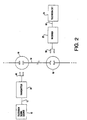
- a power line communications system constructed in accordance with the present invention, includes first signal conducting means, represented by a line 10, for supplying information signals over a first band of frequencies from an information signal source, such as a television signal source 12 by which cable television signals are delivered to a building.
- first signal conducting means represented by a line 10
- an information signal source such as a television signal source 12 by which cable television signals are delivered to a building.
- This power line communications system also includes a power line 14 and a plurality of outlets 16 and 18 individually connected to power line 10.
- the information signals are transmitted along the power from outlet 16 and are received at outlet 18 .
- These outlets may be connected directly by power line wires or may have circuit breakers or fuses in their path and may be on different phases of the power line.
- the reception and processing of television signals from a cable television connection box or a VCR requires selecting between channel 3 or channel 4 depending upon which of the two is not an active channel for the particular location.
- the information signals supplied from cable television connection box 18 are, ideally, over a band from 60 Mhz to 66 Mhz.
- the information signals supplied from cable television connection box 18 are, ideally, over a band from 66 Mhz to 72 Mhz.
- the Figure 2 power line communications system also includes a transmitter unit 20 and a receiver unit 22.
- Transmitter unit 20 receives the information signals and is adapted for connection to power line 14 to conduct the information signals to the power line.
- Receiver 22 also is adapted for connection to power line 14 and conducts the information signals to a utilization unit, such as a television set 24.
- transmitter unit 20 includes first local oscillator means 26 for supplying a first carrier signal and control means 28 for controlling first local oscillator means 26 to set the first carrier signal at a first predetermined frequency dependent upon the frequency band of a notch in the frequency response characteristic between a first of the outlets, namely outlet 16 to which transmitter unit 20 is intended to be connected, and a second of the outlets, namely outlet 18 to which receiver unit 22 is intended to be connected.
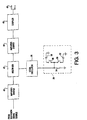
- Control means 28 can be in the form of a capacitor/switching network such as the one shown in Figure 3.
- a first switch 30 and a first capacitor 32 serve to select between channel 3 or channel 4 operation.
- the first carrier signal supplied by first local oscillator means 26 can be 83 Mhz.
- the first carrier signal supplied by first local oscillator means can be 89 Mhz.
- a second switch 36 and a third capacitor 38 serve to alleviate, as will be explained below, the effects of a notch in the frequency characteristic between outlet 16 to which transmitter unit 20 is adapted for connection and outlet 18 to which receiver unit 22 is adapted for connection.
- transmitter unit 20 includes first amplifier and shaper means 40 for amplifying and shaping the information signals supplied by television signal source 12 .
- Signals outside the range of frequencies of the information signals e.g. 60 Mhz to 72 Mhz for television signals are attenuated by amplifier and shaper means 40 .
- Transmitter unit 20 also includes first multiplier means 42 for frequency multiplying the first carrier signal supplied by first local oscillator means 26 and the information signals (e.g. either in the channel 3 band or the channel 4 band for television signals) to frequency shift the information signals to a second band of frequencies selected for power line transmission.
- first multiplier means 42 for frequency multiplying the first carrier signal supplied by first local oscillator means 26 and the information signals (e.g. either in the channel 3 band or the channel 4 band for television signals) to frequency shift the information signals to a second band of frequencies selected for power line transmission. This is shown in Figure 1 by the 6 Mhz band of the information signals extending between, for example, 17 Mhz and 23 Mhz. The amount of frequency shifting of the information signals is selected so that the frequencies of the information signals are below the 40 Mhz upper limit of operation of power line communication systems set by the government.
- picture information portion P of the television signal extending over a band of approximately 500 KHZ, falls at a NOTCH in the FREQUENCY RESPONSE CHARACTERISTIC which extends below an acceptable level illustrated by the dotted line.
- Those portions of the television signal, specifically the picture information portion P, falling within the band defined by where the dotted line crosses the FREQUENCY RESPONSE CHARACTERISTIC are likely to be lost due to severe attenuation.
- switch 36 in Figure 3 is closed and capacitor 38 is placed in parallel with capacitor 34 .
- Curve L-L corresponds to the "low" product of multiplication by first multiplier means 42 and extends between approximately 16.70 Mhz and approximately 22.70 Mhz with P L , corresponding to the picture information portion P of the television signal, above where the dotted line crosses the FREQUENCY RESPONSE CHARACTERISTIC.
- Curve H-H corresponds to the "high" product of multiplication by first multiplier means 42 and extends between approximately 17.20 Mhz and approximately 23.20 Mhz with P H , corresponding to the picture information portion P of the television signal, above where the dotted line crosses the FREQUENCY RESPONSE CHARACTERISTIC.
- One or the other of the products of the multiplication by multiplier means 42 can be used for the particular power line communications system.
- transmitter unit 20 includes second amplifier and shaper means 44 for amplifying and shaping the information signals after frequency shifting of the information signals by first multiplier means 42 and first coupler means 46 which provide filtering, isolation and impedance matching.
- Transmitter unit 20 also includes second signal conducting means, in the form of a plug 48 , for conducting to outlet 16 the information signals coupled to plug 48 after frequency shifting by first multiplier means 42 and amplifying and shaping of the information signals by first amplifier and shaper means 44.
- the information signals conducted to outlet 16 are transmitted along power line 14 to outlet 18.
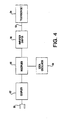
- receiver unit 22 includes third signal conducting means, in the form of a plug 50 , for conducting the information signals from outlet 18 .
- receiver unit 22 includes second coupler means 52 which provide isolation, impedance matching, and filtering.
- Receiver unit 22 also includes second local oscillator means 54 for supplying a second carrier signal having a second predetermined frequency and second multiplier means 56 for frequency multiplying the second carrier signal and the information signals conducted by plug 50 to frequency shift the information signals conducted by plug 50 to a band of frequencies at least approximately the same as the first band of frequencies.
- the utilization unit e.g. a television set
- the utilization unit arranged to receive information signals over a specific band of frequencies (e.g. 60 Mhz to 66 Mhz for channel 3 or 66 Mhz to 72 Mhz for channel 4)
- the information signals must be returned, from the frequency band over which the information signals are transmitted and received by the power line communications system, to at least approximately the frequency band at which they can be used by the utilization equipment.
- Second local oscillator means 54 is arranged to provide a second carrier signal having the requisite frequency such that, when the second carrier signal is multiplied with the information signals by second multiplier means 56 , the information signals are frequency shifted to the requisite band of frequencies.
- second local oscillator means 54 is set to supply either one of two carrier signals corresponding to either channel 3 operation or channel 4 operation.
- the second band of frequencies of the output of second multiplier means 56 will be only approximately the same as the first band of frequencies of the information signals supplied to transmitter unit 20.
- television set 24 can accommodate television signals having portions outside the prescribed 6 Mhz band for a particular channel.
- receiver unit 22 includes second amplifier and shaper means 58 for amplifying and shaping the information signals after frequency shifting of the information signals by second multiplier means 56.
- Receiver unit 22 also includes fourth signal conducting means, represented by a line 60, for conducting to a utilization unit the information signals after frequency shifting by second multiplier means 56 and amplifying and shaping of the information signals by third amplifier and shaper means 58 .
- fourth signal conducting means represented by a line 60, for conducting to a utilization unit the information signals after frequency shifting by second multiplier means 56 and amplifying and shaping of the information signals by third amplifier and shaper means 58 .
- transmitter unit 20 The components of transmitter unit 20 , namely first local oscillator means 26 , control means 28 , first amplifier and shaper means 40 , first multiplier means 42 , second amplifier and shaper means 44 , and first coupler means 46 can be arranged in a housing 62, such as the one shown in Figure 5.
- Plug 48 by which transmitter unit 22 is connected to outlet 16, and connector 10, by which information signals from an information signal source are supplied to the transmitter unit, are fixed to and extend from housing 62 .
- the components of receiver unit 22 can be arranged in a similar housing with plug 50 and connector 60 fixed to and extending from the housing.
- the present invention has application for communication of information signals other than television.
- a power line communications system constructed in accordance with the present invention, can be used to transmit and receive telephone signals.
- the entire audio signal can get lost in a notch because the audio frequency band is relatively narrow.
- both the location at which the telephone signal enters the power line and the location of an extension have a transmitter/receiver unit which is a combination of the transmitter unit of Figure 3 and the receiver unit of Figure 4. If the notch switch in the transmitter/receiver unit at the location at which the telephone signal enters the building is closed, the notch switch in the transmitter/receiver unit at the location of an extension also must be closed.
- Typical carrier frequencies for the local oscillators are 5.5 Mhz and 6.5 Mhz, one for each direction of transmission.
Landscapes
- Engineering & Computer Science (AREA)
- Power Engineering (AREA)
- Computer Networks & Wireless Communication (AREA)
- Signal Processing (AREA)
- Cable Transmission Systems, Equalization Of Radio And Reduction Of Echo (AREA)
Claims (9)
- Ein Netzleitungskommunikationssystem aufweisend:wobei die Sendeeinheit (20) weiterhin aufweisterste Signalleitungsmittel (10) zum Bereitstellen von Informationssignalen über ein erstes Frequenzband von einer Informationssignalquelle (12);eine Netzleitung (14);eine Mehrzahl von Steckdosen, welche individuell an die Netzleitung (14) angeschlossen sind, umfassend eine erste Steckdose (16), an der die Informationssignale gesendet werden und eine zweite Steckdose (18) an der die Informationssignale empfangen werden;eine Sendeeinheit (20) welche mit der ersten Steckdose (16) verbunden ist und umfasst:(a) erste Oszillatormittel (26) zum Bereitstellen eines ersten Trägersignals;(b) Steuermittel (28) zum Steuern der Oszillatormittel (26) um das erste Trägersignal auf eine erste vorbestimmte Frequenz einzustellen, in Abhängigkeit des Frequenzbandes einer Kerbe in der Frequenzantwortcharakteristik zwischen der ersten und der zweiten Steckdose (16, 18);(c) erste Multiplikatormittel (42) zum Multiplizieren der Frequenz des ersten Trägersignals und des Informationssignals, um das Informationssignal auf ein zweites Frequenzband frequenzzuverschieben; und(d) zweite Signalleitungsmittel (48) zum Leiten der Informationssignale nach der Frequenzverschiebung durch die ersten Multiplikatormittel (42) zu der ersten Steckdose 16 zum Senden der Informationssignale über die Netzleitung (14) zu der zweiten Steckdose (18); undeine Empfängereinheit (22), welche mit der zweiten Steckdose (18) verbunden ist, und umfasst:(a) dritte Signalleitungsmittel (50), zum Leiten der Informationssignale von der zweiten Steckdose (18);(b) zweite Oszillatormittel (54), zum Bereitstellen eines zweiten Trägersignals, welches eine zweite vorbestimmte Frequenz aufweist;(c) zweite Multiplikatormittel (56), zum Multiplizieren der Frequenz des zweiten Trägersignals und der Informationssignale, die durch die zweiten Leitungsmittel (48) geleitet werden, um die Informationssignale, die durch die zweiten Signalleitungsmittel geleitet werden auf ein Frequenzband frequenzzuverschieben, welches zumindest näherungsweise das gleiche ist, wie das erste Frequenzband; und(d) vierte Signalleitungsmittel (60) zum Leiten der Informationssignale nach der Frequenzverschiebung durch die zweiten Multiplikatormittel (56) an eine Verwendungseinheit (24);wobei die Empfängereinheit (22) weiterhin umfasst:(a) erste Verstärker und Formmittel (40) zum Verstärken und Formen der Informationssignale, welche durch die ersten Signalleitungsmittel (10) von der Informationssignalsquelle (12) bereitgestellt wurden;(b) zweite Verstärker und Formmittel (44), zum Verstärken und Formen der Informationssignale nach der Frequenzverschiebung der Informationssignale durch die ersten Multiplikatormittel (42); und(c) erste Kopplermittel (46), zum Koppeln der Informationssignale an die zweiten Signalleitungsmittel (48) nach der Frequenzverschiebung der Informationssignale durch die ersten Multiplikatormittel (42) und Verstärken und Formen der Informationssignale durch die zweiten Verstärker- und Formmittel (44); unddadurch gekennzeichnet, dass(a) zweite Kopplermittel (52) zum Koppeln der Informationssignale, die von den zweiten Leitungsmitteln (50) an die zweiten Multiplikatormittel (56) geleitet werden; und(b) dritte Verstärker- und Formmittel (58) zum Verstärken und Formen der Informationssignale nach der Frequenzverschiebung der Informationssignale durch die zweiten Multiplikatormittel (56);
die Steuermittel (28) einen Schalter (30) aufweisen, um die ersten Oszillatormittel (26) zu steuern, um selektiv das erste Trägersignal auf die erste vorbestimmte Frequenz einzustellen, wenn die Frequenzantwortcharakteristik zwischen der ersten Steckdose (16) und der zweiten Steckdose (18) eine Kerbe aufweist. - Ein Netzleitungskommunikationssystem gemäß Anspruch 1, wobei die Informationssignale Fernsehsignale sind, und die Verwendungseinheit ein Femsehgerät (24) ist.
- Ein Netzleitungskommunikationssystem gemäß Anspruch 2, wobei die Steuermittel (28) die ersten Oszillatormittel (26) steuern, um selektiv das erste Trägersignal auf die erste vorbestimmte Frequenz einzustellen, in Abhängigkeit des Kanal 3 oder Kanal 4 Betriebs des Fernsehgeräts (24).
- Ein Netzleitungskommunikationssystem gemäß Anspruch 2, wobei das Steuermittel (28) aufweist:(1) Einen ersten Schalter (30) zum Steuern der ersten Oszillatormittel (26) um selektiv das erste Trägersignal auf die erste vorbestimmte Frequenz einzustellen, in Abhängigkeit von einem Kanal 3 oder Kanal 4 Betrieb des Fernsehgeräts (24); und(2) ein zweiter Schalter (36) zum Steuern des ersten Oszillatormittels (26), um selektiv das erste Trägersignal auf die erste vorbestimmte Frequenz einzustellen, wenn die Frequenzantwortcharakteristik zwischen der ersten Steckdose (16) und der zweiten Steckdose (18) eine Kerbe aufweist.
- Eine Sendeeinheit für ein Netzleitungskommunikationssystem aufweisend:dadurch gekennzeichnet, dassSignalleitungsmittel (10) zum Bereitstellen von Informationssignalen über ein erstes Frequenzband von einer Informationssignalquelle (12);Lokale Oszillatormittel (26) zum Bereitstellen eines Trägersignals;Steuermittel (28) zum Steuern der lokalen Oszillatormittel, um das Trägersignal auf eine vorbestimmte Frequenz einzustellen, in Abhängigkeit des Frequenzbandes einer Kerbe in der Frequenzantwortcharakteristik zwischen einer ersten Steckdose (16) in dem Netzleitungskommunikationssystem, an die eine Sendeeinheit (20) angeschlossen werden kann, und einer zweiten Steckdose (18) in dem Netzleitungskommunikationssystem, an die eine Sendeeinheit(20) angeschlossen werden kann;Multiplikatorrnittel (42) zum Multiplizieren der Frequenz des Trägersignals und der Informationssignale, um die Informationssignale auf ein zweites Frequenzband frequenzzuverschieben;Signalleitungsmittel (48), zum Leiten der Informationssignale nach der Frequenzverschiebung durch die Multiplikatormittel (42) zu der ersten Steckdose (16) in dem Netzleitungskommunikationssystem, zum Senden der Informationssignale über eine Netzleitung (14) in dem Netzleitungskommunikationssystem zu einer zweiten Steckdose (18) in dem Netzleitungskommunikationssystem;(1) Erste Verstärker- und Formmittel (40) zum Verstärken und Formen der Informationssignale, welche durch die Signalleitungsmittel (10) von der Informationssignalquelle (12) bereit gestellt werden;(2) zweite Verstärker- und Formmittel (44) zum Verstärken und Formen der Informationssignale nach der Frequenzverschiebung der Informationssignale durch die Multiplikatormittel (42); und(3) Kopplermittel (46), zum Koppeln der Informationssignale zu dem Signalleitungsmittel (48), welches leitet, durch das die Informationssignale zu der ersten Steckdose (16) in dem Netzleitungskommunikationssystem geleitet werden, nach der Frequenzverschiebung der Informationssignale durch die Multiplikatormittel (42) und Verstärken und Formen der Informationssignale durch die Verstärker und Formmittel (44),
das Steuermittel (28) einen Schalter (30) aufweist, um die lokalen Oszillatormittel (26) zu steuern, um selektiv das Trägersignal auf die vorbestimmte Frequenz einzustellen, wenn die Frequenzantwortcharakteristik eine Kerbe zwischen der ersten Steckdose (16) in dem Netzleitungskommunikationssystem, an die die Sendeeinheit (20) angeschlossen werden kann, und der zweiten Steckdose (18) in dem Netzleitungskommunikationssystem, an die eine Sendeeinheit (20) angeschlossen werden kann, um mit der ersten Steckdose (16) verbunden zu sein, aufweist. - Eine Sendeeinheit für ein Netzleitungskommunikationssystem gemäß Anspruch 5, wobei die Informationssignale Fernsehsignale sind.
- Eine Sendeeinheit für ein Netzleitungskommunikationssystem gemäß Anspruch 6, wobei die Steuermittel (28) die lokalen Oszillatormittel (26) steuern, um selektiv das Trägersignal auf eine vorbestimmte Frequenz einzustellen, in Abhängigkeit eines Kanal 3 oder Kanal 4 Betriebes.
- Eine Sendereinheit für ein Netzleitungskommunikationssystem gem. Anspruch 6, wobei das Steuermittel (28) umfasst:(1) Einen ersten Schalter (30) zum Steuern der lokalen Oszillatormittel (26), um selektiv das Trägersignal auf die vorbestimmte Frequenz einzustellen, in Abhängigkeit eines Kanal 3 oder Kanal 4 Betriebs; und(2) ein zweiter Schalter (36) zum Steuern der lokalen Oszillatormittel (26), um selektiv das Trägersignal auf die vorbestimmte Frequenz einzustellen, wenn die Frequenzantwortcharakteristik eine Kerbe zwischen der ersten Steckdose (16) in dem Netzleitungskommunikationssystem, an die die Sendeeinheit (20) angeschlossen werden kann, und der zweiten Steckdose (18) in dem Netzleitungskommunikationssystem, an die eine Sendereinheit (20) angeschlossen werden kann, um mit der ersten Steckdose (16) verbunden zu sein, aufweist.
- Ein Verfahren zum Eliminieren des Effekts einer Kerbe in der Frequenzantwortcharakteristik zwischen ersten und zweiten Steckdosen (16, 18) in einem Netzleitungskommunikationssystem aufweisend die Schritte:wobei:Bereitstellen von Infarmationssignalen über ein erstes Frequenzband von einer Informationssignalquelle (12);Bereitstellen eines ersten Trägersignals;Steuern der Frequenz des ersten Trägersignals, um die Frequenz des ersten Trägersignals auf eine erste vorbestimmte Frequenz einzustellen, in Abhängigkeit eines Frequenzbandes einer Kerbe in einer Frequenzantwortcharakteristik zwischen ersten und zweiten Steckdosen (16, 18), die an eine Netzleitung (14) angeschlossen sind;Multiplizieren der Informationssignale mit dem ersten Trägersignal, nachdem die Frequenz des ersten Trägersignals eingestellt wurde, um die Frequenz des Informationssignals auf ein zweites Frequenzband zu verschieben, welches von dem Frequenzband der Kerbe in der Frequenzantwortcharakteristik zwischen den ersten und zweiten Steckdosen (16, 18), die an eine Netzleitung (14) angeschlossen sind, beabstandet istLeiten der Informationssignale nachdem die Frequenz der Informationssignale verschoben wurde, zu der ersten Steckdose (16) zum Senden der Informationssignale über eine Netzleitung (14) zu der zweiten Steckdose (18);Leiten der Informationssignale von der zweiten Steckdose (18);Bereitstellen eines zweiten Trägersignals, welches eine zweite vorbestimmte Frequenz aufweist;Multiplizieren des Informationssignals, das von der zweiten Steckdose (18) geleitet wurde, mit dem zweiten Trägersignal, um die Frequenz des Informationssignals, welches von der zweiten Steckdose (18) geleitet wird, auf ein Frequenzband zu verschieben, welches zumindest näherungsweise das gleiche ist wie das erste Frequenzband;Leiten der Informationssignale, welche von der zweiten Steckdose (18) geleitet werden, nachdem die Frequenz des Informationssignals, welches von der zweiten Steckdose (18) geleitet wird, verschoben wurde, zu einer Verwendungseinheit (24);(a) die Informationssignalquelle (12) eine Fernsehsignalquelle ist;(b) die Verwendungseinheit ein Fernsehgerät (24) ist; und(c) die Schritte des Steuems der Frequenz des ersten Trägersignals die folgendenden Schritte aufweisen:( 1 ) Steuern der Frequenz des ersten Trägersignals, um selektiv das erste Trägersignal auf die erste vorbestimmte Frequenz einzustellen, in Abhängigkeit eines Kanal 3 oder Kanal 5 Betriebes des Fernsehgeräts (24); und(2) Steuern der Frequenz des ersten Trägersignals, um selektiv das erste Trägersignal auf die erste vorbestimmte Frequenz einzustellen, in Abhängigkeit von der Frequenzantwortcharakteristik, die eine Kerbe aufweist, zwischen der ersten Steckdose (16) und der zweiten Steckdose (18).
Applications Claiming Priority (1)
| Application Number | Priority Date | Filing Date | Title |
|---|---|---|---|
| PCT/US1996/011062 WO1997050193A1 (en) | 1996-06-27 | 1996-06-27 | Power line communications system |
Publications (2)
| Publication Number | Publication Date |
|---|---|
| EP0965181A1 EP0965181A1 (de) | 1999-12-22 |
| EP0965181B1 true EP0965181B1 (de) | 2004-06-23 |
Family
ID=22255401
Family Applications (1)
| Application Number | Title | Priority Date | Filing Date |
|---|---|---|---|
| EP96923526A Expired - Lifetime EP0965181B1 (de) | 1996-06-27 | 1996-06-27 | Netzleitungsübertragungssystem |
Country Status (5)
| Country | Link |
|---|---|
| EP (1) | EP0965181B1 (de) |
| AU (1) | AU6401496A (de) |
| DE (1) | DE69632793T2 (de) |
| ES (1) | ES2223065T3 (de) |
| WO (1) | WO1997050193A1 (de) |
Families Citing this family (12)
| Publication number | Priority date | Publication date | Assignee | Title |
|---|---|---|---|---|
| US6480510B1 (en) | 1998-07-28 | 2002-11-12 | Serconet Ltd. | Local area network of serial intelligent cells |
| US6690677B1 (en) | 1999-07-20 | 2004-02-10 | Serconet Ltd. | Network for telephony and data communication |
| US6549616B1 (en) | 2000-03-20 | 2003-04-15 | Serconet Ltd. | Telephone outlet for implementing a local area network over telephone lines and a local area network using such outlets |
| IL135744A (en) | 2000-04-18 | 2008-08-07 | Mosaid Technologies Inc | Telephone communication system over a single telephone line |
| IL144158A (en) | 2001-07-05 | 2011-06-30 | Mosaid Technologies Inc | Socket for connecting an analog telephone to a digital communications network that carries digital voice signals |
| IL161190A0 (en) | 2001-10-11 | 2004-08-31 | Serconet Ltd | Outlet with analog signal adapter, method for use thereof and a network using said outlet |
| IL152824A (en) | 2002-11-13 | 2012-05-31 | Mosaid Technologies Inc | A socket that can be connected to and the network that uses it |
| HK1060026A2 (en) * | 2003-01-18 | 2004-06-25 | Access Ip Limited | Power line communication system |
| IL157787A (en) | 2003-09-07 | 2010-12-30 | Mosaid Technologies Inc | Modular outlet for data communications network |
| IL159838A0 (en) | 2004-01-13 | 2004-06-20 | Yehuda Binder | Information device |
| IL160417A (en) | 2004-02-16 | 2011-04-28 | Mosaid Technologies Inc | Unit added to the outlet |
| US7873058B2 (en) | 2004-11-08 | 2011-01-18 | Mosaid Technologies Incorporated | Outlet with analog signal adapter, a method for use thereof and a network using said outlet |
Family Cites Families (2)
| Publication number | Priority date | Publication date | Assignee | Title |
|---|---|---|---|---|
| US4847903A (en) * | 1987-05-22 | 1989-07-11 | Recoton Corporation | Wireless remote speaker system |
| WO1992021194A1 (en) * | 1991-05-10 | 1992-11-26 | Echelon Corporation | Power line communication while avoiding determinable interference harmonics |
-
1996
- 1996-06-27 AU AU64014/96A patent/AU6401496A/en not_active Abandoned
- 1996-06-27 EP EP96923526A patent/EP0965181B1/de not_active Expired - Lifetime
- 1996-06-27 WO PCT/US1996/011062 patent/WO1997050193A1/en not_active Ceased
- 1996-06-27 DE DE69632793T patent/DE69632793T2/de not_active Expired - Fee Related
- 1996-06-27 ES ES96923526T patent/ES2223065T3/es not_active Expired - Lifetime
Also Published As
| Publication number | Publication date |
|---|---|
| ES2223065T3 (es) | 2005-02-16 |
| AU6401496A (en) | 1998-01-14 |
| WO1997050193A1 (en) | 1997-12-31 |
| DE69632793D1 (de) | 2004-07-29 |
| EP0965181A1 (de) | 1999-12-22 |
| DE69632793T2 (de) | 2005-07-14 |
Similar Documents
| Publication | Publication Date | Title |
|---|---|---|
| US5712614A (en) | Power line communications system | |
| US4912553A (en) | Wideband video system for single power line communications | |
| US6321384B1 (en) | Noise reduction in cable return paths | |
| US5705974A (en) | Power line communications system and coupling circuit for power line communications system | |
| US3886454A (en) | Control apparatus for a two-way cable television system | |
| US5066939A (en) | Method and means of operating a power line carrier communication system | |
| JP3256457B2 (ja) | 通信ネットワーク用の中央ノード変換装置及び方法 | |
| US5027426A (en) | Signal coupling device and system | |
| US6151480A (en) | System and method for distributing RF signals over power lines within a substantially closed environment | |
| US5485040A (en) | Powerline coupling network | |
| US8010061B2 (en) | Combining multimedia signaling and wireless network signaling on a common communication medium | |
| US20030006881A1 (en) | System and method for power line communication | |
| EP0965181B1 (de) | Netzleitungsübertragungssystem | |
| US20120025929A1 (en) | Filter with improved impedance match to a hybrid coupler | |
| US20150201239A1 (en) | Upstream bandwidth conditioning device | |
| CA2234024C (en) | System to reduce gain variance and ingress in catv return transmissions | |
| US4139735A (en) | Carrier current communications system | |
| US6006066A (en) | Transmission system with tap devices which reduce the effects of interference | |
| US3022504A (en) | Two-way radio telephone system utilizing frequency subbands to provide transmitter-receiver isolation | |
| US6600900B1 (en) | System and method providing bi-directional communication services between a service provider and a plurality of subscribers | |
| EP1675288B1 (de) | Anordnung zur übertragung eines datensignals in einem kabelfernsehnetzwerk | |
| EP0965178B1 (de) | System und ankoppelschaltung zur nachrichtenübertragung | |
| RU2101868C1 (ru) | Устройство для передачи информации | |
| KR100737555B1 (ko) | 이동통신 시스템의 적응 간섭 제어 장치 | |
| KR930003388Y1 (ko) | 전송선로 트랜스를 주축으로한 케이블 다중방송 송출 및 전송장치 |
Legal Events
| Date | Code | Title | Description |
|---|---|---|---|
| PUAI | Public reference made under article 153(3) epc to a published international application that has entered the european phase |
Free format text: ORIGINAL CODE: 0009012 |
|
| 17P | Request for examination filed |
Effective date: 19990423 |
|
| AK | Designated contracting states |
Kind code of ref document: A1 Designated state(s): DE ES FR GB IT |
|
| 17Q | First examination report despatched |
Effective date: 20020723 |
|
| GRAP | Despatch of communication of intention to grant a patent |
Free format text: ORIGINAL CODE: EPIDOSNIGR1 |
|
| GRAS | Grant fee paid |
Free format text: ORIGINAL CODE: EPIDOSNIGR3 |
|
| GRAA | (expected) grant |
Free format text: ORIGINAL CODE: 0009210 |
|
| AK | Designated contracting states |
Kind code of ref document: B1 Designated state(s): DE ES FR GB IT |
|
| REG | Reference to a national code |
Ref country code: GB Ref legal event code: FG4D |
|
| REF | Corresponds to: |
Ref document number: 69632793 Country of ref document: DE Date of ref document: 20040729 Kind code of ref document: P |
|
| REG | Reference to a national code |
Ref country code: ES Ref legal event code: FG2A Ref document number: 2223065 Country of ref document: ES Kind code of ref document: T3 |
|
| ET | Fr: translation filed | ||
| PLBE | No opposition filed within time limit |
Free format text: ORIGINAL CODE: 0009261 |
|
| STAA | Information on the status of an ep patent application or granted ep patent |
Free format text: STATUS: NO OPPOSITION FILED WITHIN TIME LIMIT |
|
| 26N | No opposition filed |
Effective date: 20050324 |
|
| PGFP | Annual fee paid to national office [announced via postgrant information from national office to epo] |
Ref country code: IT Payment date: 20060630 Year of fee payment: 11 |
|
| PGFP | Annual fee paid to national office [announced via postgrant information from national office to epo] |
Ref country code: ES Payment date: 20060713 Year of fee payment: 11 |
|
| PGFP | Annual fee paid to national office [announced via postgrant information from national office to epo] |
Ref country code: DE Payment date: 20070705 Year of fee payment: 12 |
|
| PGFP | Annual fee paid to national office [announced via postgrant information from national office to epo] |
Ref country code: GB Payment date: 20070627 Year of fee payment: 12 |
|
| PGFP | Annual fee paid to national office [announced via postgrant information from national office to epo] |
Ref country code: FR Payment date: 20070608 Year of fee payment: 12 |
|
| REG | Reference to a national code |
Ref country code: ES Ref legal event code: FD2A Effective date: 20070628 |
|
| PG25 | Lapsed in a contracting state [announced via postgrant information from national office to epo] |
Ref country code: ES Free format text: LAPSE BECAUSE OF NON-PAYMENT OF DUE FEES Effective date: 20070628 |
|
| GBPC | Gb: european patent ceased through non-payment of renewal fee |
Effective date: 20080627 |
|
| REG | Reference to a national code |
Ref country code: FR Ref legal event code: ST Effective date: 20090228 |
|
| PG25 | Lapsed in a contracting state [announced via postgrant information from national office to epo] |
Ref country code: DE Free format text: LAPSE BECAUSE OF NON-PAYMENT OF DUE FEES Effective date: 20090101 |
|
| PG25 | Lapsed in a contracting state [announced via postgrant information from national office to epo] |
Ref country code: GB Free format text: LAPSE BECAUSE OF NON-PAYMENT OF DUE FEES Effective date: 20080627 |
|
| PG25 | Lapsed in a contracting state [announced via postgrant information from national office to epo] |
Ref country code: FR Free format text: LAPSE BECAUSE OF NON-PAYMENT OF DUE FEES Effective date: 20080630 |
|
| PG25 | Lapsed in a contracting state [announced via postgrant information from national office to epo] |
Ref country code: IT Free format text: LAPSE BECAUSE OF NON-PAYMENT OF DUE FEES Effective date: 20070627 |